


Maximizing heat sink surface area by packing ultra-thin, tightly spaced fins often increases thermal resistance and drives CNC machining costs up by 300%. For a high-performance CNC machined heat sink, the optimal balance requires a heat sink fin thickness between 1.5 mm and 2.5 mm, an aspect ratio below 8:1, and a heat sink base thickness sized to a 45-degree conduction spreading angle. Factoring in machine tool access, cutter deflection, and bottom root radii early prevents boundary layer choking, tool chatter, and baseplate warping.
Why Over-Optimizing Fin Density Fails in CNC Production?
Thermal engineers frequently fall into the geometric surface area trap during early-stage heat sink design. In standard computational fluid dynamics (CFD) packages, setting fin thickness to 0.5 mm with a 1.0 mm pitch shows high convective heat transfer coefficients due to the massive active surface area. However, translating these digital models into a physical custom aluminum heat sink design on 3-axis or 5-axis CNC machining centers introduces severe physical constraints that simulation defaults ignore. Reviewing fundamental aluminum CNC machining cost factors early helps avoid designing unmanufacturable fin configurations.
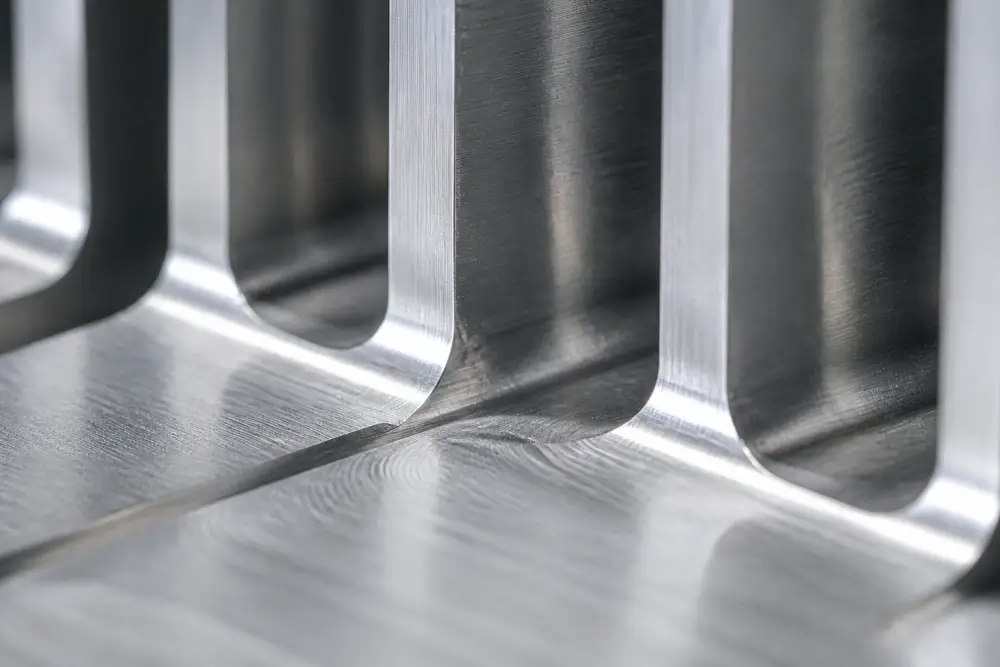
The Disconnect Between CFD Flow Simulations and Shop-Floor Tooling
At the machine spindle, high-aspect-ratio thin fins lack structural rigidity. When a solid carbide end mill engages an unsupported 0.8 mm aluminum wall at 12,000 RPM, the cutting forces trigger severe acoustic resonance and high-frequency tool chatter. This chatter leads to:
· Fin wall taper and dimensional drift exceeding ±0.2 mm.
· Heavy burr formation at the tip that requires manual secondary deburring.
· Micro-cracks along the fin root due to cyclic bending loads.
· Catastrophic tool breakage when small-diameter cutters clear deep, narrow channels.
Chatter, Blade Deflection, and the True Cost of Ultra-Thin Fins
From two decades of prototype-to-volume manufacturing at Dazao utilizing advanced CNC machining services, empirical production data shows that reducing fin count by 20% while increasing fin thickness and channel pitch often yields identical or superior cooling. Widening the channel lowers fluid pressure drop, prevents boundary-layer thermal choking, and allows rigid tooling to cut production cycle times by more than 50%. Robust heat sink design guidelines must treat thermal performance and CNC tool kinematics as an interconnected system.
Heat Sink Thermal Resistance Calculation and Physical Boundary Constraints
Establishing a manufacturable aluminum heat sink design begins by defining the thermal resistance budget before selecting fin geometry.
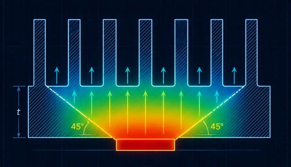
Establishing the Thermal Resistance Budget Chain
Thermal dissipation follows a continuous temperature drop along the conductive and convective path. A systematic heat sink thermal resistance calculation balances the power budget:
1. Identify total power dissipation in Watts.
2. Establish the operational temperature headroom by subtracting the maximum ambient air temperature from the maximum allowable silicon junction temperature.
3. Calculate the total allowable system thermal resistance by dividing the temperature headroom by the total power dissipation.
4. Subtract the component internal junction-to-case thermal resistance and the thermal interface material (TIM) contact resistance from the total allowable resistance.
The remaining value represents the target thermal resistance for the heat sink base and fin array. If the target thermal resistance is below 0.15 degrees Celsius per Watt in a compact footprint, passive natural convection becomes physically impossible, requiring forced convection or embedded phase-change hardware.
Fluid Dynamics: Natural Convection vs. Forced Airflow Boundaries
The flow regime dictates the physical boundaries of heat sink fin spacing:
· Natural Convection: Air movement relies solely on buoyancy forces generated by air density gradients. Fluid velocity rarely exceeds 0.2 to 0.5 m/s. If the fin spacing is smaller than 6.0 mm, thermal boundary layers merging from opposing fin walls choke the upward convective draft, creating a stagnant air blanket that elevates junction temperatures.
· Forced Convection: Static pressure delivered by axial fans or blowers drives air velocities between 1.5 m/s and 6.0 m/s through the fin channels. Thinner boundary layers allow tight fin pitches between 1.5 mm and 3.5 mm. However, if the hydraulic resistance of the fin array exceeds the fan static pressure curve, air takes the path of least resistance and bypasses the heat sink entirely. Designers should consult CNC wall thickness design rules to ensure fin structures withstand air pressure and mechanical clamping.
Base Thickness and the 45-Degree Thermal Spreading Angle
The heat sink base thickness serves as the primary thermal reservoir and lateral conduction plane. Point heat sources, such as power MOSFETs or high-density processing units, transfer heat downward and outward through the metal matrix at an effective 45-degree conduction angle.
When the base is too thin (for example, under 3.0 mm for a 30 mm x 30 mm heat source), localized thermal saturation occurs directly beneath the die. The outer regions of the fin array remain cold, resulting in poor thermal utilization. Conversely, an excessively thick base adds redundant component weight and complicates internal deep pocket milling strategies. As a reliable manufacturing rule of thumb, base thickness should equal at least 1.5 to 2.0 times the fin thickness, and never less than 50% of the distance from the heat source edge to the heat sink outer boundary.
Fin Geometry Parameters: CNC Machining Limits vs. Thermal Dissipation
Balancing heat sink fin height, thickness, and spacing determines both the production cost curve and the actual cooling output.
Fin Thickness Limits, Tool Vibration, and Feed Rates
For structural integrity during CNC slot milling, fin walls must withstand lateral cutting pressure:
· Below 1.0 mm: Aluminum fins behave like flexible cantilevers. High-speed end mills cause fin chatter, leading to rough wall finishes (Ra > 3.2 um), dimensional taper, and audible resonance during machining.
· 1.2 mm to 1.5 mm: The practical minimum for standard production. Requires specialized toolpaths, reduced depths of cut, and light radial engagement stepover, which increases machine cycle times.
· 1.5 mm to 3.0 mm: The optimal balance for machining economy. This thickness allows standard solid carbide tools to run at aggressive feeds and speeds on modern precision CNC milling capabilities without wall deflection, maintaining tight tolerances within ±0.05 mm.
Fin Spacing Constraints and Slitting Cutter Clearance
The clearance between fins dictates the maximum tool diameter a machine shop can utilize:
· If fin spacing is 2.0 mm, the machinist must employ an end mill with a maximum diameter of 1.5 mm to 1.8 mm to ensure proper chip evacuation and clearance.
· Long-reach micro-end mills have low cross-sectional rigidity. Cutter deflection increases with the cube of the unsupported tool length.
· When fin spacing drops below 1.5 mm, chip pack-up occurs inside the slot. Trapped aluminum chips fuse to the cutter flutes, causing immediate tool breakage and tearing fin surfaces.
Fin Height and the 8:1 Aspect Ratio Ceiling
The fin aspect ratio is defined as the total fin height divided by the individual fin thickness:
· Standard CNC Milling: Economical aspect ratios range from 3:1 to 6:1.
· Extended CNC Milling: Aspect ratios from 6:1 to 8:1 require multiple stepped-depth passes, customized extended-neck tooling, and reduced cutting feeds, increasing machining costs.
· Aspect Ratios Above 8:1: Not recommended for pure CNC machining due to severe tool deflection and fin vibration. Ratios from 10:1 to 25:1 require alternative fabrication processes such as skiving or extrusion.
|
Fin Aspect Ratio (H : T) |
Machining Difficulty |
Relative CNC Cost (%) |
Primary Risk Factors |
|
Up to 4:1 |
Low |
Baseline (100%) |
Minimal; standard end mills, high feed rates |
|
4:1 to 6:1 |
Moderate |
130% - 160% |
Minor tool deflection; requires stepped depth |
|
6:1 to 8:1 |
High |
200% - 300% |
Severe chatter, cutter breakage, wall taper |
|
Greater than 8:1 |
Extreme / Impractical |
> 450% |
Tool stall, chip welding; requires EDM or skiving |
The Root Corner Radius Trap: Bridging the CFD Simulation Gap
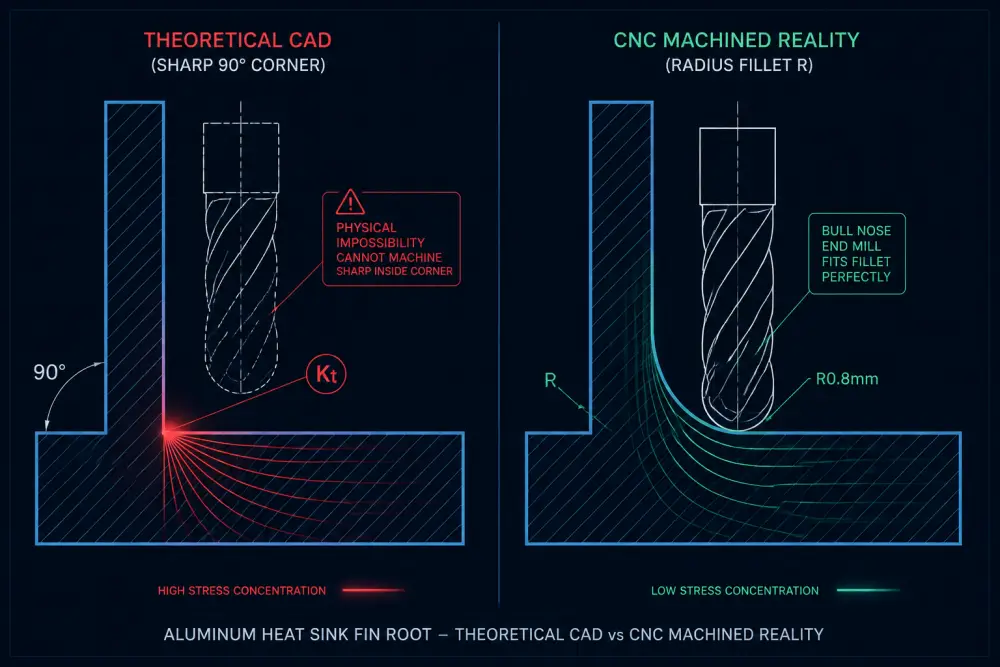
A common oversight in thermal modeling is omitting the internal bottom radius. Standard thermal simulations assume clean, 90-degree square corners at the intersection where the fin wall meets the baseplate floor.
In physical CNC production, end mills have corner radii to prevent cutting edge chipping. A flat-bottom end mill leaves a corner transition radius between R0.3 mm and R1.0 mm. Reviewing CNC corner radius cost optimization demonstrates why eliminating these fillets drives up tooling expense.
This root fillet accumulation causes two distinct physical effects:
1. Boundary-Layer Airflow Constriction: In forced convection systems with low fin channels, root fillets reduce the effective cross-sectional flow area at the highest-conduction zone by 4% to 8%, elevating channel air resistance and causing unpredicted static pressure drop.
2. Thermal Conduction Support: Positively, the root radius acts as a natural conductive gusset, lowering localized thermal resistance at the fin base joint and improving structural stiffness against vibration.
Engineering drawings must explicitly specify a root corner radius of R0.5 mm or greater rather than sharp internal corners.
Baseplate Flatness, Residual Stress Relief, and Thermal Interface Resistance
Achieving minimum thermal resistance across the component interface requires direct physical contact between the semiconductor package and the heat sink base. Surface irregularities, angular tilt, and baseplate warpage introduce micro-scale air voids. Because stagnant air has an extremely low thermal conductivity of roughly 0.026 W/mK, uncontrolled surface topology degrades heat transfer before thermal energy ever reaches the fin array.
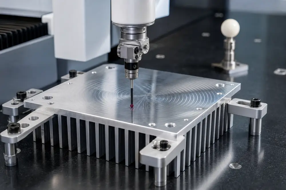
Surface Roughness vs. True Flatness: The TIM Gap Reality
Engineering drawings often confuse surface roughness with surface flatness:
· Surface Roughness (Ra): Defines microscopic peak-to-valley tool marks. An as-machined finish of Ra 0.8 um to Ra 1.6 um provides an optimal mechanical substrate for thermal grease, phase-change pads, or gap fillers. Specifying a mirror-polished Ra 0.2 um surface adds significant fly-cutting or lapping cost without measurable thermal benefits, because thermal interface materials (TIM) are engineered specifically to wet and fill microscopic tool tracks.
· Surface Flatness: Defines macroscopic deviation across the entire mounting span. A flatness tolerance of 0.05 mm over a 100 mm reference length is standard for high-power electronics per aluminum CNC machining tolerance standards. If flatness exceeds 0.10 mm, rigid semiconductor packages cannot deform to bridge the gap, leading to uneven TIM thickness, localized dryout, and catastrophic junction over-temperature failures.
Residual Stress Release: Preventing Baseplate Bowing After Heavy CNC Hogging
A critical failure mode in precision manufacturing occurs when removing large material volumes from solid aluminum billets. Standard Al6061-T6 plate contains internal residual stresses resulting from rapid water quenching and mechanical stretching during raw material production. When CNC machine tools hog out 60% to 75% of the total block volume to create deep channels, the metallurgical stress balance is destroyed.
When unclamped from the machine vise, the baseplate relieves internal tension by bowing upward or downward by 0.10 mm to 0.25 mm:
· A convex bow focuses mechanical pressure entirely on the center of the silicon die, risking package cracking while lifting the outer fin zones.
· A concave bow creates a thick, fluid-starved pocket directly over the primary heat source where the TIM layer exceeds its maximum thermal design thickness.
The Dazao Machining Protocol for Flatness Verification
To guarantee a certified base flatness of 0.02 mm to 0.05 mm on thin-base, tall-fin designs, Dazao implements a multi-stage stress-relief machining protocol based on strict engineering guidelines for aluminum CNC machining:
1. Rough Milling: High-efficiency trochoidal milling paths remove 85% of the slot volume, leaving 0.5 mm of finishing stock on all surfaces.
2. Thermal Stress Relief: Semi-machined components undergo a controlled furnace bake at 180 to 200 degrees Celsius for two hours, followed by slow furnace cooling to eliminate induced mechanical tension.
3. Custom Vacuum Fixturing: For final skim passes, parts are secured using porous vacuum chucks rather than high-pressure mechanical edge clamps that introduce elastic deformation during cutting.
4. Balanced High-Speed Fly Cutting: Diamond-insert face mills take light skim cuts (0.05 mm depth of cut) at 10,000 RPM, producing a stable, stress-free mounting base with verified flatness.
Surface Treatments: Thermal Emissivity, Dielectric Insulation, and Chemical Trapping
Surface conversion coatings protect aluminum against atmospheric oxidation and modify thermal radiation properties. However, selecting surface treatments without accounting for coating chemistry can introduce thermal and assembly failures. For a detailed breakdown of chemical coatings, refer to our aluminum surface finishing and anodizing guide.
Radiative Heat Transfer: When Black Anodizing Actually Matters
Untreated, bare milled aluminum has a low thermal emissivity rating between 0.04 and 0.06, meaning it reflects more than 94% of radiant thermal energy back into the part. Applying an industry-standard Type II black or clear sulfuric acid anodized coating (10 to 15 um thickness) builds an open-pore aluminum oxide film that elevates surface emissivity to 0.82 through 0.88.
The practical impact depends on the cooling mode:
· Natural Convection Enclosures: Radiation accounts for 20% to 35% of total heat dissipation. Anodizing is mandatory; omitting it can raise steady-state component temperatures by 8 to 15 degrees Celsius.
· Forced Air Systems (Air Velocity > 2.5 m/s): Forced convective heat transfer completely dominates the energy balance. Radiation accounts for less than 3% of net dissipation. Under high-speed airflow, unanodized, clear-chromated, or electroless nickel-plated heat sinks perform almost identically to black anodized variants.
Hard Anodizing (Type III) as a Thermal Insulating Barrier
While standard Type II anodizing provides minimal conductive thermal resistance due to its thin layer, specifying Type III Hard Anodizing (Mil-A-8625, 35 to 50 um thickness) creates an operational penalty. Hard anodized coatings consist of dense, non-conductive aluminum oxide ceramics with an intrinsic thermal conductivity of only 1.0 to 1.5 W/mK, compared to 167 W/mK for the underlying Al6061-T6 alloy substrate. A 50 um hardcoat layer on the primary mounting pad introduces a measurable conduction thermal barrier, increasing junction temperatures under high heat fluxes.
Chemical Trapping and Salt Blooming in High-Aspect-Ratio Channels
When an engineering drawing features tight fin spacing (under 2.0 mm) combined with tall fins (aspect ratios over 5:1), surface tension prevents standard dip-tank rinses from circulating freely through the bottom channels.
If sulfuric acid from the anodizing bath remains trapped inside the slot roots:
· The acidic residue slowly evaporates during warehouse storage or field operation.
· Trapped chemicals react with moisture to form powdery white aluminum sulfate crystals (salt blooms) along the fin roots.
· These salt blooms bridge the fin gap, corrode the protective finish, and shed conductive particulate onto nearby printed circuit boards.
To prevent salt blooming, Dazao enforces a three-stage ultrasonic neutralization cycle combined with pressurized heated de-ionized water flushes for all narrow-channel custom orders.
|
Surface Treatment Type |
Emissivity (0 to 1) |
Thermal Barrier Risk |
Optimal Application Scenario |
|
Bare / Degreased As-Milled |
0.04 - 0.06 |
None |
Temporary test benches, non-corrosive lab use |
|
Type II Sulfuric Anodize |
0.82 - 0.88 |
Very Low (< 15 um) |
Natural convection, outdoor enclosures, LED |
|
Type III Hard Anodize |
0.85 - 0.90 |
Moderate (35 - 50 um) |
Extreme abrasive / marine environments only |
|
Chemical Film (Chromate) |
0.08 - 0.12 |
Zero (negligible film) |
Grounding required, high-speed forced air |
|
Electroless Nickel Plating |
0.05 - 0.10 |
Low |
Soldered thermal assemblies, copper bonding |
Engineering Callouts for Selective Contact Surface Masking
If high-voltage electrical isolation is not required, component mounting pads should be masked during Type III hard anodizing, or locally spot-faced via a light secondary CNC fly-cut after anodization. Specify selective masking on production drawings using explicit callouts: Surface area within designated boundary to remain free of anodic coating; chemical conversion coating per MIL-DTL-5541 permitted for corrosion protection.
Material Selection Tradeoffs: AL6061, AL6063, and Pure Copper C1100
Material choice governs thermal conduction rates, raw stock pricing, cutting tool life, and allowable structural complexity. Integrating thermal features directly into mechanical housings requires consulting a custom aluminum CNC machining design guide.
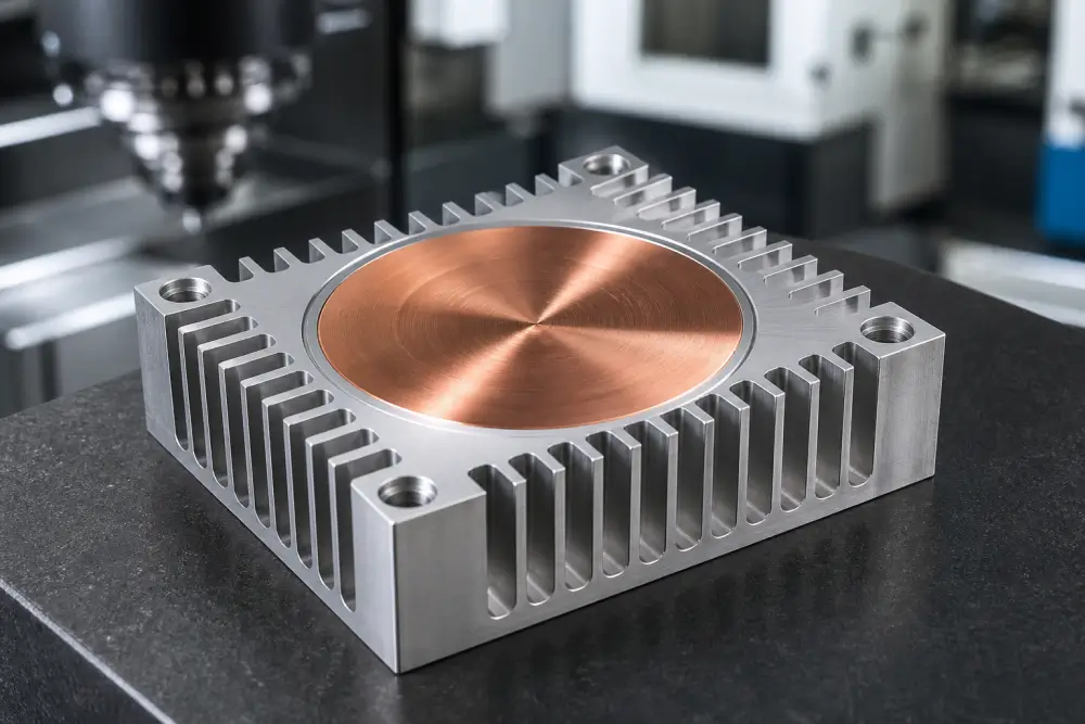
AL6061-T6 vs. AL6063-T6: Structural Rigidity vs. Gummy Tool Wear
· AL6061-T6: The benchmark alloy for precision machining. It provides a thermal conductivity of approximately 167 W/mK. High silicon and magnesium content produces short, brittle chips that evacuate rapidly from deep slots. It retains a high yield strength of 276 MPa, allowing robust structural threads per blind and threaded CNC hole design standards.
· AL6063-T6: The dominant alloy for extruded profiles due to its higher thermal conductivity (approximately 201 W/mK). However, choosing AL6063 for pure CNC machining introduces severe manufacturing trade-offs. The alloy is soft and ductile under cutting loads, causing long chips to weld to tool flutes and creating heavy burrs along fin tips that increase deburring labor costs by 25% to 40%.
Pure Copper C1100: Maximum Conduction at High Weight and Tooling Cost
Oxygen-free copper (C1100 / C10100) provides a thermal conductivity of roughly 390 W/mK, more than double that of Al6061. It is the preferred material for high-heat-flux hot spots exceeding 50 W/cm2.
However, pure copper introduces severe mechanical penalties:
· Mass Density: Copper weighs 8.96 g/cm3 , compared to 2.70 g/cm3 for aluminum. A solid copper cooler adds over 330% more weight to the PCB mounting assembly, often requiring structural backplates to prevent board flexing under shock and vibration.
· Machining Difficulty: Copper is extremely ductile and strain-hardens rapidly. Tool wear rates are three to five times higher than in aluminum. Machining deep, thin fins in copper requires aggressive flood coolant, specialized polished diamond tooling, and conservative cutting speeds, increasing machine cycle costs substantially.
Hybrid Copper-Inlay Baseplate Engineering
Rather than milling an entire heat sink from solid copper billet, the industry-standard approach uses a hybrid architecture:
1. Machine the primary baseplate and fin array from lightweight, cost-effective Al6061-T6.
2. CNC mill a precision pocket in the baseplate directly under the high-power silicon die.
3. Interference press-fit or solder a precision-ground C1100 copper spreader slug or vapor chamber into the pocket.
This hybrid configuration delivers 90% of the thermal performance of a solid copper heat sink while cutting overall component mass by 60% and reducing machining costs by half.
|
Material Grade |
Thermal Conductivity (W/mK) |
Density ( g/cm3 ) |
Machinability Index |
Typical Application |
|
Al6061-T6 |
167 - 170 |
2.70 |
100% (Baseline) |
Enclosure-integrated CNC parts |
|
Al6063-T6 |
200 - 205 |
2.69 |
65% (Gummy, burrs) |
Extruded profiles only |
|
Pure Copper (C1100) |
385 - 395 |
8.96 |
30% (High tool wear) |
Extreme heat flux dies |
|
Al6061 + Cu Inlay |
~ 280 (Effective spread) |
~ 3.80 |
85% (High efficiency) |
High-performance servers |
Manufacturing Decision Tree: CNC Machined Heat Sink vs. Extrusion vs. Skiving
Selecting the right production process depends on production volumes, dimensional complexity, fin density, and initial tooling budgets. Evaluating CNC heat sink vs extrusion dynamics early protects hardware development schedules.
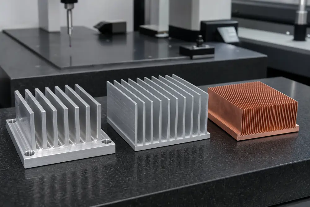
Comparative Analysis: Tooling Cost, Tolerance, and Aspect Ratios
· Aluminum Extrusion: Molten billet is forced through a hardened steel die. Tooling costs are low ($1,500 to $4,000), and unit costs are minimal at volume. However, fin geometry is strictly linear and uniform along the extrusion axis. Secondary CNC machining is still required to add mounting holes, pockets, and cutouts.
· Skived Fin Technology: A curved knife slices and folds thin shavings from a solid metal block to form integral, high-density fins. Skiving achieves aspect ratios over 25:1 with zero interface resistance. However, skived fins are fragile, cannot tolerate side-load forces, and cannot produce integrated perimeter mounting walls or complex 3D features.
· 5-Axis CNC Machining: Raw billet is shaped on multi-axis machining centers. While unit cycle time is higher, CNC offers complete design freedom: complex multi-directional pin arrays, integrated o-ring sealing grooves, multi-level stepped baseplates, and threaded blind features on any surface.
|
Parameter |
CNC Milling |
Aluminum Extrusion |
Skived Fin |
|
Fin Thickness Min. |
1.0 mm - 1.2 mm |
1.0 mm - 1.2 mm |
0.2 mm - 0.5 mm |
|
Fin Spacing Min. |
1.5 mm |
2.0 mm |
0.5 mm |
|
Max Aspect Ratio |
6:1 (Standard) / 8:1 |
10:1 (Standard) / 16:1 |
Up to 25:1 - 30:1 |
|
3D Geometry Freedom |
Complete (Any angle) |
Linear cross-section |
Linear array only |
|
Initial Tooling Cost |
$0 (NRE only) |
$1,500 - $5,000 (Die) |
Minimal ($0 - $1,000) |
|
Best Production Volume |
1 to 2,500 units |
2,500 to 100,000+ |
500 to 10,000 units |
The NPI Danger: The Prototype CNC to Mass Extrusion Aspect Ratio Inversion
The most common failure in hardware new product introduction (NPI) occurs during the transition from prototype to mass production:
A design team prototypes a heat sink on a 5-axis CNC machining center. Because CNC can cut complex geometries, the engineer specifies a customized array featuring 1.0 mm thick fins, 1.8 mm spacing, and a 45 mm fin height (a 45:1 aspect ratio relative to spacing), along with staggered pin cuts for omnidirectional flow.
The prototype performs well thermally. However, when transitioning to volume manufacturing (50,000 units/year), the team attempts to convert the design directly to standard aluminum extrusion to reduce piece-part costs.
Extrusion suppliers reject the print immediately. Standard commercial extrusion dies have a maximum die tongue aspect ratio limit of roughly 10:1 to 14:1. Forcing a die to extrude tall, closely spaced fins causes the steel die tongues to bend or snap under high billet extrusion pressures. The engineering team is forced to redesign the fin array, reducing fin height, widening fin spacing, and opening up the entire thermal enclosure. This introduces major project delays and requires re-testing and regulatory re-certification.
Production Volume Break-Even Matrix
To ensure continuous design continuity from initial validation through high-volume production:
· Prototypes (1 to 50 units): CNC machine directly from solid Al6061-T6 billet. Ensure fin parameters stay within standard extrusion limits (aspect ratio < 10:1) so geometry can transfer smoothly to production dies later.
· Low-to-Mid Volume (50 to 2,500 units/year): Maintain fully CNC machined construction through a dedicated CNC aluminum heat sink milling service. The upfront capital expense, lead time (6 to 8 weeks), and minimum order quantities (MOQs) of extrusion dies and skiving setups outweigh CNC unit costs.
· High Volume (2,500+ units/year): Invest in custom extrusion tooling to form the baseplate and primary fin array, then route parts through secondary CNC machining cells at Dazao to add precision-machined mounting faces, seal grooves, and threaded holes.
Engineering and Procurement DFM Checklist: Pre-RFQ Verification
Before submitting CAD files and 2D drawings to Dazao or other manufacturing partners, verify your design against this production-ready CNC DFM checklist to prevent engineering change orders (ECOs) and quote delays.
Geometric and Cutter Clearance Rules
· Does the fin spacing provide enough clearance for standard metric end mill diameters (minimum 1.5 mm, recommended >= 2.0 mm)?
· Is the fin aspect ratio (fin height to thickness) maintained at or below 8:1 for CNC milling?
· Have all internal bottom corners been assigned a fillet radius of at least R0.5 mm (preferably >= R1.0 mm) to prevent tool chatter and premature cutter failure?
Baseplate and Fastener Structural Integrity
· Is the base thickness sufficient to support lateral heat conduction (at least 1.5x fin thickness and >= 3.0 mm)?
· Have blind threaded mounting holes been designed with a minimum clearance of 1.5 mm of solid material remaining between the hole bottom and the fin floor to prevent base blowout during tapping?
· Are mounting fastener locations balanced symmetrically across the heat sink base to distribute clamping force evenly across the thermal interface?
Surface Masking and GD&T Verification
· Is the primary component contact area explicitly designated for masking if Type III hard anodizing is specified?
· Have sharp external perimeter edges been specified with a standard 0.2 mm to 0.5 mm chamfer or corner break to ensure uniform anodizing coverage and prevent handling cuts?
· Are fin channels designed with open ends to facilitate fluid drainage during post-machining ultrasonic degreasing and surface finishing rinse cycles?

FAQs
01.Why do thin CNC milled heat sink fins bend and chatter during machining?
02.What causes a heat sink baseplate to warp after CNC hogging?
03.Does Type III hard anodizing degrade thermal performance at the mounting interface?
04.Why do white salt blooms appear in deep heat sink fin channels after anodizing?
05.Why can a CNC machined prototype heat sink fail when converted to volume extrusion?
06.How much solid baseplate material must remain beneath blind threaded holes?





