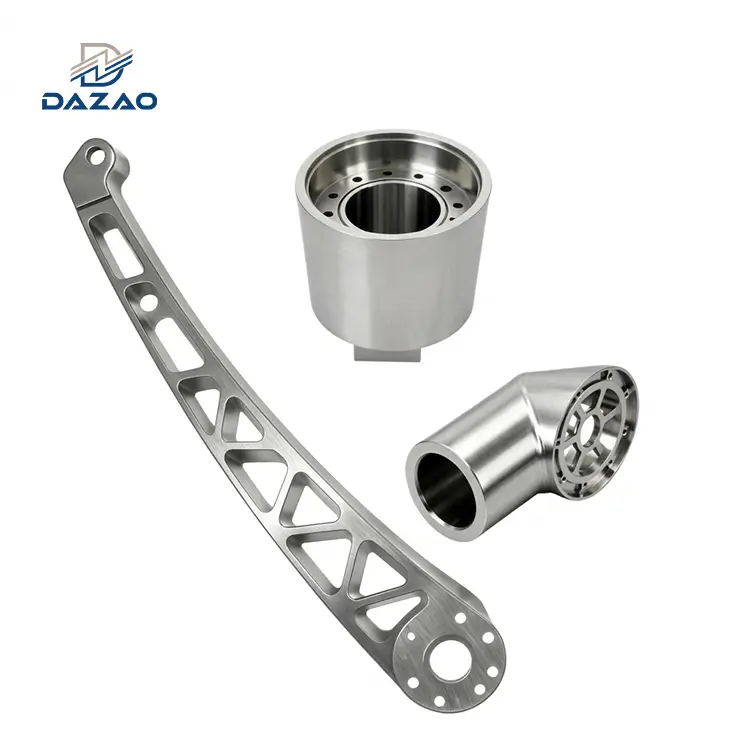
Precision 5-Axis CNC Machining for Quadruped Robot Structural Parts
Monolithic billet milling with ±0.005mm bearing seat tolerances, stress-relieved thin walls, and zero-backlash joint alignment.
Core Engineering Bullet Points:
Concentricity: Bearing bore runout controlled within ≤0.010mm.
Prototyping: 10-day turnaround for functional testing assemblies.
Tolerance: Critical dimensions held to ±0.005mm via 5-axis milling.
Stress-Relief: Multi-stage thermal cycling prevents impact fracture.
Weight Reduction: Topology optimization achieves 40% mass reduction.
Metrology: 100% CMM dimensional reports and material MTRs supplied.
Order Flexibility: Low volume production CNC machining robotics from 1 unit.

Kinematic Machining Capabilities for Dynamic Robotic Assemblies
Eliminating internal porosity, dynamic fatigue fracture, and axial misalignment through monolithic multi-axis fabrication.
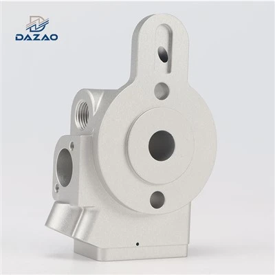
Xiamen Dazao Machinery specializes in precision 5-axis CNC machining quadruped robot parts engineered for autonomous bionic quadrupeds, robotic dogs, and industrial multi-legged platforms. Utilizing high-precision simultaneous 5-axis CNC machining centers, we manufacture monolithic structural components, bionic lower leg assemblies, hollow upper thighs, harmonic/cycloidal actuator housings, and integrated central chassis frames.
Our production protocols resolve structural failure modes common in high-dynamic robotics: high-velocity torsional deflection during dynamic gaits, stress-concentration cracks at thin-walled bionic transitions, and actuator transmission backlash caused by bore runout. Every component is machined directly from wrought aerospace-grade AL7075-T6 billet, AL6061-T6, or Grade 5 Ti-6Al-4V titanium machining to guarantee zero internal porosity and maximum dynamic yield strength.
5-Axis Continuous Multi-Axis Manufacturing Workflow:
Solid Billet
(7075-T6 / TC4)
1
>>
Directional Toolpathing (Stress-Aligned Cutting)
2
>>
Single-Setup 5-Axis Milling
(Bores, Shells, Flanges)
3
>>
Multi-Stage Thermal Stress-Relief
4
>>
Air Gauging & CMM Verification
(≤0.01mm Concentricity)
5
>>
Dynamic Fit Validation (Zero Backlash Transmission)
6

Engineering Specifications & Precision Machining Parameters
Dimensional boundaries, geometric tolerances, and surface roughness limits for high-speed robotic limbs.
|
Technical Parameter |
Engineering Limit & Tolerance Envelope |
Metrology Verification Method |
|
Standard Materials |
AL6061-T6, AL7075-T6, AL6082-T6, Ti-6Al-4V (Grade 5) |
Optical Emission Spectrometry & Mill MTR |
|
Maximum Machining Envelope |
850 mm x 700 mm x 500 mm (5-Axis Turn-Mill) |
Renishaw High-Resolution Linear Scales |
|
Linear Dimensional Tolerance |
±0.005 mm (Actuator Bores), ±0.020 mm (Profiles) |
Zeiss CMM & Multi-Jet Air Gauging |
|
Hole Feature Capability |
Custom blind hole CNC machining robot parts (M1.6–M12) |
Go/No-Go Thread Plug & Depth Gauges |
|
Concentricity & Coaxiality |
≤ 0.010 mm (Bearing Pocket to Pilot Datum) |
Lever Dial Indicators & CMM Cylindricity Scan |
|
Surface Roughness (Ra) |
Ra 0.4 µm (Bearing/Seal Seats), Ra 0.8 µm (Profiles) |
Contact Diamond Stylus Profilometer |
|
Thermal Treatment Protocol |
3-Stage Stress-Relief Cycling & Vibratory Stabilization |
Metallurgical Hardness & Microstructure Testing |
|
Surface Coating Systems |
MIL-A-8625 Type II / Type III Hardcoat Anodize (50 µm) |
Non-Destructive Eddy-Current Thickness Meter |
|
Fit Clearances & Dynamic Mating |
ISO H7/g6 Transitional Fits; Master Spline Coupling |
Plug Gauges & Physical Master Mating |
|
Prototype Turnaround Time |
10 Working Days (Includes CMM Inspection Pack) |
Scheduled CAM Cell Production Tracking |

Empirical Root Cause Analysis and Machining Corrective Actions
Practical machining corrections derived from dynamic gait testing, drop impact failures, and harmonic drive wear.
Case Study 1: Resolving Drop-Shock Tibia Fracture via Directional Stress-Relief Toolpathing
· Engineering Root Cause: Standard perpendicular 3-axis milling paths created microscopic tool marks across a 2.0mm thin-walled topological section. Under dynamic drop-shock testing, these tool marks acted as stress concentration points, causing fatigue fracture at the tibia transition.
· Machining Correction: Reprogrammed toolpaths to follow structural load vectors continuously using 5-axis contouring. Implemented pre-finish thermal stress-relief annealing and mandatory drop-weight impact validation on all first articles.
· Verified Metric Gain: Dynamic shear yield threshold increased by 40%; zero fractures recorded over 100 consecutive high-acceleration landing cycles.
Case Study 2: Eliminating Harmonic Drive Backlash via Single-Setup Concentric Milling
· Engineering Root Cause: Machining the internal stator bore and outer locating pilot in two separate clampings introduced 0.050mm cumulative runout. This eccentricity caused transmission binding, gear teeth wear, and a 0.2° joint positioning error during robot locomotion.
· Machining Correction: Converted all leg actuator housings to single-setup turn-milling operations. Internal bearing pockets, harmonic mounting faces, and seal grooves are now machined in one continuous multi-axis operation.
· Verified Metric Gain: Actuator housing runout is held within ≤0.010mm; harmonic drive efficiency improved by 5% with zero mechanical binding.
Case Study 3: Overcoming High-Velocity Chassis Twist Through Load-Path Topology Retention
· Engineering Root Cause: Aggressive pocketing to hit arbitrary weight targets removed excessive internal material, lowering the chassis polar moment of inertia and causing >10mm footfall trajectory deviations at 2.0 m/s speeds.
· Machining Correction: Executed DFM topology optimization with the customer. Retained continuous internal diagonal ribs aligned with leg mounting reaction forces while clearing weight from non-stressed webs.
· Verified Metric Gain: Torsional stiffness increased by 60% with only a 5% net mass addition, restoring high-speed directional tracking accuracy.

Five-Axis Monolithic Billet Milling vs Conventional Fabrication
Direct engineering comparison between multi-axis billet machining, structural welding, and die casting.
|
Structural Property |
5-Axis Monolithic Billet Milling |
Welded Aluminum Tubular Frames |
Die-Cast Aluminum Enclosures |
|
Internal Material Integrity |
100% Dense Wrought Billet (Zero Voids) |
Heat-Affected Zone (HAZ) Weakness |
Internal Micro-Porosity & Inclusions |
|
Achievable Geometric Tolerance |
Linear ±0.005mm; Coaxiality ≤0.010mm |
Thermal Distortion >0.150mm |
Draft Angle Limits; ±0.080mm |
|
Dynamic Impact Fatigue Life |
High Cyclic Shock Resistance |
Weld Seam Cracking Under Drop Impact |
Low Impact Resistance; Brittle Fracture |
|
Tooling Investment & NRE |
$0 Die Investment (Direct 3D CAD/CAM) |
High Welding Fixture Fabrication |
8,000–8,000– 25,000 Hard Die Tooling |
|
Design Iteration Speed |
10-Day Drawing Revision Turnaround |
3–4 Weeks Fixture Re-Alignment |
6–8 Weeks Mold Modification Delay |

Component Structural Geometry & Material Selection Guide
Balancing dynamic yield strength, modulus of elasticity, and weight reduction across functional robot assemblies.
· Bionic Tibia & Foot Terminals: High dynamic impact zone. Recommended Material: AL7075-T6 with multi-stage thermal stress-relief. Engineering Note: Maintain wall thickness ≥1.8mm at topological transitions to prevent dynamic shear rupture.
· Actuator & Harmonic Drive Shells: High coaxiality transmission zone. Recommended Material: AL6061-T6 or AL7075-T6 machined in a single clamping setup. Engineering Note: Bearing seats must include relief grooves for precise snap-ring and bearing seating.
· Femur & Hollow Upper Linkages: High bending moment during high-speed gait. Recommended Material: AL7075-T6 with internal webbed reinforcement. Engineering Note: Avoid sharp internal pocket transitions; specify a minimum corner radius of R1.5mm.
· Integrated Main Body Chassis: High torsional rigidity zone. Recommended Material: AL6061-T6 for standard units or Ti-6Al-4V for heavy-payload industrial platforms. Engineering Note: Orient main stiffener ribs parallel to front-and-rear hip drive axes.

Quality Assurance Metrology & Verification Standards
Closed-loop inspection protocols guaranteeing micro-inch accuracy from raw billet certification to final assembly.
Our quality management system is certified to ISO 9001:2015. Every batch follows a rigorous inspection sequence:
1. Incoming Material Verification: Chemical composition verification via optical emission spectrometry; all raw material test reports (MTR) are cataloged for full lot traceability.
2. First Article Inspection (AS9102 Standard): 100% geometric dimensional verification on a Zeiss 3D coordinate measuring machine verification platform before volume machining runs.
3. In-Process Runout & Bore Gauging: Multi-jet pneumatic air gauging for H7 bearing seats and calibrated thread plug verification for all custom blind hole CNC machining robot parts.
4. Mechanical Structural Testing: First-article dynamic drop tests for limb components and static torsional stiffness checks for main chassis frames.
5. Post-Surface Treatment Inspection: Eddy-current coating thickness verification for MIL-A-8625 Type III hardcoat anodizing to ensure internal bearing tolerances are maintained.

Industrial Deployment & High-Dynamic Operating Environments
Proven operational readiness across demanding field robotics, tactical systems, and bionic research platforms.

Autonomous Quadruped Patrol Platforms
Sealed joint enclosures and high-yield leg linkages engineered for continuous rough-terrain industrial inspection.

Cinematic Dynamic Quadruped Rigs
High-precision joint mounts and camera-stabilizing brackets that eliminate motor vibration harmonics.

Industrial EOD & Hazardous Duty Robots
Heavy-duty titanium Grade 5 knee linkages and high-torque cycloidal reducer shells for extreme payloads.

Chemical Plant Inspection Units
Corrosion-resistant Type III hard-anodized motor frames and IP67-rated bionic robot structural assemblies.

Academic Dynamic Locomotion Testbeds
Ultra-lightweight hollow linkages and chassis frames for high-acceleration gait optimization.

Robotic Exoskeletons & Biomechanical Joints
Compact, low-backlash joint couplings and precision structural actuator brackets.
FAQ for Robotics Hardware Designers

01.How do you prevent thin-wall warping when machining AL7075-T6 bionic robot legs?
02.How is bearing bore H7 tolerance maintained after Type III hardcoat anodizing?
03.Why use monolithic AL7075-T6 billet over carbon fiber tubes for quadruped legs?
04.How do you eliminate rotational runout in custom harmonic actuator housings?
05.How do you prevent thread stripping in aluminum robot leg joints during dynamic drops?
06.When should Ti-6Al-4V titanium be selected over AL7075-T6 for quadruped joints?
Rapid Engineering Review & Prototyping Request
Submit your CAD models for 24-hour DFM manufacturability feedback and line-item manufacturing quotations.
Submit your 2D and 3D CAD models (STEP, IGES, or DXF) to our robotics engineering team.
We deliver a complete DFM assessment, tolerance verification report, and quotation within 24 hours.
Contact Us

Hot Tags: precision 5-axis cnc machining quadruped robot parts,custom quadruped robot legs cnc machining,robot dog actuator housing aluminum fabrication,bionic robot structural parts cnc service,precision cnc machined robot joint components, CNC Machining Aluminum Parts, CNC Machining Metal Parts, CNC Machining Six Axis Robotic Accessories, cnc milling parts, CNC Plastic Parts, Precision CNC Milling Parts