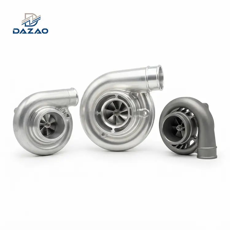
5-Axis CNC Machining Billet Aluminum Turbocharger Compressor Housings
Direct-milled monoblock compressor housings engineered for maximum aerodynamic boost efficiency, zero internal porosity, and verified surge suppression.
Core Engineering Features:
Volute flow path profile deviation: ≤0.02mm.
Internal surface roughness: Ra ≤1.2μm.
Zero porosity solid forged 6061-T6 & 4032 billet.
Functional anti-surge ported shroud execution.
Pre-calculated thermal clearance compensations.
10-day rapid prototype delivery without tooling.
100% CMM volumetric surface scan FAI reports.

Precision Billet Turbo Compressor Housing Machining Capabilities
Multi-axis simultaneous milling engineered to eliminate casting porosity and deliver exact volute aerodynamic profiles.
Monoblock 5-axis CNC milling of custom billet aluminum compressor housings supports tier-1 performance brands, motorsport teams, and high-pressure forced induction developers. Leveraging specialized precision CNC machining services, machining compressor covers directly from solid forged aluminum blanks (6061-T6, 4032) eliminates subsurface porosity, air pockets, and structural grain irregularities inherent in cast alternatives.
Multi-axis toolpaths generate continuous internal volutes and precise inducer profiles that stabilize air mass delivery across boost ranges from 1.0 bar to 3.5+ bar. Operating as a dedicated custom CNC machined turbo housing parts supplier, production capabilities range from 3D reverse engineering to small batch CNC machining turbo housings without tooling setup delays.

Root Cause Failure Analyses and Manufacturing Corrective Protocols
Practical engineering resolutions derived from real-world dyno and high-pressure track testing failures.
Street Performance Volute Toolpath Seam Elimination for Boost Efficiency
· Failure Context: A performance brand ordered direct replacement upgrade covers. Internal volutes were initially machined using partitioned 5-axis tool orientations. While visually acceptable, microscopic seams formed where tool vectors intersected along the scroll.
· Dyno Result: Dynamometer testing revealed boost pressure measured 8% below theoretical design output, along with a 6% drop in overall compressor efficiency caused by boundary-layer turbulence.
· Corrective Protocol: Toolpaths were transitioned to continuous 5-axis contour sweeps, eliminating tool repositioning within the volute. A secondary fluid abrasive smoothing process was added to maintain internal surface roughness at Ra ≤1.2μm. First articles undergo 3D CMM blade-passage scans requiring continuous profile deviation ≤0.02mm. Re-machined housings recovered 98%+ of modeled aerodynamic efficiency.
Motorsport Anti-Surge Port Shroud Geometry Stabilization
· Failure Context: An Australian drift team ordered billet covers with custom ported shrouds. Annular bleed slots were machined directly to customer prints without functional aerodynamic evaluation.
· Track Test Failure: Under high boost, the engine encountered violent compressor surge in mid-RPM throttle transitions, causing severe intake pressure fluctuations.
· Corrective Protocol: An engineering review standard for anti-surge structures was implemented. Instead of machining raw prints without verification, engineering recalculates slot entry angles, bypass area ratios, and bleed port placement against targeted compressor maps. Every prototype undergoes bench validation to verify surge margin stability from 1.8 bar to 3.2 bar.
Dynamic Thermal Expansion Compensation for Zero Blade Rubbing
· Failure Context: A high-pressure racing turbo housing was machined to strict ambient-temperature tolerances matching the customer's wheel inducer profile.
· Track Test Failure: After 15 minutes of continuous full-load track operation, differential thermal expansion between the aluminum housing and the compressor wheel closed the running gap, resulting in blade tip contact and hardware failure.
· Corrective Protocol: A dynamic thermal compensation protocol was implemented. Toolpaths integrate temperature-compensated expansion offsets derived from material coefficients and boundary heat transfer calculations. Every first article requires physical dual-state (ambient and elevated temperature) fit verification with the target wheel.

Aerodynamic Milling Protocols for High-Boost Compressor Housings
Standardized manufacturing methods designed to surpass conventional casting limitations in boost stability and surface finish.
1. Continuous 5-Axis Toolpath Volute Profiling: Utilizing continuous 5-axis CNC milling centers, toolpaths traverse the entire scroll volume in an uninterrupted sweep. Eliminating tool-retract points removes the micro-ridges that cause aerodynamic boundary-layer separation and pressure drops.
2. Operational-Matched Ported Shroud Architecture: Anti-surge bleed paths are configured with exact entry angles and chamber volume ratios to extend usable mass flow ranges without efficiency penalties.
3. Thermal Growth Offset Compensation: Blade clearances are machined with pre-compensated offsets to preserve target running gaps across operating cycles up to 3.5+ bar.

Technical Specifications and Machining Tolerances
Tight-tolerance dimensional and surface finish specifications for high-load forced induction assemblies.
|
Parameter |
Standard Specification |
High-Performance Option |
|
Material Grades |
Al 6061-T6 (Forged Billet) |
Al 4032 (High-Silicon Forged Billet) |
|
Machining Process |
5-Axis Simultaneous CNC Milling |
5-Axis Milling + High-Flow Hand Polish |
|
Housing Diameter Range |
80 mm – 350 mm |
350 mm – 500 mm (Custom Large Frame) |
|
Volute Profile Tolerance |
±0.025 mm |
±0.015 mm (Laser CMM Verified) |
|
Inducer / Exducer Tolerances |
±0.010 mm |
±0.005 mm |
|
Internal Surface Finish |
Ra ≤ 1.6 μm |
Ra ≤ 0.8 μm – 1.2 μm |
|
Mounting Face Flatness |
0.01 mm |
0.005 mm |
|
Surface Treatments |
Glass Bead Blasted, Raw Deburred |
MIL-A-8625 Type II Clear Anodized / Type III Hardcoat |
|
Target Pressure Range |
1.0 bar – 2.2 bar |
2.2 bar – 3.5+ bar |
|
Prototype Lead Time |
10 Business Days |
7 Business Days (Expedited DFM) |

Alloy Selection and Volute Architecture Matrix
Engineering guidelines for matching billet alloy grades and internal scroll configurations to specific operating pressures.
· Forged 6061-T6: Standard structural alloy for precision CNC aluminum parts and upgrade housings. Combines 276 MPa tensile yield strength with low density and uniform anodizing response. Suitable for street configurations and moderate motorsport boost duties up to 2.2 bar.
· Forged 4032: High-silicon alloy engineered with a lower coefficient of thermal expansion and elevated fatigue strength under thermal stress. Recommended for sustained high-boost racing applications exceeding 2.5 bar where dimensional stability is mandatory.
· Standard Smooth Volute: Optimized for steady-state mass flow and maximum pressure recovery in focused engine power bands.
· Integrated Anti-Surge Ported Shroud: Widens the usable operating envelope on large compressor trims, protecting compressor components from high-load low-RPM stall.

Forged Billet CNC Milling Versus Conventional Aluminum Casting
Structural, aerodynamic, and lead-time comparison between solid-machined billet and foundry cast housings.
|
Metric / Feature |
Forged CNC Billet Housing |
Cast Aluminum Housing |
|
Structural Integrity |
100% dense; zero porosity |
Micro-porosity & inclusions |
|
Pressure Capability |
3.5+ bar continuous rating |
Risk of fatigue cracking |
|
Flow Path Accuracy |
Profile error ≤0.02mm |
Core shifts up to ±0.5mm |
|
Volute Surface Finish |
Ra ≤1.2μm (milled/polished) |
Ra 3.2 - 6.3μm (as cast) |
|
Tooling & NRE Cost |
Zero tooling investment |
High foundry pattern costs |
|
Weight Optimization |
10-15% thinner walls |
Extra thickness needed |

Dimensional Metrology and Aerodynamic Inspection Standards
Multi-phase quality control tracking material composition, profile deviations, and running tolerances.
· Raw Stock Material Certification: Every forged billet lot undergoes optical emission spectrometry and ultrasonic flaw detection to confirm alloy integrity and grain structure.
· CMM Flow Path Inspection: Multi-axis CMM units scan internal volute profiles against native CAD STEP files, maintaining continuous profile tolerances within ±0.02mm.
· Wheel Fitment Verifications: Housings undergo physical coordinate verification against mating compressor wheel dimensions to maintain specified cold and hot tip running gaps.
· Surface Roughness Profilometry: Contact stylus profilometers verify that critical gas path surfaces satisfy specified Ra limits prior to shipping.
End-to-End Production Verification and Delivery Protocol
Structured manufacturing sequence from CAD validation to export-compliant packaging.
1. CAD & Technical Parameter Review: Engineering reviews customer 3D models (STEP/IGS) and provides DFM feedback on wall sections, port angles, and clearance allowances within 24 hours.
2. CAM Strategy & Multi-Axis Programming: Toolpaths are generated using 5-axis continuous strategies to eliminate internal setup seams.
3. First Article Prototyping (10-Day Turnaround): Prototype housings are machined from solid billet stock, followed by CMM inspection and surface preparation.
4. Batch Production & Traceability: Production lots are scheduled on multi-axis machining centers with routine tool-wear compensation.
5. Surface Finishing: Selected finishes, such as glass bead blasting or MIL-A-8625 clear anodized finishes, are applied and measured.
6. Protective Packaging & Global Logistics: Housings are secured in custom high-density EPE foam inserts within reinforced cartons, supported by DDP, FOB, or CIF terms.
Target Applications and High-Pressure Propulsion Platforms
Field-proven deployments across motorsport, aerospace, marine, and high-performance powertrain systems.

Aftermarket Performance Upgrades
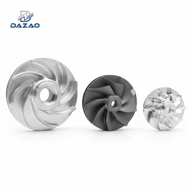
Direct-fit compressor housings engineered for bolt-on performance turbo kits and complementary billet water pump impellers.

Professional Motorsport Platforms
High-pressure competition units deployed in circuit, rally, and drag racing series.

Marine Powerplants
Clear-anodized marine-grade turbo covers resistant to saltwater corrosion and thermal stress.

Unmanned Aerial Propulsion (UAV)
Lightweight aluminum volutes engineered for high-altitude forced-induction engines.
Get A Quote for CNC Aluminum Turbocharger Compressor Housings
FAQs

01.Why do some aftermarket billet compressor housings flow worse than OEM cast covers?
02.Does an anti-surge ported shroud reduce boost pressure or low-end spool time?
03.Why does a compressor wheel scrape a billet housing only under high boost?
04.Does clear anodizing inside the volute change critical wheel dimensions?
05.When is forged billet aluminum necessary compared to cast aluminum housings?
06.Can a billet compressor housing be machined to fit an oversized wheel into a stock engine bay?
Submit 3D CAD models for immediate tolerance verification, thermal gap analysis, and quote turnaround within 24 hours.
Submit 2D drawings and 3D CAD files (STEP, IGS, X_T) directly to the engineering team for a detailed manufacturability review, thermal expansion evaluation, and quotation.
Contact Us

Hot Tags: billet aluminum turbo housing,5 axis CNC turbo compressor cover,precision turbocharger housing,anti surge compressor cover