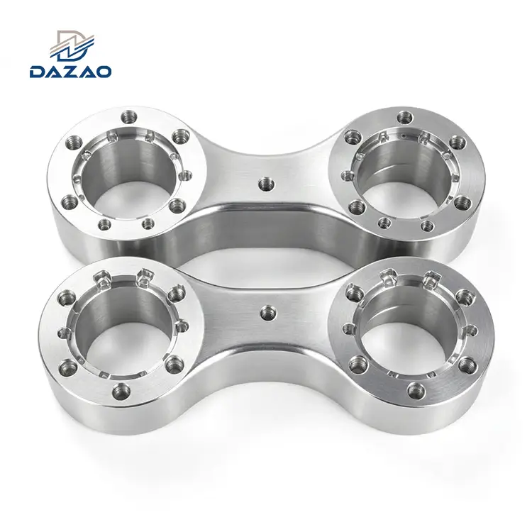
Precision CNC Machined Robot Joint Brackets
High-rigidity 7075-T6 aluminum structural components engineered for multi-axis articulation, minimal hysteresis, and long-term dimensional stability.
Core Engineering Features:
±0.005 mm precision tolerance on critical bearing seats.
Concentricity maintained within ≤0.02 mm across bores.
7075-T6 aerospace aluminum with 3-stage stress annealing.
Weight reduced by up to 40% via topology DFM analysis.
7-day prototype delivery; flexible orders from 1 unit.
100% CMM inspection report and material certs supplied.
Turn-mill single-setup setup removes re-clamping error.

Product Overview & Machining Capabilities
Advanced multi-axis milling and turn-mill processes delivering seamless structural integration and micron-level precision.
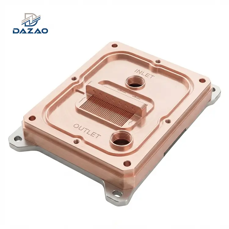
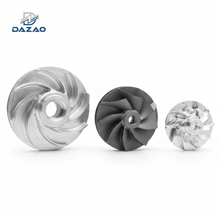
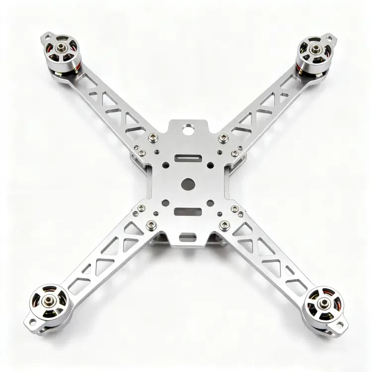
Xiamen Dazao Machinery manufactures precision CNC Machined Robot Joint Brackets using multi-axis simultaneous milling and integrated turn-mill centers. We process high-strength 7075-T6 aerospace aluminum, 6061-T6 alloy, and Grade 5 (TC4) Titanium billets into structural components for industrial robotic arms, collaborative robots (cobots), medical automation systems, and high-heat density liquid cooling plates. Our manufacturing footprint covers hollow arm joints, wrist articulation housings, and high-load base mounting frames.
By eliminating casting internal porosity and sheet metal assembly stack-ups, our solid-milled components deliver predictable structural integrity under high-frequency dynamic loading. We control internal residual stresses through dedicated thermal conditioning, ensuring critical tolerances remain dimensionally stable over extended operating lifetimes.
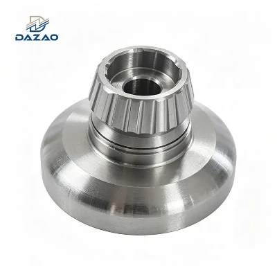
Lessons Learned from Mass Production
Real-world engineering post-mortems addressing thermal warpage, dynamic fatigue, and assembly backlash.
1. Hollow Arm Joint Concentricity Drift (7075-T6 Aerospace Aluminum)
· Initial Failure: A hollow joint bracket with a 3 mm wall thickness experienced a concentricity shift from ≤0.03 mm at factory sign-off to >0.08 mm after 14 days of room-temperature storage. This shift caused harmonic reducer binding during customer assembly.
· Root Cause Analysis: Single-pass rough milling released localized residual stresses stored within the cold-drawn 7075-T6 billet, leading to delayed spring-back and geometric warpage.
· Corrective Action: We implemented a 3-stage thermal stabilization protocol:
1. Rough milling leaving 1.5 mm stock.
2. Thermal stress relief annealing at 340°C for 2 hours, followed by controlled furnace cooling.
3. Semi-finishing, artificial aging at 120°C for 24 hours, and final alternating-face 5-axis finishing.
· Result: Post-machining dimensional drift dropped to ≤0.01 mm over a 6-month evaluation period, eliminating assembly binding.
2. Cobot Articulation Joint Fatigue Cracking Under Dynamic Load
· Initial Failure: A lightweight hollow joint bracket suffered structural cracking at internal sharp radii after 100,000 cycles during dynamic fatigue testing (15 kg payload at 2.5 m/s).
· Root Cause Analysis: Sharp internal transition corners (R0.5 mm) created localized stress concentrations exceeding the ultimate yield strength of the material during rapid deceleration stops.
· Corrective Action: We updated our Design for Manufacturability (DFM) verification steps:
1. Internal fillet radii were standardized to ≥R1.5 mm using specialized ball-nose end mills.
2. A controlled shot-peening step was introduced to induce compressive surface residual stresses across high-stress zones.
· Result: Sample brackets passed 300,000 continuous test cycles without micro-crack initiation, while achieving an additional 8% mass reduction.
3. Multi-Part Robotic Wrist Assembly Backlash Accumulation
· Initial Failure: A three-piece robotic wrist assembly (housing, shaft, and end-cap) exhibited 0.10 mm of cumulative angular backlash post-assembly, despite every component passing individual blueprint tolerances.
· Root Cause Analysis: Split-operation manufacturing (lathe turning followed by 3-axis milling on separate fixtures) introduced stack-up errors between datum faces and bearing journal centerlines.
· Corrective Action: We transitioned production to single-setup turn-mill multitasking CNC centers. All mating faces, pilot diameters, and bearing journals are now turned and milled in a single work-holding operation. Additionally, physical fit-up verification with master gauges is required for the first article of every batch.
· Result: Total wrist assembly backlash was reduced to ≤0.02 mm, eliminating hand-scraping during final assembly.

Technical Specifications & Manufacturing Limits
Comprehensive parameters defining dimensional limits, tolerances, surface finishes, and quality metrics.
|
Parameter |
Specification Standard |
Precision Capability |
|
Material Grades |
Aluminum 7075-T6, 6061-T6, 2024-T3; Titanium Grade 5 (Ti-6Al-4V); Stainless Steel 304/316L |
Material certificate with heat lot traceability included per batch |
|
Machining Processes |
4-Axis Milling, 5-Axis Simultaneous CNC Milling, Turn-Mill Multitasking |
Single-setup processing for complex geometries |
|
Max Workpiece Envelope |
800 mm × 600 mm × 500 mm |
Up to 1200 mm length for single-piece base structures |
|
Dimensional Tolerance |
Standard: ±0.02 mm |
Tight Tolerance: ±0.005 mm on critical bearing bores |
|
Position / True Coaxiality |
≤0.02 mm across opposite bore axes |
≤0.01 mm using dedicated multi-axis boring heads |
|
Minimum Wall Thickness |
1.2 mm (structural aluminum) |
0.8 mm (non-load-bearing shielding walls) |
|
Surface Roughness (As Machined) |
Ra 1.6 µm standard |
Ra 0.4 µm to Ra 0.8 µm on dynamic seal surfaces |
|
Surface Finish Options |
Type II/III Hard Anodizing (Clear/Black/Color), Chromate Conversion, Shot Peening, Electroless Nickel |
Salt spray resistance tested up to 480 hours per ASTM B117 |
|
First Article Verification |
Full CMM Inspection + Material OES Analysis |
100% dimension verification report provided prior to shipping |
|
Prototypes & Lead Times |
Rapid Prototyping: 7 Days |
Standard Production Batches: 10–15 Days |

Three Standardized Engineering Protocols
Proprietary DFM and stress-management workflows designed to eliminate invisible field failures.
Protocol 1: Low-Stress Thermal Conditioning for Dimensional Stability
To maintain dimensional stability over time, cold-worked aluminum alloys require controlled stress management. We submit all 7075-T6 hollow joint billets to intermediate thermal annealing cycles between roughing and finishing operations. This process relieves up to 92% of locked-in machining stresses, preventing post-machining movement during storage or operational heating cycles.
Protocol 2: Topology DFM & Structural Optimization
Before cutting metal, our engineering team evaluates customer CAD files through structural static and fatigue models. We identify non-critical material zones for pocketing and recalculate wall transitions to optimize stiffness-to-weight ratios. We modify sharp internal radii to distributed curvature geometries, increasing dynamic load capacity while reducing overall arm inertia.
Protocol 3: Assembly Tolerance Chain Control & Physical Fit-Up Verification
We analyze joint assemblies using worst-case and RSS (Root Sum Squared) tolerance stack methods. Instead of treating joint brackets as standalone components, critical dimensions are offset based on calculated mating interfaces. Every production run undergoes physical fit-up verification using ground master pin gauges and housing fixtures before surface treatment.

Honest Engineering Trade-offs: CNC Machining vs. Alternative Processes
An objective evaluation comparing billet CNC machining with high-pressure casting and sheet metal fabrication.
|
Feature |
CNC Machined Billet |
High-Pressure Die Casting |
Welded Sheet Metal |
|
Internal Integrity |
100% Solid (Zero Porosity) |
Risk of Gas Porosity |
Weld Seam Stresses |
|
Mechanical Strength |
High (Parent Billet) |
Medium |
Low-Medium |
|
Machining Tolerance |
±0.005 mm |
±0.10 mm |
±0.50 mm |
|
Tooling Upfront Cost |
$0 (Direct CAD Drive) |
$15,000 - $50,000 |
$2,000 - $5,000 |
|
Low-Volume Unit Cost |
Low (1 - 500 units) |
High |
Medium |
|
Material Choice |
7075-T6, 6061-T6, Ti-6Al-4V |
Limited Casting Alloys |
Weldable Alloys Only |
Strengths of CNC Machined Joint Brackets
· Superior Strength-to-Weight Ratio: Machining directly from extruded or forged 7075-T6 billet maintains full grain structure continuity, delivering higher yield strength (505 MPa) than die-cast aluminum alloys (e.g., A380 at 160 MPa).
· Zero Internal Void Risk: 100% dense material structure prevents hidden internal fatigue initiation points common in cast joint housings.
· No Tooling Investment: Direct CAD-to-CAM processing makes low-to-medium batch manufacturing economically viable without expensive tooling dies.
Trade-offs & Limitations
· Higher Material Scrap Rate: Machining deep hollow structures from solid billet results in higher raw material removal rates, raising material costs relative to near-net-shape casting for high-volume production (>10,000 units/year).
· Machining Lead Time for 7075 Alloy: High-strength 7075 alloy requires structured multi-pass milling and thermal annealing, extending processing times by approximately 20% compared to free-machining 6061 alloys.
· Surface Wear Limits: Bare aluminum lacks intrinsic sliding wear resistance; high-friction rotary contact surfaces require Type III hard-coat anodizing or hardened steel bushing inserts.

Technical Selection Matrix
Material grade, structural geometry, and payload guidelines to streamline component specification.
1. By Material Grade
· Alloy 6061-T6: Recommended for non-structural housings, light-payload cobot arms, and cost-sensitive assemblies. Good corrosion resistance and anodizing color consistency.
· Alloy 7075-T6: Recommended for primary load-bearing joints, dynamic wrist components, and high-frequency arm segments. Offers high yield strength and fatigue resistance.
· Titanium Grade 5 (Ti-6Al-4V): Selected for medical surgical arms and non-magnetic special applications requiring bio-compatibility or extreme weight reduction under high loads.
2. By Structural Configuration
· Hollow Arm Sections: Optimized for internal routing of power cabling and pneumatic lines. Requires multi-axis clearance and stress-relieved thin-wall milling.
· Wrist Articulation Housings: Features intersecting turned bores and precision face mounting patterns. Manufactured on turn-mill centers to maintain bore alignment.
· Base & Support Brackets: Heavy-section structural components designed to absorb overturning moments. Incorporates reinforced rib structures and deep-threaded anchor points.

Processing & Quality Assurance Workflow
End-to-end quality control measures ensuring raw material traceability and 100% CMM verification.
1. Raw Material Audit: Every incoming aluminum batch undergoes Optical Emission Spectrometry (OES) material composition testing and ultrasonic flaw detection.
2. First Article Inspection (FAI): Prior to running production batches, the initial part undergoes 100% dimensional measurement on a Zeiss CMM and physical fit-up verification with mating components.
3. In-Process Precision Checks: Critical bearing journal diameters and hole positions are inspected at key tool-wear intervals during production.
4. Final Dimensional Audit: Finished parts undergo CMM scanning to confirm geometric tolerances (flatness, perpendicularity, position, concentricity) against technical drawings.
5. Traceability & Packaging: Components are etched with part numbers and batch codes, wrapped in anti-static protective film, packed in custom EPE foam trays, and boxed in export-grade wooden cases.
Application Industries
High-stress automation sectors relying on lightweight structural joint brackets.

6-Axis Industrial Robots
Load-bearing joint housings, wrist assemblies, and custom six-axis robotic accessories for industrial manipulators.

Collaborative Robots (Cobots)
Thin-wall, weight-optimized joint frames designed to minimize motor torque demands and dynamic inertia.

Medical & Surgical Automation
High-precision, non-magnetic robotic articulation parts operating in cleanroom and surgical environments.

Autonomous Mobile Robots (AMR / AGV)
Structural suspension pivots, drive module brackets, and steering joints.
FAQs

01.How do you prevent thin-wall aluminum robot joints from distorting after CNC machining?
02.What true position tolerance can be held across opposite bearing bores in turned-milled wrist housings?
03.Why is 7075-T6 billet machining preferred over die casting for dynamic cobot articulations?
04.How do you protect thread profiles in high-torque aluminum joint brackets from stripping?
05.Which surface finish best improves dynamic fatigue life for aluminum robot joints?
06.How do you manage thermal expansion mismatches between steel bearing rings and aluminum housings?
Immediate DFM feedback and competitive rapid quotes powered by experienced mechanical engineers.
Need fast engineering feedback on your robot joint bracket design?
Upload your 2D/3D CAD files (STEP, IGES, or PDF) for a DFM evaluation and an itemized commercial quotation within 24 hours.
Contact Us

Hot Tags: CNC Machined Robot Joint Brackets,7075 aluminum robot joints,robotic brackets,5-axis CNC milling