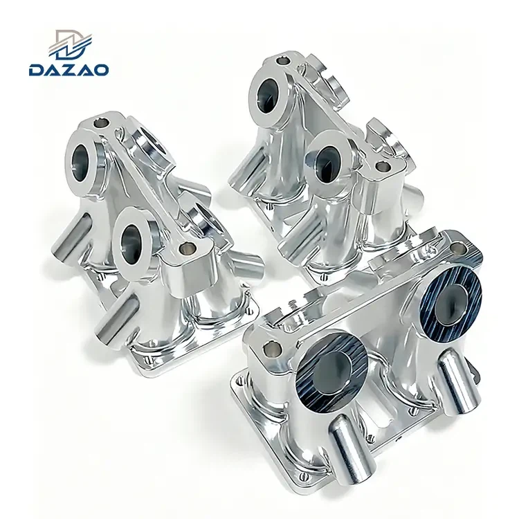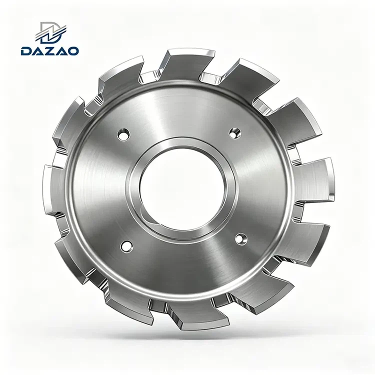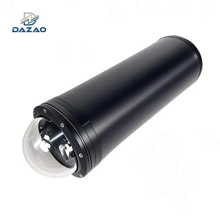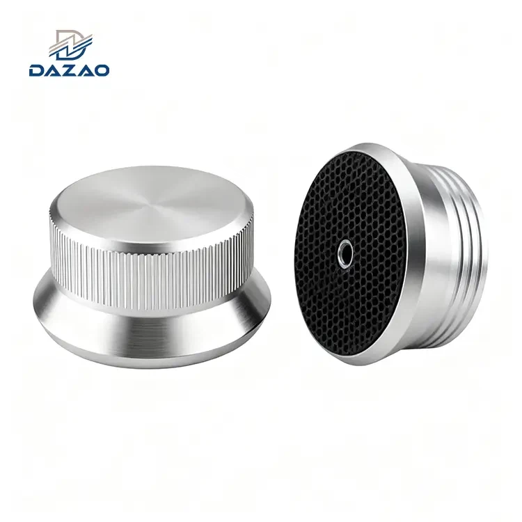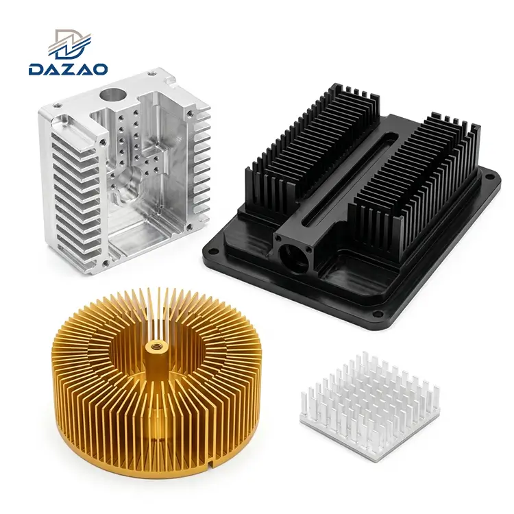
CNC Aluminum Heat Sink Precision Milling Service
Billet-machined thermal management solutions with certified flatness and zero internal porosity.
Core Engineering Features:
Custom CNC machined aluminum heat sink: ±0.02mm tolerance.
High-density pin fins with 15:1 aspect ratio capability.
Thermal interface flatness verified to ≤0.02mm range.
Anodizing thickness compensated during CNC precision milling.
Rapid prototype CNC aluminum heat sink shipped in 3 days.
BMS custom CNC aluminum heatsink for EV battery use.

CNC Aluminum Heat Sink Fabrication and Machining Capabilities
Precision 3-axis and 5-axis milling engineered to minimize interface thermal resistance.
Our CNC machining service utilizes high-precision 3-axis and 5-axis milling to fabricate highly conductive thermal solutions without porosity. Utilizing raw material grades like AL6061-T6 and AL6063-T5, we machine complex geometry profiles including pin-fin, comb-style, ultra-low profile, and integrated enclosure heat sinks. We optimize thermal conductivity by machining directly from solid billet, eliminating the joint thermal resistance common in assembled or brazed profiles.

Production Troubleshooting Case Studies and Engineering Adjustments
How we corrected dimensional and thermal failures to establish repeatable production yields.
Rather than relying on generic marketing claims, we verify our engineering capability through actual production problem-solving. Below are three actual case studies where we re-engineered our manufacturing processes to resolve critical thermal, dimensional, and geometric defects.
Technical Audit 1: Rectifying Thermal Interface Resistance in Roadway LED Assemblies
During initial production of outdoor high-power CNC aluminum heat sink for LED lighting assemblies, we utilized standard face-milling processes. While the outer physical dimensions met customer drawings, the thermal contact face registered a flatness deviation of approximately 0.08mm. During customer load-testing, 30% of the LED chips experienced junction temperatures exceeding rated limits, leading to rapid luminous decay.
We developed an in-house contact-surface calibration protocol. After the primary milling cycle, we introduced a secondary precision mirror-grinding pass to bring the flatness down to ≤0.02mm and surface roughness to Ra 0.8. We mandated a 100% inspection gate using optical flats and feeler gauges to verify coplanarity.
The thermal interface resistance decreased by 40%, reducing chip luminous decay rates by 70%. The customer has maintained a consistent monthly re-order schedule with zero subsequent thermal failures.

Technical Audit 2: Eliminating Hard Anodizing Fit Interference in EV BMS Housings
We received an order for a precision CNC machined aluminum heat dissipation housing designed for an electric vehicle Battery Management System (BMS). The specifications demanded black hard-anodizing. Initially, we machined the housings to nominal CAD dimensions before anodizing. This step ignored the 10–20μm oxide layer buildup, which restricted mounting hole diameters and caused interference at critical locking tab interfaces.
We established an active anodizing dimensional pre-compensation protocol. Based on the chemical bath parameters (standard vs. hard anodizing), we calculate expected oxide growth in advance. The CNC programming offsets are calibrated to enlarge bores and reduce outer profiles prior to surface treatment. Furthermore, we run identical batch parts in single-tank cycles to ensure uniform film deposition.
Post-anodizing assembly yield reached 100%, resolving the risk of part rejection after chemical treatment.

Technical Audit 3: Correcting High Aspect Ratio Fin Deflection in Telecom Modules
A telecommunication client specified a high aspect ratio CNC aluminum heatsink with pin fins measuring 20mm in height and 1mm in thickness (a 20:1 aspect ratio). Our initial conventional single-pass milling runs resulted in tool deflection and chatter, causing distorted fins with non-uniform thicknesses and poor verticality. This geometric deviation reduced the effective heat dissipation area by 18%, causing the thermal dissipation capacity to fail client standards.
We engineered a multi-pass reciprocating milling program, limiting the depth of cut (Ap) to ≤0.5mm per pass to minimize lateral cutting force. We combined this with active tool-radius compensation and integrated a post-roughing thermal stress-relief annealing stage.
Fin verticality was brought to ≤0.03mm, with total thermal dissipation surface area utilization exceeding 98%, enabling the components to pass all environmental wind-tunnel testing.

Proprietary Machining Protocols for High Performance Heat Sinks
Deflecting machining stress to preserve coplanarity and pin fin geometric accuracy.
These three proprietary processing protocols have been integrated into our standard operating procedures:
Thermal Contact Interface Planarization
· Process: Combined CNC face-milling with automated mirror-grinding.
· Standard: Surface roughness controlled to Ra ≤0.8; surface flatness maintained at ≤0.02mm.
· Verification: 100% flat-glass optical interference testing.
High Density Pin Fin Aspect Ratio Controls
· Process: Multi-step progressive milling coupled with dual-direction toolpaths.
· Standard: Achieve minimum fin thicknesses of 0.8mm and aspect ratios up to 15:1.
· Verification: Coordinate Measuring Machine (CMM) tracking of verticality (≤0.03mm tolerance) and pin pitch consistency.
Pre-Machining Dimensional Plating Compensations
· Process: Pre-machining compensation calculated against known plating thicknesses (5–10μm for standard anodizing; 10–25μm for hard anodizing).
· Standard: Outer diameters reduced and inner diameters expanded during raw milling so finished dimensions sit in the middle of the tolerance band after plating.
· Verification: Thread-go/no-go gauges and bore micrometers applied post-anodizing.

Mechanical Specifications and Thermal Tolerances
Verified metrology parameters matching strict international engineering standards.
|
Parameter |
Specification |
Verification Equipment |
|
Material Grades |
AL6061-T6, AL6063-T5, AL1060, AL5052 |
Spectrometer material analysis |
|
Machining Process |
3-Axis, 4-Axis, and 5-Axis CNC Milling |
CNC Machining Center |
|
Dimensional Tolerance |
±0.02 mm (up to ±0.01 mm on critical features) |
Mitutoyo Micrometers / CMM |
|
Surface Flatness (Base) |
≤0.02 mm |
Optical Flat & Feeler Gauge |
|
Surface Roughness |
Ra 0.8 to Ra 3.2 |
Profilometer |
|
Maximum Parts Envelope |
800 mm × 600 mm × 200 mm |
Vernier Calipers / CMM |
|
Minimum Fin Thickness |
0.8 mm |
Calipers / Optical Comparator |
|
Maximum Fin Aspect Ratio |
15:1 |
Coordinate Measuring Machine |
|
Surface Finishes |
Sandblasting, Wire Drawing, Anodizing (Standard & Hard), Laser Marking, Chromate Conversion |
Coating Thickness Gauge / Salt Spray Testing |
|
Lead Time |
3 Days (Prototype), 7–10 Days (Low-Volume Batch) |
Project Management Tracking |

Manufacturing Evaluation: CNC Milling vs Extrusion vs Die Casting
Quantifying thermal density and geometric freedom across fabrication methods.
While choosing the optimal forming process, engineers frequently evaluate options between pure machining, high-purity CNC brass and copper parts with high conductivity, and typical die-cast aluminum alloys.
|
Feature / Metric |
CNC Machined Billet |
Aluminum Extrusion |
Die-Casting |
|
Thermal Conductivity |
Excellent (100% density); no voids |
Good; linear grain structure |
Lower; prone to internal porosity |
|
Design Flexibility |
Unrestricted; complex pockets & variable 3D fin configurations |
Restrictive; constant 2D profile only |
High complexity, but restricted by draft angles |
|
Precision & Flatness |
±0.02 mm flatness directly machined |
Low precision; requires secondary milling |
Poor; requires secondary machining on critical surfaces |
|
Tooling & Mold Fee |
Zero mold fees; programming only |
High mold fees |
Extremely high tooling costs |
|
Lead Time |
3 days prototyping; immediate production |
4–6 weeks for die fabrication |
6–8 weeks for mold fabrication |
|
Low-Volume Cost |
Highly economical for 1–1,000 units |
Cost-prohibitive for short runs |
Cost-prohibitive for short runs |

Material Grade Engineering Guide: AL6061-T6 vs AL6063-T5
Balancing tensile strength against thermal conductivity for optimal operating life.
Selecting from our precision CNC machining materials is essential to balance mechanical strength with heat dissipation performance:
AL6061-T6
· Thermal Conductivity: ~167 W/m·K.
· Engineering Characteristics: High tensile strength, excellent structural rigidity, and low deformation risk during deep pocket milling.
· Optimal Use Cases: Structural custom CNC aluminum heatsink for EV battery management, heavy-duty industrial enclosures, and high aspect ratio fin modules requiring structural load-bearing capacity.
· Limitation: Slightly lower thermal performance compared to 6063.
AL6063-T5
· Thermal Conductivity: ~201 W/m·K.
· Engineering Characteristics: Higher thermal performance and superior anodizing color consistency.
· Optimal Use Cases: Standard comb-type profiles, CNC aluminum heat sink for LED lighting, and purely functional thermal dissipation plates.
· Limitation: Lower mechanical hardness; thin fin structures with high aspect ratios are more susceptible to deformation under high lateral machining stresses.

Thermal Profile Classifications and Surface Finishing Treatments
Integrated mechanical protection combined with high-emissivity chemical coatings.
Product Classifications
· Pin Fin Heat Sinks: Designed for omnidirectional airflow, delivering high surface area-to-volume ratios.
· Comb / Plate Fin Heat Sinks: Engineered for unidirectional forced-air cooling setups.
· Heat Dissipation Enclosures: Integrated designs merging structural chassis protection with cooling fins.
· Ultra-Thin Low-Profile Heat Sinks: Designed for tightly packed space constraints.
· Complex Multi-Axis Custom Parts: Custom geometries designed around existing system internal components.
Professional Surface Treatments
· Sandblasting: Standard pre-treatment to uniform surface texture (bead blasting).
· Wire Drawing (Brushing): Aligns surface grain for aesthetic appeal.
· Anodizing (Type II & Type III): Increases corrosion resistance, adds electrical isolation, and permits color matching (Black, Clear, Blue, Gold).
· Laser Engraving: Highly legible, permanent marking of serialization, logos, and part numbers.
· Chromate Conversion Coating (Alodine): Preserves electrical conductivity while preventing surface oxidation.

Critical Industrial Environments and Operating Scenarios
Protecting highly sensitive microelectronics in high-stress operational fields.
Our milled assemblies are engineered to perform in demanding, high-reliability conditions across six critical industrial sectors:

Telecommunications Infrastructure
5G macro-station power amplifiers and RF transmitter units requiring remote passive cooling in harsh outdoor conditions.

Automotive & EV Systems
High-vibration battery pack thermal balancing boards and motor traction inverter modules requiring high structural integrity.

Industrial Automation & Control
High-TDP motor drive systems, PLC control cabinets, and multi-axis servo controllers operating in dust-sealed environments.

High-Power Optoelectronics
Commercial high-bay luminaires, architectural stage projection systems, and agricultural grow light systems requiring low chip-junction temperatures.
Supply Chain Optimization and Project Delivery Milestones
Direct communication and rapid CAD iteration to accelerate physical testing phases.
We execute an optimized production sequence to transition your project from initial design to global delivery:
· CAD Inquiry Submission: Submit 3D files (STEP, IGS) to initiate a custom CNC milling pre-production review.
· DFM Analysis & Quotation: We verify geometries, check draft corners, compute wall-to-fin aspect ratios, and issue a fixed pricing breakdown.
· Materials & Programming Setup: Standardizing raw material billets, selecting cutting tools, and developing G-code sequences.
· CNC Rapid Prototyping (3 Days): Execution of short-run components without hard tooling, verified via FAI.
· Sample Approval: Delivery of initial physical verification samples to validate system-level integration.
· Mass Production Launch: Automated batch milling utilizing modular fixture holding plates for maximum throughput.
· Post-Machining Surface Finishing: Execution of sandblasting, chemical etching, or anodizing treatments.
· Final Inspection & Metrology Gate: Dimension verification, base flatness checks, and thread check operations.
· Export Packaging & Shipping: Finished assemblies are dispatched globally via FOB, CIF, or DDP agreements.
Metrology Standards and In-Process Inspection Operations
From raw material spectrometry to 100% optical interface verification.
To guarantee performance reliability in critical operational environments, we maintain a multi-tier quality gate system:
· Incoming Material Control (IQC): Every raw billet shipment undergoes spectrometer chemical composition testing. We verify material certificates and maintain full heat-number traceability.
· First Article Inspection (FAI): We mandate an FAI check during set-up initialization, tool changes, or program adjustments. No batch runs begin without sign-off on the FAI report.
· In-Process Quality Control (IPQC): Machining operators perform scheduled micrometric evaluations at 30-minute intervals, monitoring fin verticality, groove spacing, and wall thicknesses.
· Thermal Interface Verification: 100% of finished parts undergo optical flat planar checks to confirm the mounting face flatness remains within ≤0.02mm.
· Final Quality Control (FQC): Includes post-anodizing thread-go/no-go gauging and thickness testing of the oxide layer.
· Packaging and Damage Prevention: We utilize custom-molded polyethylene (PE) foam nests inside heavy-duty corrugated cartons to prevent fin deformation or cosmetic scratching during global transit.
International Logistics Agreements and Quality Assurances
Seamless customs processing, risk mitigation, and complete documentation compliance.
· Incoterms Supported: FOB, CIF, DDP (including customs clearance and duty payments directly to your facility).
· White-Label & Custom Branding: Neutral packaging, custom parts labelling, and laser-marked barcoding.
· Quality Indemnity: Full replacement warranty on any dimensional non-conformance, with return shipping costs covered by our facility.
· Engineering Documentation Package: Every shipment includes a Certificate of Conformance (CoC), material chemical report, dimensional inspection sheets, and optional thermal test validation logs.
Frequently Asked Questions: Regarding Thermal Management Machining

01.Can you customize a custom CNC machined aluminum heat sink?
02.Do you offer a CNC aluminum heat sink manufacturing service?
03.Can you produce a rapid prototype CNC aluminum heat sink?
04.Why should I choose a 6061 aluminum CNC milled heat sink?
05.Do you fabricate anodized CNC aluminum pin fin heat sink components?
06.What is your capability for a precision CNC machined aluminum heat dissipation housing?
Submit your 2D engineering drawings (PDF) and 3D CAD models (STEP, IGS, or Parasolid files) for a complete DFM review and a detailed quotation within 24 hours.
Contact our engineering team at erica@dazaocn.com to accelerate your thermal management project.
Contact Us

Hot Tags: CNC aluminum heat sink, custom CNC machined aluminum heat sink, CNC aluminum heat sink manufacturing service, 6061 aluminum CNC milled heat sink