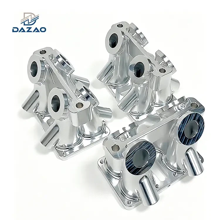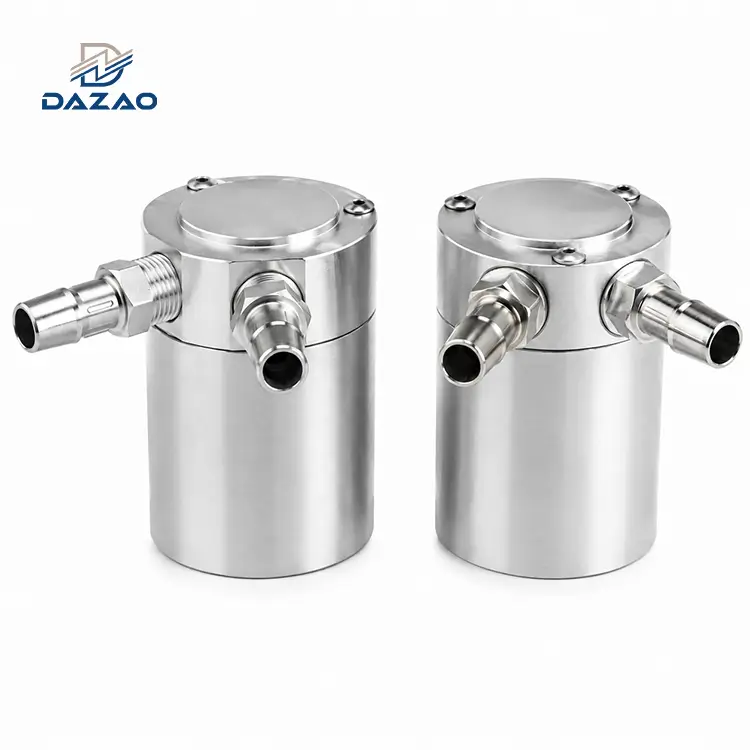
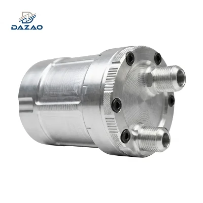
CNC Aluminum Racing Oil Catch Cans for High Boost Powertrains
Engineered from solid 6061-T6 aerospace billet to deliver continuous high-velocity crankcase blow-by separation.
Key Technical Specifications:
Solid 6061-T6 aluminum bar stock, multi-axis milled.
Multi-stage internal baffling stops blow-by oil bypass.
Precision single-point turned AN10 female ports.
Pressure-tested to 5.0 bar with zero joint leakage.
4-day rapid prototyping; production in 7–12 days.
Sub-assembly integration with drain valves and O-rings.
Zeiss CMM inspected to ±0.005 mm critical tolerance.
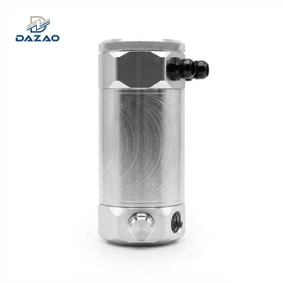
Engineered Billet Aluminum Oil Separation Capabilities
Multi-tier internal vapor coalescing technology eliminating intake valve carbon fouling under extreme manifold boost.
We produce high-performance oil separation assemblies engineered for high-boost, high-RPM motorsport and aftermarket powertrain platforms. Every unit is subtractively machined from solid 6061-T6 aluminum billet using advanced 5-axis CNC aluminum machining services. This single-setup method eliminates the material porosity, thin-wall cracking, and structural separation risks typical of cast or stamped canisters.
Designed to isolate crankcase blow-by, suspended oil vapor, and condensation from entering the intake plenum, our CNC machined aluminum oil separator assemblies protect intake valves from carbon accumulation and stabilize crankcase pressure. We supply global Tier-1 aftermarket brands, race engineering teams, and wholesale distributors with complete manufacturing services, offering material batch traceability, precision-machined port geometries, integrated multi-tier internal baffle arrays, and resilient surface finishing.
Comprehensive Technical Specifications and Tolerances
Dimensional limits, pressure ratings, and certified alloy standards for motorsport applications.
|
Parameter Dimension |
Engineering Specification |
Verification Method |
|
Raw Material Options |
Al6061-T6, Al7075-T6, Al6082-T6 Solid Billet Bar |
EN 10204 3.1 Mill Test Certificate / Spectrometry |
|
Manufacturing Process |
4-Axis / multi-axis CNC turn-mill centers, Single-Setup Indexing |
CNC Multi-Axis Program Verification |
|
Dimensional Tolerances |
General: ±0.05 mm; Critical Bores & Ports: ±0.005 mm |
|
|
Port Configurations |
Single In / Single Out, Dual Port (Dual In / Single Out), Quad Port |
Dedicated AN Thread Go/No-Go Plug Gauges |
|
Interface Thread Standard |
7/8-14 UNF-2B (AN10 ORB), 3/4-16 UNF-2B (AN8), 1-1/16-12 (AN12) |
Calibrated Pitch Micrometers & Thread Gauges |
|
Internal Baffle Geometry |
Multi-tier CNC-milled interleaved step plates, removable core |
Optical Profile Projector |
|
Operating Pressure Range |
Full Vacuum to 5.0 bar (72.5 PSI) continuous |
Pneumatic Pressure Decay Testing |
|
Surface Treatment |
MIL-A-8625 Type II Anodized (Black, Red, Blue, Clear, Custom) |
Eddy-Current Coating Thickness Gauge |
|
Surface Roughness |
Internal Bores: Ra 0.8 μm; External Profiles: Ra 1.6 μm |
Mitutoyo Surface Roughness Tester |
|
Sealing Interfaces |
Dual FKM (Viton) O-ring radial capture grooves |
Mitutoyo Optical Toolmaker Microscope |
|
Drain Mechanism |
Integrated 1/4" or 3/8" NPT/BSPP bottom port with quick-drain valve |
Functional Torque & Seal Inspection |
|
Prototyping Lead Time |
4 Business Days |
Expedited Fast-Track Cell |
|
Mass Production Lead Time |
7 to 12 Business Days (Batch size dependent) |
Production Scheduling ERP Tracked |

High Boost Engineering Resolutions and Failure Analysis
Real-world dynamometer and cold-weather corrective actions developed to prevent trackside failures.
High-Boost Turbocharged Blow-By Pass-Through Elimination
· Failure Analysis: A customer reported high-speed oil mist pass-through in an early prototype baffled oil catch can for forced induction under 2.5 bar boost conditions. High-velocity crankcase gas bypassed the single flat internal baffle plate, flooding the intake charge pipe.
· Root Cause: Inadequate expansion volume and lack of flow velocity reduction allowed microscopic oil droplets to remain suspended in the air stream.
· Corrective Action: We redesigned the internal assembly from a flat plate into an interleaved, multi-tier drop-down baffle system. By forcing the gas through three successive velocity drops and 90-degree directional changes, heavy oil droplets coalesce on the lower plates while scrubbed air escapes through the top port. Oil separation efficiency increased by 90% in dynamometer validation.
Cold-Climate Condensation Emulsion and Channel Freezing Mitigation
· Failure Analysis: Open-loop vent-to-atmosphere canisters shipped to a Nordic distributor suffered cold-weather emulsification. Water vapor and oil sludge froze inside the outlet channel, blocking crankcase venting and causing crankshaft seal blowout.
· Root Cause: Static horizontal vent channels acted as condensation traps during sub-zero cold starts.
· Corrective Action: We modified the internal discharge port geometry with a 15-degree downward self-draining slope and integrated a serviceable micro-mesh condensation separator. We instituted an engineering protocol advising closed-loop recirculation for extreme cold-climate deployments, eliminating sub-zero field failures.
Single-Point CNC Thread Turning for Leak-Free AN10 Seal Integrity
· Failure Analysis: A racing parts wholesaler faced field leaks when mating aftermarket AN10 braided hose adapters to standard machined 7/8-14 internal threads under sustained engine bay vibration.
· Root Cause: Tapping tools produced minor thread lead error and axial misalignment against the sealing face (>0.03 mm runout), preventing the O-ring from seating evenly against the 45-degree chamfer.
· Corrective Action: We replaced thread-tapping with single-point CNC thread-turning performed in the same chuck setup as the chamfer and face milling. Port coaxiality and perpendicularity are maintained within ≤0.008 mm. Every batch is verified using calibrated AN10 thread gauges and pressurized oil-leak fixtures.

Dynamic Fluid Dynamics and System Architecture
Purpose-built internal geometry designed for closed-loop PCV integration and open-loop track ventilation.
Closed-Loop PCV Integration Versus Open-Loop Track Ventilation
Closed-loop configurations route scrubbed gas back into the intake tract, requiring minimal internal airflow resistance (ΔP<0.05 bar) to preserve factory ECU vacuum dynamics. Open-loop vent-to-atmosphere canisters are optimized for extreme boost, high crankcase volume, and high flow velocity, incorporating integrated oil-slosh protection and auxiliary splash-guard filters. We machine flow channels customized specifically to the client's chosen operating model.
Multi-Stage Kinetic Velocity Drop Separation Technology
Conventional catch cans use generic, static mesh filters that saturate and fail under sustained high-manifold pressure. Our multi-stage separation architecture uses variable internal chamber cross-sections. When high-pressure blow-by enters the inlet, it undergoes a sudden pressure drop in the primary expansion zone, triggering mechanical separation of liquid oil from air. The secondary and tertiary stages trap residual micron-level aerosols before the gas stream reaches the outlet port.
Turnkey Platform Integration for Motorsport Engine Architecture
We maintain machining programs and physical fitment gauges across dominant performance engine platforms. Our universal aluminum catch can with AN10 fittings features standardized port pitch and mounting bolt circles adaptable to chassis-specific engine bays. We offer dedicated brackets, customized hose routing bosses, and balance ports for high displacement platforms, including our ready-to-run aluminum oil catch can kit for LS engine platforms.

Structural Billet Machining Versus Die-Cast and Stamped Alternatives
Material fatigue resistance, thread burst limits, and structural integrity under sustained boost.
|
Feature / Metric |
CNC 6061-T6 Billet Canister |
Conventional Die-Cast Canister |
Stamped / Welded Sheet Aluminum |
|
Material Integrity |
100% Solid Billet; Zero Porosity |
Prone to Internal Shrinkage Voids |
Thin-wall sheet (1.2–1.5 mm);fatigue-prone |
|
Burst Pressure Rating |
>25.0 bar(Body Structural Burst) |
8.0–10.0 bar |
4.0–6.0 bar (Joint Failure) |
|
Port Thread Rigidity |
CNC Single-Point Turned (No stripping) |
Cast threads; prone to cross-threading |
Welded bungs; thermal distortion |
|
Baffle Integration |
Machined Interlocking / O-Ring Sealed |
Loose Cast Partitions / Non-Sealed |
Spot-welded sheet; bypass leakage |
|
Vibration Resistance |
Extreme (Motorsport / Off-Road rated) |
Moderate (Risk of cracking at bosses) |
Poor (Heat-affected zone crack risk) |
|
Customization Flexibility |
Zero tooling cost; rapid CAD modification |
High tooling cost; rigid tooling |
Moderate tooling; high manual labor |

Six-Stage Metrology and Leak Verification Protocols
AS9102 dimensional verification, 5.0 bar pressure decay checks, and material lot traceability.
· Stage 1: Raw Material Validation: Optical Emission Spectrometry chemical assay verification for 6061-T6 bar stock to confirm chemical composition prior to cutting.
· Stage 2: First Article Inspection (FAI): Complete AS9102 dimensional verification on Zeiss Coordinate Measuring Machine metrology equipment before mass production release.
· Stage 3: CNC In-Process Metrology: Air-gauge bore verification for O-ring counterbores and thread plug gauging every 10 machined parts.
· Stage 4: Hydrostatic / Pneumatic Leak Testing: 100% batch testing where canisters are submerged under 5.0 bar pneumatic pressure to verify total sealing integrity.
· Stage 5: Surface Finish & Coating Inspection: Cross-hatch adhesion testing (ASTM D3359) and coating thickness measurement across all anodized lots.
· Stage 6: Final Clean-Room Cleanliness Protocol: Ultrasonic degreasing and particle wash testing to ensure zero machining chip or cutting fluid residue remains.

Demanding Motorsport and Powertrain Application Scenarios
High-load operating environments validated for maximum crankcase pressure stabilization.

Forced Induction Circuit Racing & Time Attack
Turbocharged and supercharged track vehicles running continuous high boost, requiring a high capacity racing oil breather tank and precision automotive CNC performance components to control crankcase surge.

Professional Drift & High-G Competition
High-lateral acceleration drift builds requiring a dual port billet aluminum catch can with baffle capture to prevent oil slosh and crankcase pressure buildup.

LS Engine Swaps & Restomod Builds
High-displacement V8 conversions utilizing an aluminum oil catch can kit for LS engine applications with vehicle-specific mounting brackets.

Direct-Injection (GDI) Intake Valve Protection
Daily-driven and tuned direct-injection vehicles utilizing a baffled aluminum catch can for turbocharged cars to prevent PCV-induced carbon build-up on intake valves.
FAQs

01.Will installing a catch can cause a drop in crankcase vacuum or trigger check engine codes?
02.How does the internal baffle prevent oil mist from being pulled into the intake under boost?
03.Why does oil-water emulsion freeze in catch cans during winter and how is it prevented?
04.What is the difference between single-port and dual-port configurations for high-horsepower engines?
05.Why do standard threaded AN fittings sometimes leak on billet cans, and how do you ensure a zero-leak seal?
06.How often must the internal baffle assembly be cleaned, and how does the drain valve simplify service?
Rapid 4-day prototyping and scalable volume production with comprehensive CMM reporting.
Stop blow-by contamination, fitting leakage, and delivery delays with our precision manufacturing infrastructure.
We deliver production-ready 6061-T6 billet aluminum catch cans built to your exact assembly drawings and performance criteria.
Contact Us

Hot Tags: CNC aluminum racing oil catch cans,billet aluminum baffled oil catch can,cnc machined aluminum oil separator,universal aluminum catch can with AN10 fittings