


Over 70 percent of precision machining delays, price surcharges, and prototype rejections originate from unverified CAD models and conflicting drawing notes. Executing a systematic CNC DFM checklist for engineers prior to RFQ submission eliminates non-standard tooling, minimizes setup rotations, stabilizes dimensional compliance, and guarantees a manufacturing ready CNC part design for production at Dazao.
Design Review for CNC Machined Parts Before RFQ and Production
Executing a thorough dfm cnc review separates functional production models from expensive geometric concepts. In precision manufacturing, raw CAD data often conceals geometric features that violate basic machining physics, leading to tool chatter, excessive cycle times, and dimensional rejection. At Xiamen Dazao Machinery, operating under ISO9001:2015 and IATF16949:2016 certifications since 2000, our precision CNC machining services prove that upfront design verification reduces manufacturing lead times by up to 45 percent while cutting unit component costs.
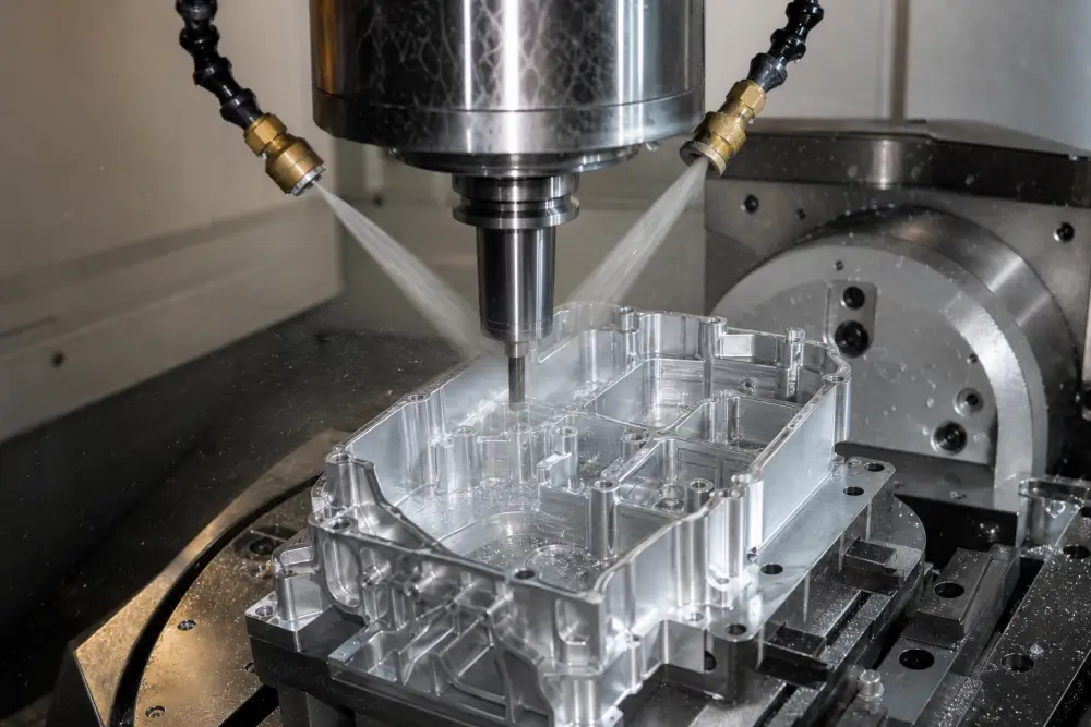
The True Cost of Unverified CAD: Why DFM CNC Reviews Prevent RFQ Delays and Scrap
A 3D model in modern CAD software does not account for cutting tool pressure, physical spindle clearance, thermal expansion, or residual stress within the raw stock. When an engineer submits an unverified model for quoting, the supplier must either price in the risk of specialized tooling and secondary setups or issue multiple engineering change requests.
A design stage defect fix requires approximately five minutes with zero cost impact. An RFQ stage engineering clarification causes two to four days of lead time delay. A prototype stage tool deflection failure results in direct material scrap and machining rework costs. A mass production dimensional shift leads to complete batch rejection and assembly line stoppages.
A structured CNC machining design review checklist bridges the gap between mechanical intent and shop floor execution. Dazao applies this standard to ensure that every dimension, radius, and datum structure directly supports efficient, repeatable subtractive manufacturing.
The Step-by-Step CNC Machining Design Review Checklist for Engineers
Step 1: Function and Material Specification
Selecting material requires balancing functional mechanical properties against machinability ratings. Specifying overly hard or exotic alloys where standard structural materials suffice multiplies cycle time and tooling overhead. Review our aluminum CNC machining cost analysis to understand how alloy selection shapes cycle time expenses.
|
Material Alloy |
Machinability Index (100 = AISI 1212) |
Cutting Speed Range (SFM) |
Typical Failure Mode if Misapplied |
|
Al 6061-T651 |
270 |
800 - 1500 |
Residual stress warping if non-stretched stock is used |
|
Al 7075-T6 |
200 |
600 - 1200 |
Stress corrosion cracking under high mechanical load |
|
304 Stainless Steel |
45 |
100 - 250 |
Work hardening from tool rubbing, leading to tap breakage |
|
316L Stainless Steel |
36 |
80 - 180 |
Severe burr formation on cross-drilled holes |
|
Titanium Ti-6Al-4V (Gr 5) |
22 |
40 - 100 |
Thermal tool degradation due to poor thermal conductivity |
|
Polyoxymethylene (POM/Acetal) |
300 |
500 - 1000 |
Elastic deflection during clamping and deep slotting |
Material stock form dictates baseline part economics. For extended alloy parameters, consult our aluminum alloy machining guide. Designing a component with a 50.8 mm maximum outer envelope from plate stock when standard cold-drawn bar stock is available increases raw material waste and machine hogging hours.
Step 2: Geometry, Pocketing, and Tool Reach Dynamics
Internal pocket geometry must accommodate standard rotating end mills. Detailed calculations are available in our CNC pocket design guide.
· Pocket Depth-to-Width Ratio: Restrict pocket depth to less than 4 times the internal tool diameter. Exceeding a 4:1 ratio requires reduced feed rates, produces tool deflection, and induces chatter marks on vertical walls.
· Internal Corner Radii: The internal corner radius must always be at least 15 percent larger than the radius of the milling tool. A 90-degree internal corner is impossible to machine with standard rotary milling. Review our breakdown on internal corner radius design for CNC milling to see how matching the exact tool radius forces the cutter to dwell in the corner, drastically increasing radial engagement, vibration, and cutter breakage risk.
· Wall Thickness Limits: Maintain a minimum wall thickness of 0.8 mm for aluminum alloys and 1.5 mm for structural plastics. Review our CNC wall thickness design principles to prevent cutting force vectors from generating taper errors where the top of the wall meets nominal dimension but the root is out of tolerance.
Step 3: Holes, Threads, and Micro-Feature Physics
Hole preparation requires strict adherence to standardized tool catalogs and clearance parameters.
· Standard Drill Diameters: Utilize standard metric drill increments. Non-standard diameters require custom ground tooling or circular interpolation with undersized end mills, inflating cycle times.
· Drill Depth-to-Diameter Aspect Ratio: Keep standard drilling depth under 5 times diameter. Review our deep hole drilling rules for CNC parts to understand why depths exceeding five times diameter necessitate specialized peck-drilling cycles, through-spindle coolant tooling, and gun drilling setups to prevent chip packing and hole runout.
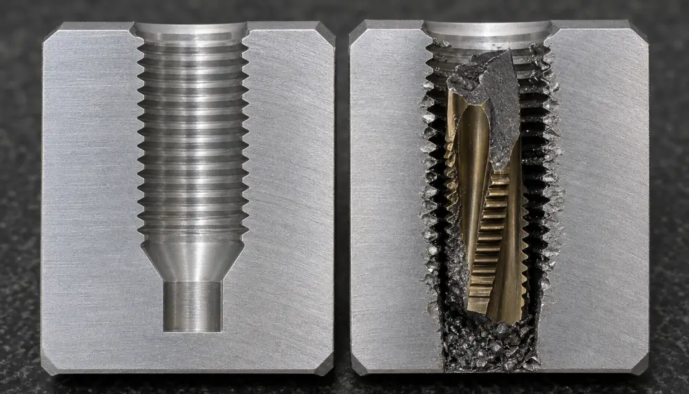
· Blind Tapped Hole Clearances: A blind tapped hole must always include extra depth in the pilot hole. Specify a minimum unthreaded pilot hole extension equal to 3 to 5 thread pitches past the final required thread engagement length. Review standard CNC thread design parameters to see how this accommodates tap lead chamfers and prevents chip packing from snapping taps inside the component.
· Flat-Bottom Holes: Standard drills leave a 118-degree or 140-degree conical point. Specifying true flat-bottom holes requires a secondary end mill plunging operation, adding tool changes and programming overhead.
Step 4: Tolerances, Datums, and GD&T Integrity
Over-tolerancing remains the single largest driver of unnecessary manufacturing expense. A robust design for manufacturability checklist for mechanical parts audits every tolerance block on the 2D engineering drawing.
· Standard Commercial vs Precision Tolerance: Apply ISO 2768-m (Medium) or ISO 2768-f (Fine) as general title block tolerances. Apply precision CNC machining tolerances of ±0.01 mm (±0.0004 in) only to critical bearing fits, dowel locations, and kinematic sliding interfaces.
· Datum Structure Alignment: Datums must correspond to physically accessible, rigid, and machine-probing surfaces. Specifying a datum on a flexible sheet metal flange or an unmachined curved cast profile prevents stable workholding and repeatable CMM alignment.
· Geometric Dimensioning and Tolerancing: Utilize position, flatness, and perpendicularity to control functional interfaces. Avoid stacking linear tolerances across multiple stepped features, which leads to tolerance accumulation and assembly failures.
Step 5: Surface Treatments and Dimensional Stack-Up
Surface finishing processes change the final envelope dimensions of machined parts. Failure to specify pre-plate or post-plate dimensions on the drawing causes immediate scrap during quality control. Explore our surface finishing and anodizing capabilities to align plating thicknesses with critical tolerance schemes.
· Type II vs Type III Hardcoat Anodizing: Standard Type II anodizing produces an oxide layer of 10 to 25 microns, with approximately 50 percent penetrating the substrate and 50 percent growing outward. Type III Hardcoat anodizing deposits 50 microns total, adding 25 microns of radial growth per surface (0.05 mm on diameter). Tight H7 bore tolerances will fail pin-gage inspection if machined to nominal before hardcoat.
· Masking Boundary Definition: Explicitly state areas requiring liquid masking or silicone plug insertion. High-tolerance ground dowel holes, grounding contact points, and fine internal threads (M3 and below) must be designated as masked areas on the 2D manufacturing drawing.
· Surface Roughness Specification: Default non-critical faces to Ra 3.2 µm (125 µin), which allows standard roughing-finishing passes. Restrict Ra 0.8 µm (32 µin) or Ra 0.4 µm (16 µin) callouts strictly to dynamic O-ring sealing grooves and fluid dynamic faces.
Step 6: Workholding Strategy and Setup Minimization
Every time a machinist loosens a vice, rotates a part, and reclamps, geometric error accumulates.
· Primary Clamping Flanges: Ensure the raw part design includes parallel clamping lands of at least 3 mm to 5 mm for vice jaw engagement across our CNC milling capabilities. Parts composed entirely of complex freeform contours require sacrificial clamping tabs or expensive custom soft jaws.
· Feature Orientation Alignment: Align internal cross holes, counterbores, and side slots along orthogonal planes. Features oriented at arbitrary compound angles force multi-axis indexing or multiple manual setups. Review 3-axis vs 5-axis CNC machining setup considerations to evaluate machine kinematics against fixturing costs.
Step 7: Metrology Feasibility and Quality Gate Definition
A dimension that cannot be inspected with standard metrology instruments cannot be verified for quality sign-off. Dazao applies certified CMM inspection protocols to guarantee traceable dimensional verification across all critical part datums.
· CMM Stylus Access: Deep, narrow internal grooves or undercut features must provide physical clearance for coordinate measuring machine ruby styli to make contact without shank interference.
· Free-State Inspection for Thin Components: When designing flexible polymer or thin-section structural parts, include drawing notes defining whether dimensional checks apply in the clamped or free-state condition.
· Quality Documentation Protocols: Specify requirement levels upfront, including First Article Inspection per AS9102, full CMM inspection point maps, material raw mill certificates, and surface treatment plating thickness certifications.
Step 8: RFQ Dossier and Data Alignment
A production-ready RFQ submission requires unified data across digital formats. Executing a strict DFM checklist before CNC machining quote submission ensures rapid pricing turnaround.
· 3D Native and Neutral Formats: Submit standard STEP AP242 or Parasolid (.x_t) files alongside native SolidWorks or Inventor CAD files. STEP AP242 preserves embedded geometric product definition and semantic GD&T data.
· 2D Engineering Drawing Sync: The 2D print represents the legally binding contract for threads, tolerances, surface finishes, and inspection criteria. Verify that revision levels on 2D prints and 3D files match exactly.
· Batch Volume and Delivery Schedules: State expected prototyping batch size, low-volume pilot run targets, and forecasted annual blanket orders to allow Dazao application engineers to design the most economical tooling and fixture strategy.
Three Hidden Machine Shop Failure Traps and Root-Cause Engineering Fixes
Standard online guides focus on general rules like wall thickness and corner radii. However, actual precision CNC operations encounter far more complex failure mechanisms that ruin production yields if ignored during design.
Trap 1: Asymmetrical Bulk Material Removal and Floor Warping
When machining deep, open-cavity structural enclosures, designers often pocket out more than 70 percent of the raw stock from one side while leaving a continuous thin bottom floor.
Standard hot-rolled or extruded aluminum plate contains non-uniform internal residual stresses locked into the material matrix during quenching. When a CNC spindle aggressively removes material from only one side, the compressive and tensile stress equilibrium across the cross-section is destroyed. The moment the part is released from the pneumatic vice or vacuum chuck, the thin floor flexes upward, generating severe longitudinal bow.
Dazao shop floor solutions include:
1. Mandating the use of stress-relieved, pre-stretched plate stock such as Al 6061-T651 or Al 7075-T651, where the 51 suffix designates mechanical stretching after solution heat treatment.
2. Maintaining a balanced floor-to-wall thickness ratio of at least 1:1, or integrating structural stiffening ribs across wide planar floors.
3. Including roughing and stress-equalization skim passes on both sides prior to final tolerance finishing.
Trap 2: 2D General Drawing Note Contradictions
Engineers frequently rely on broad drawing notes such as break all sharp edges 0.2 to 0.5 mm while maintaining razor-sharp 90-degree intersection edges in the corresponding 3D solid model.
Automated CAM software systems generate high-speed deburring and chamfering paths directly from native 3D geometry edges. If the 3D model contains sharp step corners adjacent to high-precision planar faces, automated chamfering tools will gouge the adjacent face. Conversely, optical inspection and CMM scanning systems checking the component will flag the edge as out-of-tolerance because the actual physical edge break deviates from the nominal solid edge profile.
Dazao shop floor solutions include:
1. Modeling critical chamfers and edge breaks directly within the 3D CAD geometry.
2. Differentiating on the 2D drawing between non-functional handling edges and critical functional edges where sharp intersections must be maintained for fluid sealing or linear bearing transitions.
Trap 3: Blind Tapped Hole Air Pocket Trapping and Acid Entrapment
Blind holes with deep internal threads present severe chemical contamination risks during post-machining chemical surface conversion processes.
When a component with blind tapped holes enters an anodizing or electroless nickel plating bath, trapped air pockets frequently prevent chemical solution from entering bottomed-out holes if the part orientation on the anodizing rack points downward. More critically, when submerged in sulfuric acid or bright dip tanks, aggressive acids become trapped in fine internal thread crevices. Rinsing tanks fail to dilute fluid locked in deep blind holes. Over subsequent weeks, residual acid slowly seeps out past the fastener, corroding internal threads and destroying assembly integrity.
Dazao shop floor solutions include:
1. Adding small cross-drilled relief vents (0.8 mm to 1.5 mm diameter) at the base of blind threaded cavities where structural constraints allow.
2. Mandating ultrasonic neutralization washing and forced-air drying cycles in technical drawing requirements when vent holes are structurally prohibited.
Lifecycle-Specific DFM Review: Prototype, Low-Volume, and Mass Production
Design criteria evolve as a component transitions from proof-of-concept prototyping to high-volume manufacturing. Applying mass-production constraints to an early functional prototype inflates non-recurring engineering costs. Releasing prototype-grade CAD directly into high-volume serial machining triggers severe cycle time bottlenecks.

Phase 1: Prototype Stage (Quantities: 1 to 20 Units)
The focus during prototyping is rapid physical validation of assembly fit and functional kinematics while avoiding specialized tooling investments.
· Tooling Standardisation: Eliminate custom form tools and specialized thread pitches. If an internal bore requires an undercut, consult our internal undercut design guide to evaluate whether a standard external retaining ring or bolt-down collar can serve the prototype testing phase.
· Secondary Setup Relaxation: If multi-axis milling is unnecessary for functional geometry, accept non-critical cosmetic machine marks on non-mating faces to allow single-setup machining.
· Relaxation of Non-Mating Finishes: Specify as-machined finishes (Ra 3.2 µm / 125 µin) on structural body faces. Reserve Ra 0.8 µm (32 µin) and specialized hard anodizing strictly for dynamic sealing surfaces and wear interfaces.
· Tolerancing Focus: Apply high-precision tolerances (±0.01 mm / ±0.0004 in) only to mating pin locations, bearing pockets, and motor pilot bores. Permit general linear tolerances of ISO 2768-m on all non-interface geometry.
Phase 2: Low-Volume Production and Pilot Runs (Quantities: 50 to 500 Units)
Low-volume manufacturing requires balancing unit cycle time against custom workholding fabrication costs. Performing a DFM review for CNC machined parts during this bridge phase stabilizes production fixtures.
· Standard Soft Jaw and Modular Fixturing: Design the external footprint of the component with parallel clamping datum surfaces to facilitate pneumatic vice setups with custom-machined aluminum soft jaws.
· Multi-Part Nesting Feasibility: Align external profiles so multiple components can be machined simultaneously from a single bar or plate billet on 4-axis horizontal machining centers or multi-station tombstones.
· Surface Treatment Lot Consistency: Establish clear chemical bath racking instructions on the manufacturing drawing. Variations in anodizing color or electroless nickel deposit rates across small production batches must be controlled via explicit coating thickness windows.
Phase 3: Mass Production (Quantities: 1,000+ Units Annually)
In mass production, saving fractions of a second per tool pass and stabilizing statistical process capability define project profitability. Conducting a CNC part design review before production freeze locks in these efficiency gains.
· Near-Net-Shape Raw Material Conversion: Transition from solid rectangular billet stock to custom aluminum extruded profiles or investment castings. Pre-forming the gross envelope reduces spindle hogging time, cuts raw material consumption by up to 60 percent, and minimizes tool wear.
· Statistical Process Capability: Tight tolerances must align with machine kinematic repeatability. Design non-symmetric tolerance bands to allow machinists to target the midpoint of the dimensional distribution, preventing scrap as cutting edges wear down.
· Automated Toolpath and CMM Optimization: Ensure all critical features can be accessed using standard probing routines on automated Coordinate Measuring Machines without manual part realignment.
The Pre-RFQ Manufacturing-Ready Engineering Verification Matrix
Engineers should review this checklist before releasing 3D solid models and 2D engineering drawings to Dazao or external machining suppliers.
|
Engineering Domain |
Specific Inspection Point |
Shop Floor Failure Consequence |
Defect Severity |
Corrective Design Action |
|
Cavity and Pockets |
Internal vertical corner radius vs cavity depth |
Tool chatter, surface gouging, premature end mill corner chipping |
Critical |
Specify corner radius R >= 1.15 x tool radius; limit pocket depth to <= 4x tool diameter |
|
Structural Rigidity |
Floor thickness to overall part surface area ratio |
Part bowing upon vice release due to residual stress relief |
High |
Specify Al 6061-T651 stress-relieved plate; maintain minimum 1:1 floor-to-wall thickness |
|
Fastener Features |
Blind hole tap drill depth vs effective thread depth |
Bottom tap impact, tool breakage, expensive EDM tap extraction |
Critical |
Extend pilot hole depth by at least 3 to 5 thread pitches beyond full thread engagement |
|
Fastener Features |
Countersink and counterbore depth tolerances |
Fastener heads protruding above reference plane, interfering with mating parts |
Moderate |
Include a +0.2 mm / -0.0 mm depth allowance on counterbores to compensate for bolt head variations |
|
Dimensional Control |
Title block general tolerance vs tight feature callouts |
Over-machining non-functional areas, inflating quoting cost by 200 to 300 percent |
High |
Assign ISO 2768-m to general dimensions; reserve tight tolerances exclusively for interface fits |
|
Surface Treatment |
Plating thickness callout for tight bores (H7 / g6) |
Press-fit pins seizing or bearing races failing to seat after anodize or nickel plating |
Critical |
Define dimensions on 2D print as post-plating or add explicit pre-plate machining tolerances |
|
Setup Management |
Multi-axis feature alignment across orthogonal faces |
Requiring multiple setups on 3-axis mills, stacking cumulative fixture location errors |
High |
Align cross-holes, slots, and pockets along parallel and perpendicular planes |
|
Quality Control |
Deep internal undercut and micro-groove accessibility |
CMM inspection stylus unable to verify feature without custom expensive gauging |
Moderate |
Provide physical line-of-sight probe access or specify optical and replica inspection methods |
|
Documentation |
2D drawing revision level vs 3D solid model file |
Machining to obsolete 3D CAD while quality inspects against updated 2D PDF print |
Critical |
Implement rigid single-source data release protocols; confirm matching revision hashes |
Mandatory CNC Drawing Requirements and RFQ Package Assembly Checklist
A complete, production-ready RFQ submission removes ambiguity, prevents quoting delays, and allows Dazao application engineers to calculate precise cycle times without back-and-forth email clarification. Knowing how to prepare a CNC part for manufacturing ensures direct and efficient supplier onboarding.
1. The Mandatory 2D Engineering Drawing Checklist
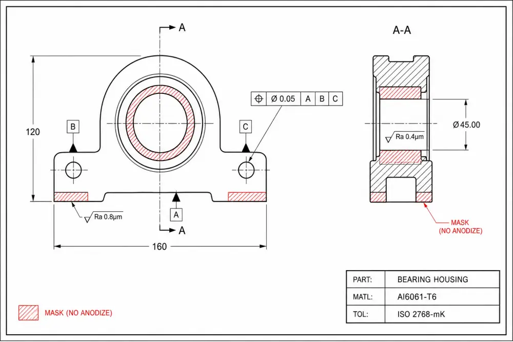
While modern CAM systems generate toolpaths directly from 3D CAD files, the CNC drawing checklist before manufacturing serves as the legal inspection contract. Every production drawing submitted for machining must satisfy standard CNC drawing requirements for manufacturing:
· Material Standard Callout: Specify exact alloy grade and temper condition per ASTM, ISO, or DIN standards (for example: Aluminum Alloy 6061-T651 per ASTM B209, not simply Aluminum).
· Linear and Geometric Tolerances: Complete title block with default general tolerance standards (ISO 2768-m or ASME Y14.5M) and explicitly dimensioned GD&T control frames for primary, secondary, and tertiary datums.
· Thread Specifications: Complete thread callouts including thread standard, nominal diameter, pitch, class of fit, and thread depth (for example: M6 x 1.0 - 6H, 12 mm min full thread, 15 mm drill depth).
· Surface Roughness Designations: Roughness average values assigned to explicit surfaces using standard ISO surface finish symbols.
· Surface Finishing and Coating Boundaries: Explicit callouts stating coating type (MIL-A-8625 Type II Class 2 Black, MIL-DTL-5541 Type II Class 1A Clear, or Electroless Nickel per AMS 2404). Clearly specify whether dimensions apply before or after plating.
· Critical Edge Conditions: Explicit notation distinguishing between functional sharp edges and non-contact handling edges.
2. 3D Model File Preparation Guidelines
To eliminate conversion errors during CAM ingestion:
· Export models in native Parasolid (.x_t), STEP AP242 (.step), or IGES (.igs) format. STEP AP242 is preferred as it supports embedded 3D Product and Manufacturing Information.
· Ensure the 3D model contains solid bodies only. Suppress or delete construction planes, surface patches, sketches, and disjointed reference bodies.
· Model all internal and external features at nominal dimensions. Do not export 3D geometry at upper or lower tolerance limits unless explicitly agreed upon with the supplier CAM team.
Factory-Level Engineering Collaboration with Dazao to Minimize Machining Costs
Precision machining performance relies on early engineering alignment. When mechanical engineers provide open visibility into functional context and assembly interfaces, Dazao application engineers propose design adjustments that protect product function while reducing cycle costs. Review our detailed aluminum CNC machining design guidelines for actionable geometric rules.
Our facility in Xiamen combines advanced 3-axis, 4-axis, and 5-axis simultaneous CNC milling with multi-spindle mill-turn centers. Operating under certified ISO9001:2015 and IATF16949:2016 quality management systems, our quality engineering team executes rigorous validation protocols:
· First Article Inspection Reports: Component validation per AS9102 standards, incorporating full balloon drawings and dimensional verification datasets.
· Comprehensive Metrology Verification: Multi-sensor Coordinate Measuring Machines (Zeiss CMM), optical video measuring systems, roundness testers, and surface roughness profilometers.
· Material and Chemical Traceability: Complete raw material mill test certificates, heat treatment charts, and third-party coating thickness inspection records.
Engaging with Dazao during the initial design phase allows your engineering team to identify geometric constraints, optimize raw material utilization, and eliminate unnecessary secondary setups before cutting raw stock.

FAQs
01.Why do taps break in blind holes when CAD thread depths match hole depths?
02.Why do H7 dowel holes fail pin-gage inspection after anodizing?
03.How does bulk material removal cause flat aluminum plates to warp?
04.Why do general 2D drawing edge break notes cause CAM gouging?
05.What is the primary cause of tool chatter in deep pocket milling?
06.How can designers eliminate secondary setups on 3-axis CNC mills?





