


Maximizing thread depth does not increase mechanical joint strength. Fastener clamping reliability depends on maintaining thread height between 65 percent and 75 percent, with effective engagement depth standardized at 1.0 to 1.5 times the bolt diameter for steels and 1.5 to 2.0 times the bolt diameter for aluminum alloys. Threading deeper than these practical thresholds increases tool breakage risks and machining costs without providing pullout strength benefits. Specifying correct pilot drill diameters, maintaining physical clearance in blind holes, and compensating for post-machining surface treatments prevent component scrap during final CNC machining stages.
Threaded Holes: The Scrap Bottleneck in Precision CNC Machining
In modern multi-axis CNC milling operations and high-precision CNC turning processes, internal threading is executed near the end of the manufacturing sequence. A complex prismatic part frequently undergoes extensive material removal, dynamic roughing, 5-axis contour surfacing, and tight-tolerance bore finishing prior to the tapping cycle. When an undersized pilot hole, insufficient bottom clearance, or metal chip packing causes a tap to shear off inside the workpiece, extracting the broken hardened tool without damaging the surrounding parent metal is extremely difficult. In many aerospace, medical, and semiconductor applications, a broken tap results in the immediate scrapping of an expensive component.
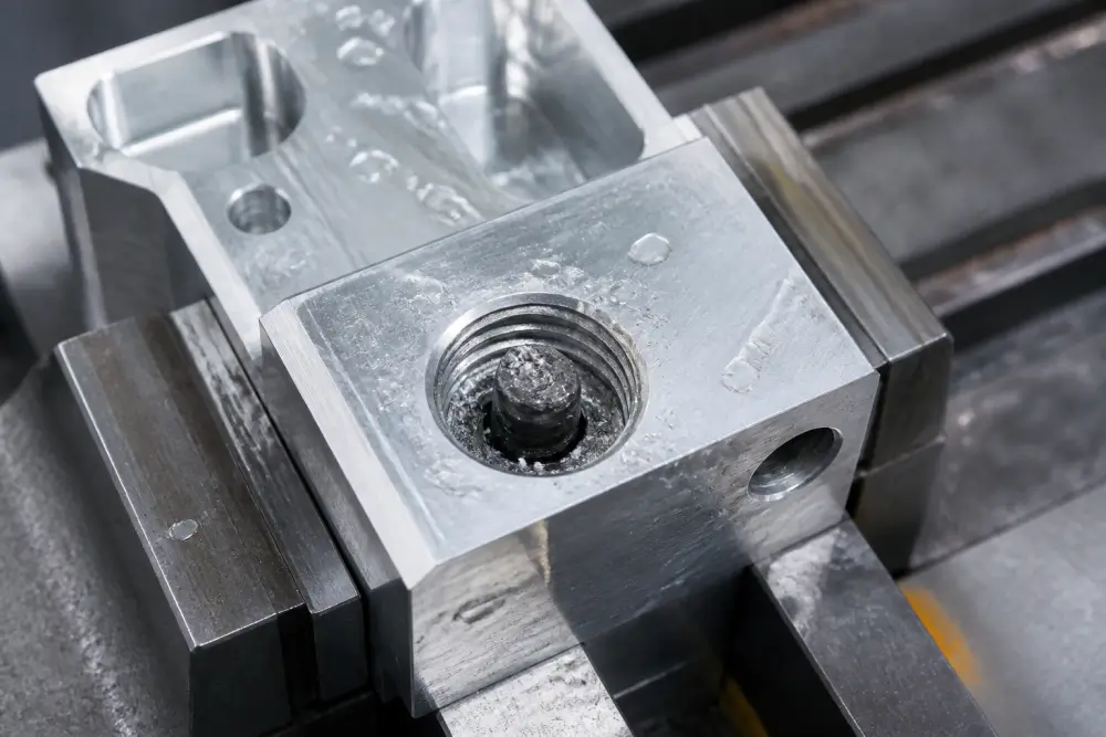
Threaded features are often treated as standard automated annotations in CAD software. However, reliable thread design cnc requires balancing parent material shear properties, dynamic cutting torque, tool geometry, and plating thickness allowances. Transitioning from standard practices for CNC hole design to internal thread generation involves a sharp increase in mechanical resistance. Machine shop audits across high-mix production lines at Dazao Machinery indicate that over 80 percent of thread-related manufacturing rejections stem from two primary engineering errors:
1. Specifying thread engagement depths far beyond the structural load transfer zone of the fastener assembly.
2. Failing to define adequate clearance between usable full-thread depth and total blind hole drill depth.
A well-engineered CNC tapped hole design does not maximize thread length. Instead, it balances fastener mechanical retention with practical cutting tool clearances and chip evacuation volume.
Thread Engagement Percentage and Tap Drill Size for CNC Threads
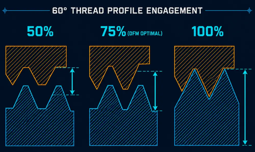
A frequent misconception in mechanical design is that an internal thread must provide 100 percent theoretical thread height, meaning complete crest-to-root contact, to achieve maximum assembly strength. In production CNC environments, targeting 100 percent thread engagement creates high machining risks, severe burr formation, and inflated cycle times.
Standard industrial practice balances thread profile height between 65 percent and 75 percent. Standard fasteners fail through bolt shank tensile fracture long before internal thread shear occurs when thread height remains within this target range. Increasing thread height from 70 percent to 100 percent yields less than a 5 percent increase in static pullout strength. However, that minor gain causes tapping torque to rise significantly, often exceeding the torsional shear limit of high-speed steel and solid carbide taps.
Cutting Taps vs. Forming Taps: Drill Size Divergence
Selecting the correct tap drill size for CNC threads depends on whether internal threads are cut by shearing metal chips or formed through plastic deformation.
· Cutting Taps (Spiral Point and Spiral Flute): These tools cut material away to generate internal geometry. They require a smaller pilot hole. They are recommended for cast iron, high-hardness alloy steels, plastics, and non-ductile alloys.
· Forming Taps (Cold Forming or Roll Taps): These tools displace metal plastically without producing chips. They produce higher fatigue strength along the thread profile and eliminate chip evacuation problems in blind holes. However, forming taps require a larger pilot drill and are only suitable for ductile materials with elongation ratings above 10 percent, such as Al6061-T6, Al7075-O, copper alloys, austenitic stainless steels, and low-carbon steels.
|
Nominal Thread Size |
Pitch (mm) / TPI |
Cutting Tap Drill Size (mm / Inch) |
Engagement % (Cutting) |
Forming Tap Drill Size (mm / Inch) |
Engagement % (Forming) |
|
M3 x 0.5 |
0.50 mm |
2.50 mm (0.0984 in) |
69% |
2.80 mm (0.1102 in) |
68% |
|
M4 x 0.7 |
0.70 mm |
3.30 mm (0.1299 in) |
68% |
3.70 mm (0.1457 in) |
65% |
|
M5 x 0.8 |
0.80 mm |
4.20 mm (0.1654 in) |
69% |
4.65 mm (0.1831 in) |
66% |
|
M6 x 1.0 |
1.00 mm |
5.00 mm (0.1969 in) |
69% |
5.55 mm (0.2185 in) |
67% |
|
M8 x 1.25 |
1.25 mm |
6.80 mm (0.2677 in) |
67% |
7.40 mm (0.2913 in) |
68% |
|
M10 x 1.5 |
1.50 mm |
8.50 mm (0.3346 in) |
68% |
9.30 mm (0.3661 in) |
67% |
|
1/4-20 UNC |
20 TPI |
5.10 mm (0.2010 in) |
75% |
5.80 mm (0.2280 in) |
65% |
|
5/16-18 UNC |
18 TPI |
6.60 mm (0.2570 in) |
77% |
7.30 mm (0.2900 in) |
65% |
|
3/8-16 UNC |
16 TPI |
8.00 mm (0.3125 in) |
72% |
8.80 mm (0.3480 in) |
67% |
|
1/2-13 UNC |
13 TPI |
10.80 mm (0.4219 in) |
75% |
11.80 mm (0.4687 in) |
67% |
Thin-Wall Bulging Risks with Roll Forming Taps
Although roll forming taps eliminate chip clearing issues, they generate high outward radial displacement forces in the parent material. When an internal thread is formed close to an external edge or within a thin housing that violates minimum CNC wall thickness guidelines, this radial pressure pushes the ductile metal outward.

At Dazao Machinery, precision coordinate measuring machine inspections on thin-walled sensor enclosures revealed micro-bulges ranging from 0.025 mm to 0.060 mm on ground datum faces adjacent to M4 roll-tapped holes. This outward plastic displacement caused the parts to fail outer envelope geometric tolerances. When designing internal threads near walls thinner than 1.5 times the nominal thread diameter, specify cutting taps or CNC thread milling instead of forming taps, or select a slightly larger pilot hole to relieve displacement stress.
CNC Thread Engagement Depth: The Law of Diminishing Returns
Specifying full-thread depths of three or four times the nominal diameter under the assumption that deeper threads create stronger structural joints is an engineering error. Structural load distribution and elastic deformation dynamics show that internal threads provide diminishing returns beyond specific depth thresholds.
Load Distribution Mechanics Across Engaged Threads
When a threaded fastener is torqued into an internal thread, the axial clamping load is distributed unevenly across engaged pitches due to differential pitch strain:
· The first thread pitch absorbs approximately 38 percent to 40 percent of the total axial load.
· The second thread pitch absorbs approximately 22 percent to 25 percent of the remaining load.
· The third thread pitch absorbs approximately 15 percent to 18 percent of the load.
· The fourth, fifth, and sixth thread pitches combine to carry less than 15 percent of the load.
· Any thread pitch beyond the sixth carries negligible static or dynamic tensile load.
Extending thread depth beyond mechanical requirements does not increase joint strength, but it significantly elevates manufacturing hazards.
Engagement Depth Guidelines by Material Class
To determine practical CNC thread engagement depth, the shear strength of the internal parent material must match the tensile proof strength of the fastener. In-depth technical publications such as our engineering guide to aluminum CNC machining emphasize aligning thread depth with parent metal mechanical properties:
|
Parent Material Group |
Examples |
Recommended Engagement Depth |
Design Rationale & Mechanical Limiting Factor |
|
High-Strength Steels |
4140, 4340, Hardox |
1.0 x Nominal Diameter (1.0D) |
Parent metal shear strength matches or exceeds Class 10.9 and 12.9 bolt tensile strength. |
|
Stainless Steels |
304, 316L, 17-4PH |
1.2 x to 1.5 x Nominal Diameter |
Prevents galling while providing balanced load transfer under high assembly torque. |
|
Medium Alloys & Cast Iron |
Ductile Iron, Brass, Bronze |
1.5 x Nominal Diameter (1.5D) |
Moderate shear area compensates for lower matrix tensile and yield properties. |
|
Structural Aluminum Alloys |
Al6061-T6, Al7075-T6 |
1.5 x to 2.0 x Nominal Diameter |
Target thread engagement for aluminum; balances shear strength against Class 8.8 bolts. |
|
Engineering Plastics |
PEEK, POM (Acetal), Nylon |
2.0 x to 2.5 x Nominal Diameter |
Large shear area compensates for low creep resistance and low elastic modulus. |
Applying established DFM principles for aluminum CNC machining ensures internal threads provide full joint integrity without unnecessary depth.
Micro-Chip Packing in Deep Blind Holes
Specifying CNC blind hole thread depth greater than 2.5 times the nominal diameter introduces severe machining risks. When a spiral flute tap operates deeper than 2.5 times its diameter, high-pressure machine coolant cannot easily reach the active cutting zone at the bottom of the cavity.
In ductile alloys like Al6061-T6 and 316L stainless steel, long chips pack into the bottom clearances and recut along the thread flanks. This creates micro-tearing on the load-bearing 60-degree tooth surfaces. Although the hole may pass a standard manual Go-gauge inspection, these micro-tears act as stress concentration points under dynamic fatigue loading, reducing service life by over 30 percent. In production, this chip packing causes sudden tap binding and tool breakage.
Geometric Separation: Thread Depth vs Drill Depth in Blind Holes
Designing a blind threaded hole requires maintaining a clear geometric distinction between usable full-thread depth and total drilled pilot hole depth. Automated CAD presets often position the pilot drill bottom only one or two pitches deeper than the thread callout. On a CNC machining center, this lack of clearance leads directly to tap collisions, chip compaction, and stripped entry threads. Understanding thread depth vs drill depth avoids these manufacturing issues.

Practical Clearances in Blind Holes
Standard taps cannot generate full-profile threads to the extreme tip of the tool because forward cutting teeth feature a chamfer lead:
· Taper Taps: Feature seven to ten pitches of lead chamfer. Used for manual starting or tough alloy steels.
· Plug Taps: Feature three to five pitches of lead chamfer. Standard for through holes and deep blind holes.
· Bottoming Taps: Feature one to two pitches of lead chamfer. Required when full threads must reach near the bottom of a blind hole.
To prevent tap tip collision with the conical drill point and ensure adequate space for chips, machinists maintain a buffer zone. A practical rule of thumb is to add at least four thread pitches of depth below the usable thread, plus standard allowance for the conical drill point tip.
For example, an M6 hole with a 1.0 mm pitch requiring 12.0 mm of full thread is typically drilled to a total depth of 17.0 mm. Requiring full threads close to the bottom of a shallow drilled cavity leads to secondary manual bottom-tapping operations, significantly increasing aluminum CNC machining cost drivers.
Hole Entrance Countersinks and Deburring
A threaded hole without an entrance chamfer creates assembly defects. As the tap cuts the initial pitch, axial cutting forces pull unsupported parent metal upward, creating a raised burr around the perimeter of the hole. This raised metal prevents mating components from sitting completely flush on the datum face.
Standard CNC thread design guidelines recommend a 90-degree to 120-degree chamfer at the hole entrance. The chamfer outer diameter should measure slightly larger than the nominal thread diameter, typically about ten percent wider. This keeps the first thread pitch below the mounting face and eliminates secondary manual deburring.
Plating Thickness and Pitch Diameter Shrinkage
A major design issue occurs when standard thread tolerances are specified on components that receive surface treatments, such as Type II or Type III (Hardcoat) anodizing, electroless nickel plating, or electro-galvanic coatings.
Because internal threads have angled 60-degree tooth flanks, coating applied to the surface accumulates on both sides of each tooth. In practice, this creates a dimensional reduction on the internal pitch diameter equal to roughly four times the single-surface coating thickness.

If an aluminum part calls for a standard M4 internal thread followed by a 25 micrometer (0.0010 inch) hard anodize layer, the coating build-up reduces internal pitch diameter clearance by approximately 100 micrometers. Because this reduction consumes the entire standard tolerance band, the finished part will fail thread gauge inspection and cause fasteners to seize during assembly.
Maintaining correct aluminum CNC machining tolerances on coated parts requires using oversize taps (such as 6G or 7G classes) or adjusting thread mill radial tool offsets during machining. Technical drawings should clearly state that thread tolerance applies after surface coating, indicating oversize machining requirements before plating.
CNC Thread Milling vs Tapping vs Threaded Inserts
Evaluating CNC thread milling vs tapping and threaded inserts depends on hole diameter, production volume, material machinability, and required service cycles.
|
Engineering Factor |
Rigid CNC Tapping |
CNC Thread Milling |
Threaded Wire Inserts (Helicoil / Keensert) |
|
Cycle Time |
Fast (1 to 3 seconds per hole). |
Moderate (5 to 15 seconds per hole). |
Slow (requires drilling, tapping, manual insertion, tang break). |
|
Tool Breakage Risk |
High in tough alloys or deep blind holes; tap extraction is difficult. |
Near-Zero; broken cutters do not lock into the workpiece and are easily removed. |
Very Low during machining of the insert pilot hole. |
|
Tolerance Adjustability |
Fixed by tool geometry; zero machine-side diameter adjustability. |
Fully dynamic; pitch diameter adjustable via CNC tool radius compensation. |
Fixed by specialized tap geometry. |
|
Blind Hole Bottom Clearance |
Requires three to four pitches of bottom clearance cavity. |
Can machine full threads within one pitch of a flat blind bottom. |
Requires deep engagement to house insert length plus engagement depth. |
|
Material Applicability |
Excellent for production runs in structural steels, brass, and aluminum. |
Preferred for hardened steels (>45 HRC), Ti-6Al-4V, Inconel, and large bores (>M12). |
Mandatory for soft parent alloys (Al6061, Magnesium) with high-cycle bolt removal. |
|
Unit Tooling Cost |
Low to moderate. |
Higher initial tool cost, but one tool handles multiple hole diameters of identical pitch. |
Low tooling cost, but adds recurring component insert hardware costs. |
When to Specify CNC Thread Milling
Thread milling is preferred over standard tapping when:
1. Hole diameter exceeds M12 (0.500 inch), where tapping torque approaches spindle torque limits.
2. The parent material is difficult to machine, such as Titanium Grade 5, Inconel 718, or pre-hardened tool steels above 45 HRC.
3. Full threads must reach near the bottom of a shallow blind hole, leaving under 1.5 pitches of bottom clearance.
4. Managing toolpath radii to balance CNC corner radius design and machining cost on complex part features.

When to Specify Wire Thread Inserts
Direct tapping into light alloys (Al6061-T6, Al7075, AZ91D magnesium) is not recommended for parts subject to frequent maintenance disassembly. Torquing steel bolts repeatedly into aluminum threads causes friction galling and strips internal threads over time. Specifying tapped holes for Helicoil or Keensert inserts distributes tensile loads over a larger diameter in the parent metal, creating a durable stainless steel interface.
Thread Standards, Selection, and 2D/3D Drawing Callouts
Understanding UNC vs UNF vs metric threads CNC helps optimize assembly efficiency and mechanical joint integrity:
· Metric Coarse (ISO 261 / 68-1): The global standard. Provides balanced assembly speed, predictable torque-tension relationships, and balanced resistance to cross-threading.
· UNC (Unified National Coarse): Features deeper thread profiles with a larger pitch. Recommended for lower-strength cast materials, aluminum, and general structural assemblies where rapid assembly and high resistance to thread stripping are required.
· UNF (Unified National Fine): Features a smaller pitch and shallower thread depth, providing a larger tensile stress area on the mating bolt shank. Delivers higher vibration resistance and finer adjustment resolution in automotive linkages and aerospace instrumentation. However, UNF threads are more susceptible to cross-threading and seize rapidly in contaminated or galling environments.

Standard 2D Engineering Drawing Callouts
Ambiguous drawing callouts cause programming delays and engineering change orders. A complete CNC threaded hole callout must define thread profile, pitch, class of fit, usable depth, drill depth, and post-processing requirements.
Standard Metric Callout Format:
M8 x 1.25 - 6H - THD 16.0 MIN FULL THD - DRILL 21.0 MAX
Nominal Metric Major Diameter: 8 mm
Thread Pitch: 1.25 mm
Tolerance Class: 6H Internal Fit
Minimum Usable Full Thread Depth: 16.0 mm
Maximum Allowed Pilot Drill Depth: 21.0 mm
Standard Unified Callout Format:
1/4-20 UNC - 2B - THD .500 MIN - DRILL .688 MAX
CAD Modeling Guidelines: Avoiding Physical Swept Threads
Do not model physically swept 3D helical spiral geometry in CAD files submitted for CNC manufacturing. Physical thread sweeps generate dense surface meshes that inflate STEP and Parasolid file sizes from megabytes to gigabytes. This can crash CAM software, corrupt feature-recognition algorithms, and misalign toolpaths. Model threaded features as simple cylindrical holes matching the nominal tap drill diameter or major diameter, and represent thread specifications using cosmetic thread metadata and linked 2D PDF technical drawings.
Machine Shop Root-Cause Analysis: Case Studies from Dazao Machinery
Case Study 1: M2 Micro-Hole Tap Breakage in Medical Al6061-T6 Housings
· Component: Optical Sensor Baseplate for Endoscopic Surgery.
· Failure Incident: The customer drawing specified 24 blind holes with an M2 x 0.4 - 6H callout. Usable thread depth was marked at 5.0 mm, with a maximum allowable pilot drill depth of 5.8 mm (leaving 0.8 mm bottom clearance, equal to two thread pitches). Rigid tapping using high-speed steel spiral flute taps resulted in a 22 percent tap breakage rate across the first production batch.

· Root Cause Analysis: At a depth of 5.0 mm (2.5 times the tool diameter), high-pressure coolant failed to displace compacting aluminum micro-chips out of the narrow flute channels. The chips backed up within the tight bottom clearance, causing chip packing that jammed the tap tip upon spindle reversal.
· Corrective Action: Engineers at Dazao Machinery worked with the client to adjust allowable pilot drill depth to 6.8 mm, providing ample chip accumulation space. The process was also transitioned to a single-form solid carbide micro-thread milling cutter rotating at 18,000 RPM with high-pressure air blast. Tap breakage dropped to zero and part scrap was eliminated.
Case Study 2: Fastener Galling on 316L Stainless High-Pressure Flanges
· Component: Marine Subsea Valve Body Flange.
· Failure Incident: During final assembly, Class A4-80 stainless steel bolts torqued into M10 x 1.5 blind holes seized and sheared off at only 65 percent of the target 45 N·m assembly torque.
· Root Cause Analysis: Inspection revealed two manufacturing oversights:
1. The drawing omitted entrance countersinks. The lead thread rolled upward during tapping, creating an interference burr that pinched the fastener under the bolt head.
2. The tap drill was sized at 8.40 mm, producing an overly tight 78 percent thread engagement. In austenitic 316L stainless steel, this tight engagement generated extreme friction, causing passive chromium oxide breakdown and cold-weld galling under load.
· Corrective Action: The tap drill size was increased to 8.60 mm, reducing thread engagement to 63 percent while maintaining structural pullout strength. A 90-degree entrance countersink was added, and a molybdenum disulfide anti-seize assembly protocol was implemented, eliminating fastener galling across subsequent lots.
DFM Quick-Checklist for CNC Thread Design
Before releasing engineering drawings to production, verify internal thread specifications against this DFM checklist:
Engagement Depth Check: Is thread depth limited to 1.0 to 1.5 times bolt diameter for steel, or 1.5 to 2.0 times bolt diameter for aluminum?
Blind Hole Clearance: Is the total drill depth at least four pitches deeper than the required usable thread, plus drill point allowance?
Entrance Chamfer: Is a 90-degree to 120-degree countersink specified with an outer diameter slightly larger than the major diameter?
Plating Allowance: If hard anodize or electroless nickel is required, are oversize pre-plate tolerances explicitly defined?
Thin-Wall Proximity: Are threaded features near thin exterior walls set to use cutting taps or thread milling instead of roll forming?
Standard Tooling Sizing: Are thread callouts matched to standard off-the-shelf metric or UN pitches to avoid custom tooling costs?
3D CAD Cleanliness: Are CAD models free of physically swept helical threads, using cosmetic metadata and linked 2D PDF drawings instead?

FAQs
01.How do you calculate thread depth vs drill depth for CNC blind holes?
02.What is the optimal thread engagement depth for aluminum 6061-T6?
03.Why do taps break in stainless steel blind holes during CNC tapping?
04.When should engineers choose thread milling over rigid tapping?
05.How does hard anodizing affect internal thread pitch diameter tolerances?
06.What is the difference between UNC and UNF threads in CNC machining?





