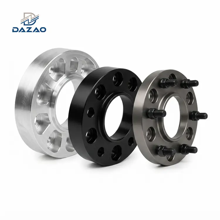
5-Axis Machined Aluminium Racing Wheel Spacers
Billet 7075-T6 Hubcentric Track and Off-Road Flanges Engineered for Zero High-Speed Vibration
Core Engineering Bullet Points:
Single-setup 5-axis indexing eliminates runout; hub concentricity ≤0.02mm.
True flat mounting surface maintains face runout ≤0.01mm at 120km/h+.
Forged 7075-T6 bar stock delivers 570 MPa tensile strength.
Class 12.9 metric wheel studs installed via displacement-controlled press.
Load-graded CNC pocketing verified by static and dynamic FEA.
Zero tooling cost; prototypes ready for dispatch in 3 business days.
100% CMM verification of pitch circle diameters and center-bore steps.

Billet Wheel Spacer Engineering Capabilities and Manufacturing Infrastructure
Single-Setup Multi-Axis Machining Ensuring Total Coaxial Alignment and Dynamic Balance
We produce 5-Axis Machined Aluminium Racing Wheel Spacers engineered for competitive motorsport, desert off-road racing, and heavy commercial pickup platforms. We produce these safety-critical chassis components from solid billets of certified forged 7075-T6 and 6061-T6 aluminum using multi-axis turn-milling and 5-axis continuous milling centers.
By executing all operations-including back-face turning, center-bore profiling, weight-reduction pocketing, and PCD drilling-in a single clamping setup, our process eliminates the concentricity errors common in conventional 3-axis two-step setups. Each batch is paired with Class 12.9 cold-forged studs pressed using closed-loop servo monitoring to prevent thread galling, runout-induced vibration, and wheel-separation failures under dynamic cornering loads. Explore our full range of precision 5-axis CNC machining services for custom chassis projects.

Technical Field Failure Analysis and Structural Root-Cause Countermeasures
Lessons from Real-World Track and Desert Dynamic Testing Transformed into Production Standards
Chassis components must withstand high torque, lateral shear, and severe impact. Below is a review of three standard industry failure modes and our engineering countermeasures implemented across all production lines.
High-Speed Steering Shake via Dual-Setup Runout Stack-up
· Root-Cause Analysis: Standard 3-axis machining requires flipping the workpiece to finish the hubcentric centering lip and mounting face. Part repositioning errors stack up, resulting in radial runout exceeding 0.08mm relative to the hub bore. At vehicle speeds above 120 km/h, this eccentricity generates dynamic imbalance that cannot be resolved through standard wheel balancing.
· Manufacturing Countermeasure: We migrated all production to 5-axis multi-tasking centers. The hub bore, outer diameter, centering register, and lug pattern are cut in a single clamping cycle. Concentricity is held to ≤0.02mm, and lateral runout is restricted to ≤0.01mm across the entire mounting face.
Structural Fatigue Cracking from Dynamic Shock Loads
· Root-Cause Analysis: Generic pocketing designs with sharp 90° internal corners introduce stress concentration nodes. Under vertical landing impacts during desert off-road testing, shock loads can exceed three times the static axle load, initiating micro-fractures at the base of the pockets.
· Manufacturing Countermeasure: We separate component engineering by operational duty cycle. Track components utilize multi-angle pocketing optimized for unsprung weight reduction. Off-road and truck variants use R3.0 continuous corner fillets, 2.0mm thicker wall sections, and continuous outer perimeter ribs. All revised geometries pass 3x static rated load FEA simulation prior to chip removal.
Stud Thread Stripping and Press-Fit Axis Deviation
· Root-Cause Analysis: Standard manual hydraulic presses apply uncontrolled downward force without displacement verification. Over-pressing induces internal broaching failure, while under-pressing results in angled studs (perpendicularity deviations >0.10mm) and uneven thread engagement.
· Manufacturing Countermeasure: We press-fit all Class 12.9 hardware using automated servo presses equipped with integrated force-displacement sensors. The system halts and rejects any component deviating from preset insertion parameters. Finished assemblies undergo 100% CMM inspection for stud perpendicularity (≤0.03mm) and axial protrusion height (±0.10mm).

Technical Architecture Benchmark: 5-Axis Forged 7075-T6 vs Conventional Spacers
Direct Data Comparison Highlighting Dimensional Integrity, Mechanical Rigidity, and Safety Margins
|
Technical Metric |
5-Axis Forged 7075-T6 Spacers |
Conventional 3-Axis Cast Aluminum |
Generic Mild Steel Spacers |
|
Machining Process |
Single-setup continuous 5-axis |
Dual-setup 3-axis vertical CNC |
Multi-operation manual lathe |
|
Hubcentric Concentricity |
≤ 0.020 mm |
0.080 mm – 0.150 mm |
0.050 mm – 0.100 mm |
|
Mounting Face Flatness |
≤ 0.010 mm |
0.040 mm – 0.080 mm |
0.030 mm – 0.060 mm |
|
Yield Strength |
505 MPa |
160 – 220 MPa |
250 – 350 MPa |
|
Material Density |
2.81 g/cm³ (Low inertia) |
2.70 g/cm³ (Porosity risks) |
7.85 g/cm³ (High mass) |
|
Stud Retention Standard |
Servo-press displacement verified |
Standard manual arbor press |
Loose through-holes / press |
|
Tooling & Setup Charge |
Zero (Direct CAD-to-CNC) |
Tooling/Die cost ($2,500+) |
Low tooling, high setup time |
Our facility also supplies high-strength 7075-T6 aluminum CNC parts for suspension uprights and caliper brackets.

Mechanical Specifications and Dimensional Tolerances Matrix
Comprehensive Physical, Geometric, and Hardware Parameters for Engineering Verification
|
Parameter Dimension |
Engineering Specification Range |
|
Raw Material Grades |
Forged Al7075-T6, Al6061-T6, Al6082-T6 (EN 10204 3.1 Certified) |
|
Bolt Patterns (PCD) |
4-Lug, 5-Lug, 6-Lug, 8-Lug (e.g., 4x100, 5x114.3, 5x120, 6x139.7, Custom PCDs) |
|
Thickness Range |
5.0 mm to 75.0 mm (Custom stepped sizes available upon request) |
|
Center Bore Range |
Ø54.1 mm to Ø110.0 mm with precision-turned hubcentric lip |
|
Dimensional Tolerances |
Bore/Pilot: ±0.005 mm; PCD Center: ±0.010 mm; Thickness: ±0.025 mm |
|
Geometric Tolerances |
Concentricity: ≤0.020 mm; True Perpendicularity: ≤0.015 mm |
|
Stud Specifications |
Class 12.9 High-Tensile Steel, M12x1.25, M12x1.5, M14x1.5, 1/2"-20, Dacromet/Zinc |
|
Surface Treatments |
Type II Anodized (Color), MIL-A-8625 hardcoat anodizing services, Micro-bead Blast |
|
Pre-Anodize Tolerance Offset |
Precision-compensated bore pre-machining (+0.015 mm) for plating thickness |
|
Production Lead Times |
Prototypes: 3–4 Days; Batch (500–2,000 pcs): 8–12 Days |

Duty-Graded Material and Structural Configuration Selector
Selecting the Exact Alloy and Web Geometry for Track, Trail, and Heavy Hauling
· 6061-T6 Billet: Suitable for street widening, bolt-on aesthetic stance correction, and occasional light track-day use. Yields clean bright-dip color anodizing with balanced production economics.
· 7075-T6 Forged Aluminum: Standard selection for high-downforce GT racing, drifting, rock crawling, and heavy truck track widening. Delivers twice the fatigue limit of 6061-T6 to handle hard curb strikes and rut impacts.
· Hubcentric Step Designs: Integrated hub-locating lips transfer vehicle weight and shear loads directly into the axle snout, preventing wheel studs from taking radial shear loads.

Metrology Verification and Quality Assurance Protocol
Full Traceability from Spectrometry Inspection to CMM Geometric Validation
1. Incoming Material Verification: Optical emission spectrometry validates aluminum alloy chemistry. Eddy-current testers reject bar stock showing internal voids or inclusions.
2. First Article Inspection (FAI): Zeiss multi-sensor Coordinate Measuring Machines (CMM) inspect the initial piece from each machine setup to create complete AS9102-compliant dimensional reports.
3. In-Process Runout Testing: 100% of manufactured spacers are mounted onto precision test fixtures to verify runout and face wobble using dial indicators (target: total indicated runout <0.02mm).
4. Post-Surface Treatment Checks: Thread plug gages (6H class) and bore micrometers verify critical hub locating steps after hard anodizing to prevent fitment interference.

Specialized Automotive and Motorsport Application Sectors
Chassis Widening and PCD Conversion Solutions for Demanding Vehicle Platforms

Time Attack & Circuit Racing
High-performance hubcentric spacers minimizing rotating unsprung mass on high-downforce track cars.

Off-Road Trophy Trucks & Rock Crawlers
Structural off road wide track wheel spacers built to handle suspension bottoming and high-impact drop loads.

Heavy-Duty Commercial Pickups
Heavy duty forged wheel spacers for trucks to correct wheel offset on dual-rear-wheel axles and lifted chassis.

Custom PCD Transversions & Restomods
Custom PCD adapter wheel spacers CNC machined to match modern multi-piston brake systems with non-native hub patterns, fitting alongside CNC machined automotive suspension components.
FAQs

01.Do wheel spacers inherently cause wheel bearing failure?
02.Why do some wheel spacers vibrate violently at highway speeds?
03.Is 7075-T6 aluminum strictly necessary over 6061-T6?
04.How do you prevent wheel studs from loosening or pulling out?
05.What minimum thread engagement is required when running slip-on spacers?
06.Will hardcoat anodizing alter the critical hub-fit tolerances?
Submit Your CAD Drawings for Engineering DFM Feedback
Upload your 2D drawings and 3D CAD files (STEP, IGES, Parasolid, DXF, or DWG) to receive a DFM manufacturing evaluation, stress-distribution check, and formal production quote within 24 hours.
Contact Us

Hot Tags: 5-Axis Machined Aluminium Racing Wheel Spacers,hubcentric wheel spacers 7075 T6 aluminum,racing wheel spacers with 12.9 grade studs,custom 5 axis CNC wheel spacers,custom PCD adapter wheel spacers CNC machined