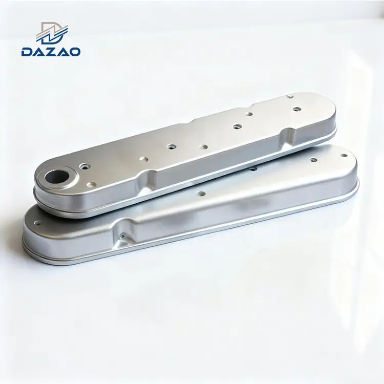
CNC Machined Billet Aluminum Valve Covers Precision Engine Components
Engineered from monolithic billet stock to eliminate thermal warping, structural porosity, and gasket oil leaks under high-stress conditions.
Core Engineering Features:
100% solid 6061-T6/7075-T6 aluminum billet construction.
Mating surface flatness ≤0.02mm prevents oil leakage.
Helicoil stainless steel inserts prevent thread stripping.
Custom CNC machined valve covers with 7-day lead time.
Black anodized billet aluminum valve covers, laser etched.
Zero-void CNC machining high performance racing parts.

Engineered Capabilities and Billet Machining Architecture
Zero-void aluminum billet milling engineered for extreme thermal stability and dimensional precision.
High-precision CNC machining billet aluminum valve cover assemblies are engineered for demanding automotive applications, race engines, and aftermarket performance upgrades. Machined entirely from solid 6061-T6 or 7075-T6 aerospace aluminum billet blocks using multi-axis milling, these covers eliminate the structural cracking, oil seepage, and porosity failure modes associated with OEM cast aluminum or plastic valve covers.
Each valve cover undergoes a dedicated stress-relief thermal cycle prior to final machining to guarantee long-term thermal stability. Mating surfaces are precision-ground to achieve a flatness tolerance within ≤0.02 mm, preventing warping under extreme cylinder head temperatures up to 120°C. We support low-to-high volume production, short-run prototyping, and private-label production with custom spark plug well dimensions, integrated oil baffle systems, and breather configurations utilizing our specialized 5-axis CNC machining services.

Technical Specifications and Engineering Benchmarks
Comprehensive material, tolerance, and surface finish metrics for high-performance engine applications.
All technical dimensions and material standards for our aluminum CNC machining parts are verified through rigorous measurement protocols:
|
Engineering Dimension |
Technical Specification / Standard Parameter |
Inspection Method / Standard |
|
Primary Material Grades |
AL 6061-T6, AL 7075-T6 |
Material Test Report (MTR) per batch |
|
Manufacturing Process |
3-Axis & 5-Axis Monolithic CNC Milling |
Continuous 5-Axis machining |
|
Max Machining Envelope |
800 mm x 550 mm x 300 mm |
Optical 3D Scanning |
|
Mating Surface Flatness |
≤ 0.02 mm (Post-thermal stabilization) |
CMM & Dial Indicator Grid |
|
Dimensional Tolerance |
Machining: ±0.025 mm | Features: ±0.010 mm |
CMM / Pin Gauges |
|
Surface Finish Roughness |
Ra 0.8 µm to Ra 1.6 µm (As-machined/Bead Blasted) |
Profilometer |
|
Thread Protection |
Helicoil Stainless Steel Inserts (1.5D / 2D) |
Thread Go/No-Go Plug Gauges |
|
Surface Treatments |
Type II Anodizing, Type III Hardcoat, Bead Blast |
Thickness Gauge (≥ 20 µm) |
|
Branding Options |
Precision Fiber Laser Engraving, CNC Relief |
Optical Comparator |
|
Prototyping Lead Time |
7 Working Days |
First Article Inspection (FAI) |
|
Batch Production Time |
10–15 Working Days |
Sampling per AQL 1.0 |

Real-World Case Studies and Engineering Failure Analysis
Root-cause analyses and corrective protocols derived from actual track testing and client field reports.
Thermal Warping & Oil Seepage on V8 Muscle Car Covers
· Failure Mode: Early production runs of V8 aluminum valve covers machined to standard room-temperature tolerances (0.05 mm flatness) experienced edge warping and oil seepage after prolonged track operation at engine temperatures exceeding 100°C.
· Root Cause Analysis: Residual internal stresses in extruded aluminum billet released during high-temperature engine operating cycles, causing mechanical distortion across large surface spans.
· Engineered Solution: Implemented a two-stage thermal stabilization process. Rough machining is followed by sub-zero and thermal stress-relief aging before final precision milling. Mating surfaces undergo mirror grinding to maintain flatness within ≤0.02 mm. Every new structure undergoes a 10-cycle thermal shock test (-20°C to 120°C); thermal distortion must register ≤0.01 mm to pass validation.
Ignition Coil Pack Bore Misalignment in JDM Engines
· Failure Mode: CNC valve covers produced according to original OEM CAD drawings resulted in clearance issues on 30% of aftermarket high-output ignition coils during assembly, causing incomplete seating and cylinder misfires.
· Root Cause Analysis: Factory OEM drawings do not account for dimensional variances found in secondary aftermarket performance coils.
· Engineered Solution: Created a physical fitment database covering mainstream OEM and aftermarket ignition coils. Total tolerance stack-up is redistributed across coil mounting bores and sealing channels. Every first article is physically test-fitted with target coil packs using plug-and-pull force gauges, ensuring 99%+ assembly success rates without manual adjustments.
Thread Stripping under High-Frequency Maintenance
· Failure Mode: Track-spec anodized aluminum valve covers subjected to frequent removal during race weekend inspections experienced stripped aluminum threads after 3–5 maintenance cycles.
· Root Cause Analysis: Chemical anodizing salts altered internal thread pitch tolerances, and raw aluminum threads lack the shear strength for high-frequency torquing.
· Engineered Solution: Standardized thread protection options:
1. Street Applications: Thread bores are masked with silicone plugs before anodizing and re-tapped post-coating to ensure smooth fastener engagement.
2. Race & Track Applications: High-stress thread holes are pre-fitted with precision thread machining capabilities, extending thread fatigue life beyond 50 assembly cycles under high torque.

Proprietary Quality Standards and Process Differentiators
Advanced manufacturing controls that guarantee structural integrity and precise component fitment.
Thermal Stability Management
Unlike standard machine shops that only record room-temperature tolerances, our facility controls high-temperature structural stability. By integrating stress-relief thermal processing into the CNC workflow, internal stress vectors are neutralized. Mating surfaces remain flat under sustained high thermal loads, preventing oil leaks over years of operation.
Ignition Coil Clearance Matrix
We do not rely solely on nominal drawing dimensions. Our engineering team matches coil pocket geometry to real-world ignition coil profiles. Precision clearance tolerances prevent rubber boot pinching, guarantee solid electrical contact, and eliminate moisture ingress into the spark plug wells.
Thread Protection Standards
Raw aluminum threads degrade quickly when exposed to frequent servicing. We mitigate thread galling and stripping by deploying process-specific solutions: protective masking for standard commercial parts and factory-installed Helicoil inserts for heavy-duty motorsport applications.

Engineered Billet Aluminum vs Standard Cast and OEM Plastic Covers
A side-by-side performance comparison highlighting structural durability and fatigue resistance.
|
Operational Metric |
CNC Billet Aluminum Cover |
Die-Cast Aluminum Cover |
OEM Molded Plastic Cover |
|
Material Integrity |
Solid 100% void-free billet stock |
Risk of internal porosity/sand holes |
High risk of thermal fatigue cracking |
|
Mating Surface Flatness |
≤ 0.02 mm (Precision ground) |
0.08 mm – 0.15 mm |
Warps over time due to engine heat |
|
Oil Leakage Risk |
Zero (Thermal shock verified) |
Moderate (Porosity seepage risk) |
High (Post 50,000 miles aging) |
|
Customization Flexibility |
No tooling needed; instant revision |
High tooling cost ($10,000+) |
Extremely high tooling cost |
|
Thread Fatigue Resistance |
High (Helicoil insert options) |
Low (Threads strip in soft cast aluminum) |
Poor (Brass inserts pull out of plastic) |
|
Aesthetic Customization |
Multi-color anodizing, laser engraving |
Rough surface paint/powder coat |
Plain textured black plastic |

Material Selection and Engine Application Guide
Selecting the optimal alloy and surface treatment for street, track, and private-label requirements.
Material Performance Breakdown
AL 6061-T6
· Characteristics: High strength-to-weight ratio, excellent corrosion resistance, uniform anodizing acceptance.
· Recommended Application: Street performance builds, daily driven vehicles, show cars, and standard aftermarket replacement lines.
· Consideration: Yield strength is lower than 7075; not recommended for extreme high-vibration off-road racing frames.
AL 7075-T6
· Characteristics: Zinc-alloyed aerospace aluminum, extreme tensile strength (570 MPa), high fatigue resistance.
· Recommended Application: Professional motorsport series, endurance racing, boosted race engines experiencing severe vibration. Learn more about our specialized 7075-T6 aluminum machining options.
· Consideration: Higher raw material cost; lighter color variation may occur during light-tint anodizing (Type III hardcoat recommended).
Application Profile Matching
· Street Performance: Select 6061-T6 with Type II Anodizing and Standard Masked Thread Protection. Best cost-to-performance ratio.
· Motorsport / Racing: Select 7075-T6 with Type III Hardcoat Anodizing and Factory Helicoil Inserts. Built for maximum thermal cycling and high-frequency maintenance.
· Private Label Brands: Select 6061-T6 with Laser Etched Logos, Custom Anodizing Color Matching, and Retail Box Packaging.

Comprehensive Quality Control and Inspection Protocols
Six-tier verification framework ensuring tight tolerances and defect-free delivery.
1. Raw Material Verification: Material Test Reports (MTR) are verified per batch using optical emission spectroscopy to guarantee chemical composition compliance before machining.
2. First Article Inspection (FAI): Full CMM precision inspection layout performed on the first part of every production run. Key parameters, including seal channel depth and ignition coil concentricity, are logged.
3. In-Process Quality Control (IPQC): Automatic tool-wear monitoring and dimensional sampling every 5 parts to prevent tool degradation drift.
4. Dedicated Surface & Sealing Audits: 100% of finished valve covers pass through surface profilometer testing (Ra ≤ 1.6 µm) and dial indicator grid inspection for surface flatness (≤0.02 mm).
5. Post-Anodize Inspection: Thread go/no-go plug testing and surface coating thickness verification (minimum 20 µm specification).
6. Export Packaging Standard: Custom-cut high-density EPE foam cradles protect sealing lips, thread connections, and cosmetic faces during ocean and air freight shipment.

Standardized Manufacturing and Prototyping Workflow
From initial CAD DFM review to rapid 7-day sample delivery and volume production.
Step 1: Technical Drawing Submission – Customer uploads 2D/3D CAD models (STEP, IGS, DWG).
Step 2: DFM Analysis & Commercial Quote – Engineers conduct a Design for Manufacturability review and return a quote within 24 hours.
Step 3: Rapid Prototyping – Machining, surface finishing, and FAI report completed within 7 working days.
Step 4: Sample Verification – Customer conducts physical fitment and engine thermal testing.
Step 5: Batch Production – Scaled production runs (10–15 days) backed by batch traceability reports.
Compatible Engine Platforms and Application Scope
Tailored fitments for JDM performance, American muscle, European turbo, and custom racing builds.

JDM Performance Platforms
Inline-4, Inline-6, and rotary engine valve cover applications (e.g., RB26, 2JZ, K-Series, EJ25).

American Muscle & Truck
V8 small-block and big-block platforms requiring high-clearance valvetrain covers.

European Sports Platforms
Turbocharged Euro engine platforms requiring improved PCV/oil baffle separation.

Custom Racing Platforms
Custom dry-sump setup engine builds, drag racing, and endurance race engines.
FAQs

01.Why do some custom CNC machined valve covers warp and leak oil after heat cycles?
02.Do your black anodized billet aluminum valve covers resist fading and heat discoloration?
03.How do you ensure proper coil pack clearance on custom CNC billet valve covers manufacturer orders?
04.Can you perform OEM aluminum valve covers processing according to drawings with internal PCV baffles?
05.How do you prevent thread stripping when providing CNC machining high performance racing valve covers service?
06.Can you supply laser engraved aluminum valve covers with custom logos for private label brands?
Request a Technical DFM Review and Production Quote
Send your 2D/3D CAD drawings (STEP, IGS, PDF) to our engineering team today.
Receive a technical Design for Manufacturability (DFM) analysis, tolerance assessment, and transparent quote within 24 hours.
Contact Us

Hot Tags: cnc billet aluminum valve cover,custom CNC machined valve covers,black anodized billet aluminum valve covers,custom CNC billet valve covers manufacturer