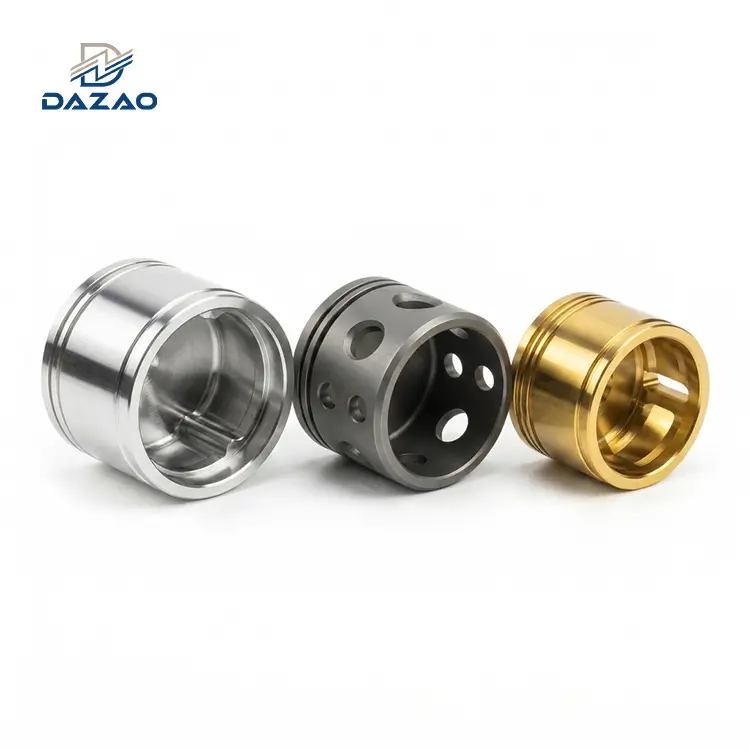

Optimizing pocket design cnc configurations requires balancing tool reach, internal corner radii, and workpiece stiffness against cutting physics. Machining costs escalate non-linearly once cavity depth exceeds 3 to 4 times the cutter diameter due to tool deflection scaling with the cube of length and inversely with the fourth power of diameter. To prevent chatter, tool breakage, and wall taper, designers must specify internal corner radii at least 15% larger than the tool radius, account for toolholder clearance envelopes in stepped pockets, and maintain a minimum floor thickness of 2.0 mm to avoid residual stress warping.

CAD Geometry vs. Physical CNC Machining Constraints
The Visual Extrusion Trap in 3D CAD Modeling
In CAD software, creating a rectangular or freeform pocket requires a single cut-extrude operation. In physical manufacturing, that same feature dictates machine kinematics, cutting tool rigidity, spindle load limits, chip clearance paths, and cycle times. A feature that takes three seconds to model can multiply the final CNC pocket machining cost significantly if internal cavity dimensions violate tooling physics during high-precision CNC milling operations.
When procurement teams and mechanical engineers release part drawings to external machine shops, deep closed pockets represent a primary driver of engineering change orders, delayed lead times, and quote rejections. The breakdown occurs because 3D solid models display geometry as rigid, unyielding volumes. They omit the dynamic cutting forces, spindle reach limitations, and vibrational resonance that occur when an end mill enters raw stock.
Case Study: Al6061 Optical Cavity Production Run
At the Xiamen Dazao Machinery production facility, our engineering team reviewed a production run of 120 optical sensor enclosures milled from Al6061-T6. The original customer model featured an internal pocket 85 mm deep by 30 mm wide, with sharp R1.5 mm internal vertical corners and an un-reinforced 1.2 mm floor thickness. The customer drawing specified a standard linear tolerance of ±0.05 mm, a floor flatness of 0.03 mm, and a surface finish requirement of Ra 0.8 µm.
Executing this feature as originally drawn required a 3 mm diameter micro-mill with an overhang-to-diameter ratio exceeding 28 to 1 to clear the corners. The resulting setup caused immediate tool chatter, severe wall taper, surface roughness spikes beyond Ra 3.2 µm, and three broken solid carbide tools within the first two setup pieces. Following our review under DFM guidelines for aluminum machining, redesigning the part with step-down draft angles, an increased internal corner radius of R4.0 mm, and a 2.5 mm floor thickness reduced the machining cycle time per unit from 48 minutes to 11 minutes while maintaining all functional optical sensor interfaces.
Cavity Depth, Overhang Physics, and Tool Deflection
The Cubic Tool Deflection Law in Deep Cavities
The primary physical constraint in deep pocket CNC machining is tool deflection. When an end mill engages material, radial cutting forces push the tool tip away from the programmed toolpath.
Under the principles of beam mechanics, the physical deflection of a cylindrical cutting tool is directly proportional to the cutting force multiplied by the cube of tool overhang length. Furthermore, deflection is inversely proportional to the tool material elastic modulus multiplied by the fourth power of the tool diameter.
Because deflection scales with the cube of tool length and inversely with the fourth power of tool diameter, doubling the tool reach without changing its diameter increases deflection by a factor of 8. Conversely, halving the tool diameter at a fixed overhang increases CNC pocket tool deflection by a factor of 16.
|
Overhang-to-Diameter (L/D) Ratio |
Deflection Factor (vs. 3D Baseline) |
Rigidity Retention |
Permissible Radial Engagement |
|
3:1 (Standard Reach) |
1.0x (Baseline) |
100% |
Up to 40% tool diameter |
|
4:1 (Extended Reach) |
2.37x |
42% |
Up to 20% tool diameter |
|
5:1 (Long Reach) |
4.63x |
22% |
Up to 10% tool diameter |
|
6:1 (Severe Overhang) |
8.0x |
12.5% |
Up to 5% tool diameter |
|
8:1 (Extreme Deep Pocket) |
18.96x |
5.3% |
Up to 2% tool diameter |
|
10:1 (Critical Limit) |
37.04x |
2.7% |
Micro-step dynamic milling only |
Depth-to-Width Ratios and Toolholder Envelope Clearance
According to standard CNC pocket design guidelines, cavity depth should ideally remain within 3 to 4 times the cutting tool diameter. Determining the safe CNC pocket depth tool diameter limit ensures stable chip load without chatter. For general cavity geometry, the CNC pocket depth to width ratio should not exceed 3 to 1 for standard 3-axis setups.
When evaluating how deep can a CNC pocket be, machining centers can execute pockets up to 8 to 10 times tool diameter, but doing so shifts the process from standard dynamic roughing to specialized, high-cost manufacturing.
|
Cavity Depth Category |
Depth to Tool Diameter Ratio |
Tooling Setup |
Process Risk Profile |
|
Shallow Pocket |
Up to 2x Tool Diameter |
Stub Length Solid Carbide |
Low risk, maximum feed rates |
|
Standard Pocket |
3x to 4x Tool Diameter |
Standard Flute End Mill |
Controlled roughing, reliable tolerance |
|
Deep Pocket |
5x to 6x Tool Diameter |
Necked-Down Carbide Tool |
Reduced feed, chatter suppression required |
|
Extreme Cavity |
Over 6x Tool Diameter |
Tuned Damped Boring / 5-Axis |
High cost, multiple light finishing passes |
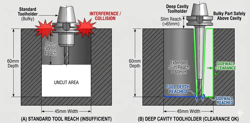
A common design oversight in CNC deep pocket design is checking only tool flute length while ignoring the physical envelope of the toolholder, such as an ER32 collet chuck, hydraulic chuck, or heat-shrink holder. When a pocket exceeds 50 mm in depth, an end mill cannot simply stick out 60 mm from the collet without severe deflection. The toolholder body has a substantial diameter; for example, an ER32 collet nut has an outer diameter of 50 mm. If the pocket opening is 40 mm wide and 60 mm deep, the collet nut will physically collide with the top perimeter of the workpiece before the tool reaches the bottom floor.
To machine such features without holder collision:
· The designer should open the cavity upper profile with a stepped counter-bored geometry.
· The machine shop must deploy slim-line shrink-fit holders, which carry lower clamping torque and require lighter cuts.
· The designer should apply a draft angle of 1 to 3 degrees on cavity sidewalls, providing progressive clearance as the cutter steps down.
Internal Corner Radius Selection and Tool Path Kinematics
Cutting Tool Engagement Spikes at Inside Corners
The selection of the internal vertical CNC pocket corner radius directly governs machine acceleration, radial engagement angles, and the emergence of structural chatter marks.
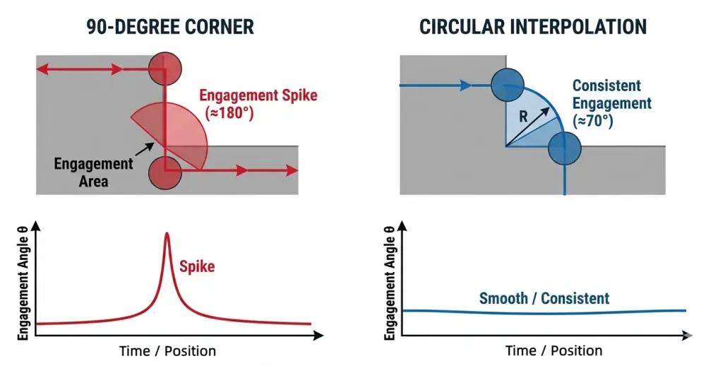
When an end mill travels along a straight sidewall, the radial engagement angle is typically low, averaging 30 to 60 degrees. As the cutter enters a sharp 90-degree inside corner where the pocket radius matches the tool radius exactly, the tool contacts material across an engagement arc of 180 degrees.
This sudden surge in radial engagement causes:
· Instantaneous increase in radial cutting pressure, forcing the tool tip away from the corner.
· Severe high-frequency chatter marks across both intersecting sidewalls, violating standard surface roughness specifications for milled pockets.
· Micro-chipping along carbide cutting edges, accelerating tool wear.
· Axis deceleration down to near-zero feed, causing dwell marks and heat buildup.
The 15% Corner Radius Oversize Rule for High-Speed Milling
To maintain continuous tool motion and allow high-speed trochoidal cornering paths, the programmed internal corner radius must always be larger than the radius of the cutting tool. Adhering to internal corner radius cost optimization principles keeps machine feed rates steady and avoids tool stalling.
The practical rule for internal corner radii specifies that the programmed corner radius must be equal to or greater than 1.15 times the cutting tool radius.
|
Target Cutting Tool Diameter |
Minimum Inside Corner Radius |
Preferred DFM Corner Radius |
Feasible Milling Toolpath |
|
3.0 mm (1/8 inch) |
1.75 mm |
2.0 mm to 2.5 mm |
Smooth circular interpolation |
|
6.0 mm (1/4 inch) |
3.45 mm |
4.0 mm to 5.0 mm |
Continuous adaptive cornering |
|
10.0 mm (3/8 inch) |
5.75 mm |
6.5 mm to 8.0 mm |
High-speed trochoidal milling |
|
12.0 mm (1/2 inch) |
6.90 mm |
8.0 mm to 10.0 mm |
High-efficiency dynamic path |
|
16.0 mm (5/8 inch) |
9.20 mm |
10.5 mm to 12.0 mm |
Heavy roughing with corner blend |
Specifying a completely sharp bottom corner where the sidewall meets the floor requires an end mill with square corners. Square-end tooling concentrates cutting stress at the sharp tips, making the tool prone to chipping under high chip loads. Adding a floor-to-wall blend fillet radius of 0.5 mm to 2.0 mm allows the use of bull-nose end mills, distributing cutting pressure across a radius and extending tool life by more than three times.
Floor Thickness, Residual Stresses, and Warping Control
Oil-Canning Buckling and Vacuum Fixturing Fallacies
Specifying an excessively thin CNC pocket floor thickness introduces structural instability during cutting and geometric distortion after part unclamping. In high-speed milling, raw stock billets contain internal residual stresses from quenching and stretching operations unless engineers select stress-relieved aluminum material grades such as Al6061-T651. When a tool removes 80% to 90% of the raw block to form a deep cavity, internal stresses re-equilibrate, causing thin floors to bow.
Under plate bending mechanics, floor deflection under axial tool plunging loads is inversely proportional to the cube of floor thickness. Reducing the floor thickness from 3.0 mm to 1.0 mm increases floor flexing during cutting passes by 27 times.
When the floor thickness drops below 2.0 mm across a pocket wider than 50 mm by 50 mm, the bottom plate exhibits oil-canning behavior, snapping between concave and convex shapes under light thumb pressure.
During machining, workholding forces often conceal this instability:
· Vacuum Fixturing Distortion: The vacuum chuck pulls the thin floor flat against the baseplate while the bottom finishing end mill cuts the surface flat. Once vacuum is released, elastic recovery springs the floor upward, producing a crowned center that violates achievable aluminum machining tolerances.
· Mechanical Clamping Strain: Torquing mechanical vise jaws compresses the workpiece perimeter. Once the pocket center is hogged out, the weakened bottom buckles under residual clamping strain.
Stress-Relief Protocols and Structural Rib Integration
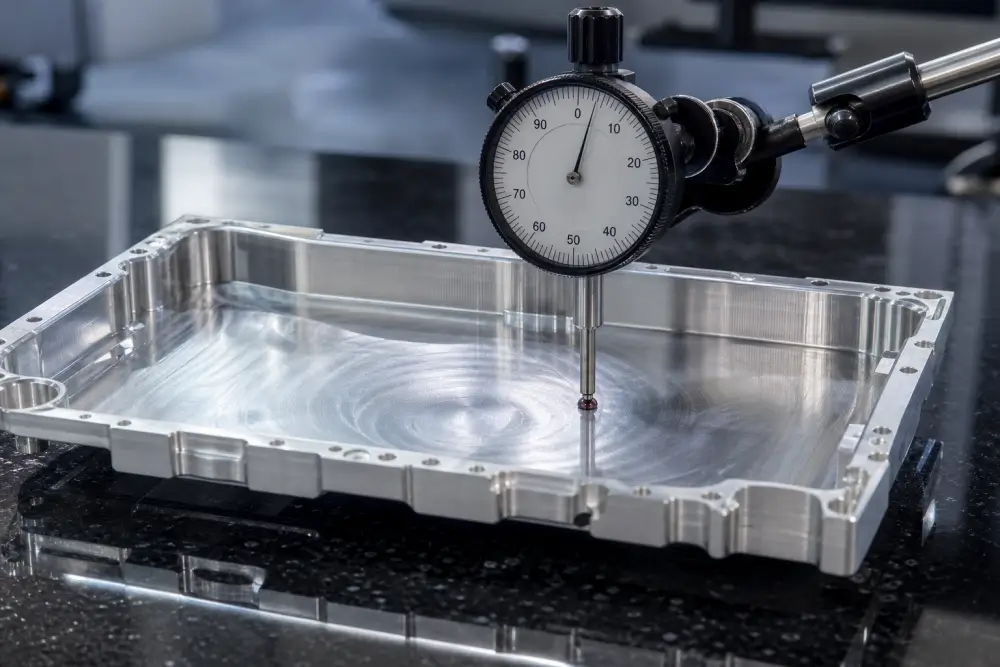
To maintain floor flatness within ±0.020 mm on deep cavities while respecting minimum wall thickness engineering rules, Dazao implements the following shop-floor techniques:
|
Pocket Floor Span Area |
Minimum Solid Floor Thickness |
Recommended Structural Feature |
Expected Flatness Deviation |
|
Under 30 mm x 30 mm |
1.0 mm to 1.5 mm |
Solid flat floor |
Within ±0.015 mm |
|
30 mm x 30 mm to 100 mm x 100 mm |
2.0 mm to 3.0 mm |
Perimeter step transition |
Within ±0.025 mm |
|
100 mm x 100 mm to 250 mm x 250 mm |
3.5 mm to 5.0 mm |
Integrated cross-rib grid |
Within ±0.035 mm |
|
Over 250 mm x 250 mm |
Greater than 5.0 mm |
Honeycomb stiffener ribs |
Within ±0.050 mm |
· Two-Stage De-Stressing Roughing: Rough out the main cavity leaving 1.0 mm of stock on the floor and walls, release the part from the vise completely to permit stress relaxation, then lightly reclamp with calibrated torque (5 to 8 Nm) for finishing passes.
· Integrated Stiffener Ribs: Instead of machining an expansive 1.5 mm flat floor, incorporate intersecting 3.0 mm wide by 4.0 mm high reinforcement ribs across the floor. This increases structural section modulus by over 400% while achieving targeted weight reduction goals.
Chip Packing, Evacuation Dynamics, and Thermal Welding
Recutting Mechanics and Built-Up Edge in Blind Pockets
In deep cavity operations, chip clearance dictates tool survival. When cavity depth exceeds 3 times tool diameter, chips struggle to escape the pocket opening due to air turbulence and gravity.
When milling aluminum alloys at peripheral cutting speeds of 300 to 800 m/min according to aluminum alloy CNC machining characteristics:
· Standard flood coolant nozzles create hydraulic backpressure and fluid swirls at the pocket opening, failing to penetrate to the bottom cutting zone.
· Evacuated chips lose upward velocity, fall back into the cutting path, and get caught between the tool flutes and pocket sidewalls.
· The cutting edges recut these loose chips, generating localized frictional temperatures exceeding 450 °C.
This extreme thermal spike causes ductile aluminum alloys like Al6061-T6 to plasticize and friction-weld directly onto the carbide tool flutes, forming a destructive built-up edge. Once flutes clog with welded aluminum chips, cutting action stops and the tool shanks snap instantly.

Through-Spindle Air Blast and Bottom Relief Vents
To maintain steady chip evacuation without risking chip packing:
|
Pocket Depth Ratio |
Evacuation Medium |
Pressure Standard |
Primary Evacuation Mechanism |
|
Up to 2x Tool Diameter |
Standard Flood Coolant |
0.2 to 0.5 MPa |
Liquid wash and gravity float |
|
3x to 5x Tool Diameter |
High-Pressure Air Blast |
0.6 to 0.8 MPa |
Continuous dynamic chip blowout |
|
5x to 8x Tool Diameter |
Through-Spindle Air |
1.5 to 3.0 MPa |
Direct axial flute chip ejection |
|
Over 8x Tool Diameter |
High-Pressure Coolant |
Greater than 5.0 MPa |
Forced hydraulic evacuation |
Where sealed enclosure requirements are not mandatory, incorporating standard hole drilling and venting practices by placing 3.0 mm to 6.0 mm relief drain holes at bottom corners converts blind pockets into open flow channels. This allows gravity, coolant, and chips to exit freely through the bottom of the fixture.
In-Depth Pocket Machining Cost Model
Tooling Depreciation and Metal Removal Rate Penalties
Machining costs for pocket features increase non-linearly once cavity depth exceeds standard catalog tooling lengths. Designers can apply cost reduction strategies for aluminum machining to keep tooling budgets under control.
The total machining cycle time for a cavity increases roughly with the square of the ratio between actual depth and three times the tool diameter.
|
Depth-to-Diameter Ratio |
Feed Rate Scaling |
Tooling Category |
Scrap Risk Index |
Cost Multiplier |
|
2:1 (Shallow Cavity) |
100% (Baseline Feed) |
Standard 3-Flute Carbide |
Under 0.5% |
1.0x (Base Cost) |
|
3:1 (Standard Depth) |
90% to 100% |
Standard Reach End Mill |
Under 1.0% |
1.25x |
|
4:1 (Deep Pocket) |
50% to 65% |
Necked-Down Carbide Tool |
2.0% to 3.0% |
2.2x |
|
6:1 (Severe Cavity) |
25% to 35% |
Extended Damped Shank |
5.0% to 8.0% |
4.5x |
|
8:1 (Extreme Depth) |
10% to 18% |
Heavy Metal Carbide Bar |
Over 12.0% |
8.0x+ |
Three major factors drive this cost curve:
· Tooling Purchase and Wear: A standard 10 mm 3-flute end mill costs approximately $30. An extended-reach 10 mm anti-vibration tool with DLC coating costs $160 to $240, while enduring only a fraction of standard tool life under heavy chip loads.
· Metal Removal Rate Reductions: To keep deflection under 0.02 mm, programmers must drop radial engagement from 40% down to 5%, and reduce feed per tooth by over 60%.
· Sequential Rest-Milling Passes: Deep pockets with tight corner radii require multiple intermediate step-down operations using progressively smaller end mills, multiplying cycle time and tool change frequency.
Monolithic Deep Milling vs. 5-Axis Indexing vs. Split Assemblies
When analyzing part manufacturing economics, evaluating 3-axis versus 5-axis machine selection trade-offs reveals clear cost boundaries for deep pocket geometry.
|
Production Factor |
Monolithic 3-Axis Deep Mill |
3+2 Positional 5-Axis Mill |
Two-Piece Split Assembly |
|
Tool Overhang Required |
Extreme (Full pocket depth) |
Short (Tilted tool clearance) |
Minimal (Short stub end mills) |
|
Feed Rate Capability |
15% to 30% of standard |
75% to 90% of standard |
100% full-rate roughing |
|
Tooling Cost per Batch |
High (Specialized long reach) |
Standard catalog tooling |
Low standard tooling |
|
Assembly Labor Cost |
None (Single solid component) |
None (Single solid component) |
Fasteners, dowels, and O-rings |
|
Unit Cost at Q=100 |
$88.00 per unit |
$46.50 per unit |
$38.00 per unit |
DFM Verification Checklist and Alternative Manufacturing
Engineering Self-Inspection Workflow
Before submitting CAD models to Dazao for production quoting, verify your pocket geometry against the following step-by-step checklist:
1. Check Pocket Depth Relative to Tool Diameter: Ensure standard pocket depth does not exceed 3 to 4 times the maximum allowable cutter diameter based on corner radii.
2. Apply the 15% Corner Radius Rule: Verify that all vertical inside corner radii measure at least 1.15 times the nominal radius of the intended milling tool.
3. Verify Floor-to-Wall Blend Radii: Add a 0.5 mm to 2.0 mm transition fillet along the floor perimeter to enable the use of rigid bull-nose cutters.
4. Confirm Bottom Floor Thickness: Maintain a floor thickness of at least 2.0 mm for spans under 100 mm, and 3.5 mm or more with structural ribs for larger areas.
5. Inspect Toolholder Clearances: Check whether the upper cavity opening accommodates standard collet chuck diameters without body collisions.
Sinker EDM, Wire EDM, and Hybrid Additive Strategies
When functional specifications demand deep features that exceed conventional milling limits, Dazao integrates alternative non-traditional machining processes:
|
Extreme Geometry Condition |
Recommended Manufacturing Process |
Technical Justification |
|
Sharp 90° Inside Vertical Corner |
Sinker EDM (Die Sinking) |
Zero radius corners (R0.05 mm) with copper electrodes |
|
Deep Narrow Slot Profile (Width < 3 mm) |
Wire EDM Cutting |
Deflection-free vertical cuts up to 300 mm deep |
|
Depth to Diameter Ratio Exceeding 10:1 |
5-Axis Continuous Undercutting |
Tilting head maintains rigid short-tool engagement |
|
Enclosed Complex Cooling Channels |
Metal 3D Printing + CNC Finishing |
Unconstrained internal fluid cavities with CNC interfaces |

FAQs
01.How do machinists resolve sharp inside square corners without EDM?
02.Why does cavity sidewall taper occur during deep CNC pocketing?
03.What causes thin pocket floors to warp after removal from vacuum tables?
04.How can chip packing and tool breakage be avoided in deep blind aluminum cavities?
05.Why do bottom finishing steps leave witness mismatch marks in deep pockets?
06.When is it cheaper to switch from deep pocket milling to sinker EDM?