


Internal corner radii dictate tool diameter, tool reach, deflection limits, and cutting dynamics. Setting an internal corner radius equal to or smaller than standard end mill dimensions triggers severe cutter engagement spikes, tool chatter, and cycle time inflation. Specifying a corner radius at least 15% to 30% larger than the tool radius enables continuous high-speed circular interpolation, reduces cutting forces by over 60%, and eliminates multi-stage rest machining or secondary sinker EDM operations.
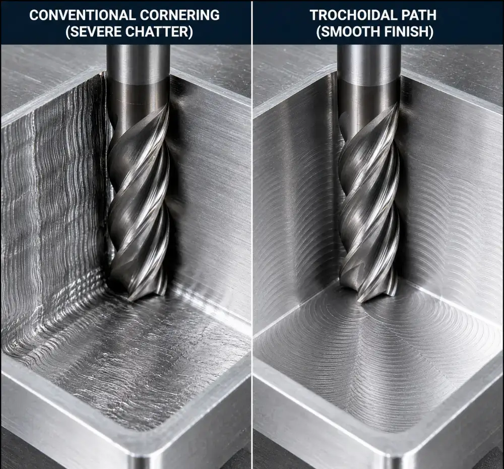
Internal Corner Radius in CAD Modeling vs Shop-Floor CNC Kinematics
In parametric CAD software, drawing a pocket with vertical 90-degree internal edges or assigning a blanket fillet such as R0.5 mm takes seconds. On a 3-axis or 5-axis machining center executing precision CNC machining services, that geometric selection dictates every upstream and downstream manufacturing parameter in multi-axis CNC milling operations.
When a design specifies a corner radius cnc feature that ignores physical machining kinematics, production shifts from efficient volumetric material removal to slow, high-risk micro-milling. The CNC internal corner radius determines:
1. The maximum allowable end mill shank and cutting diameter.
2. The required tool overhang length and resulting tool assembly stiffness.
3. The cutting toolpath strategy: linear point-to-point, circular interpolation, or multi-pass rest milling.
4. The surface roughness (Ra) profile on pocket side walls and transition floors.
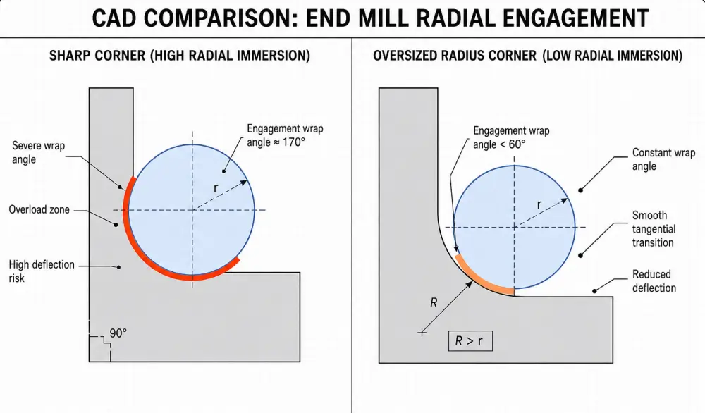
Why Digital CAD Fillets Fail on Physical CNC Milling Machines?
CAD systems treat geometry as massless mathematical boundaries. A vertical edge has no physical resistance. In a CNC machine spindle, however, material removal is governed by rotational torque, chip load per tooth, and cutter engagement limits.
When an end mill runs along a straight wall, the radial width of cut remains constant. When that same tool enters an internal corner with an identical radius, the physical contact area expands instantly. If the CAD model forces a sharp corner or an undersized radius, the physical cutter is subjected to severe mechanical over-engagement, leading to deflection, dimensional taper, and edge chipping.
Case Analysis at Dazao: Tool Breakage in Deep Al7075-T6 Cavities
At the Xiamen Dazao Machinery facility, an aerospace client submitted an order for a structural aluminum CNC machining project involving an Al7075-T6 optical housing. The design featured a rectangular cavity 35 mm deep with an internal corner radius specified at R0.5 mm. The drawing applied a general title block tolerance of +/- 0.02 mm and an internal surface finish requirement of Ra 0.8 micrometers.
The production outcome illustrates why corner radius selection governs part manufacturability:
· Tool Selection: To machine an R0.5 mm corner, the maximum cutter diameter is 1.0 mm.
· Tool Overhang Ratio: Reaching a 35 mm depth with a 1.0 mm solid carbide end mill creates an extreme length-to-diameter (L/D) ratio of 35:1.
· Mechanical Failure: Standard carbide end mills lose rigid stability past an L/D ratio of 4:1. During roughing with a 12 mm tool followed by a secondary 3 mm tool, the final 1.0 mm long-neck finisher encountered chip packing and deflection spikes. Two successive micro-end mills fractured due to cyclical fatigue and resonance.
· Component Scrap: Severe tool chatter generated an unacceptable surface finish of Ra 3.2 micrometers along the corner junction, and lateral cutter deflection created a dimensional taper of +0.06 mm from top to bottom. The batch was rejected at initial CMM inspection.
· The Engineering Fix: Dazao engineers initiated a Design for Manufacturability (DFM) review, proposing an increase of the corner radius from R0.5 mm to R4.0 mm, alongside a 1.5-degree draft angle on the non-mating corner walls. This permitted the use of a rigid 6 mm end mill (L/D ratio approx 5.8:1), slashing cycle time per cavity from 114 minutes to 16 minutes while achieving a consistent Ra 0.6 micrometer finish without tool failure.
Cutter Engagement Angle (CEA) Dynamics and Internal Corner Tool Loading
Machining linear paths involves steady-state cutting dynamics. When an end mill enters an inside corner, cutting forces change from constant loads to dynamic force spikes.
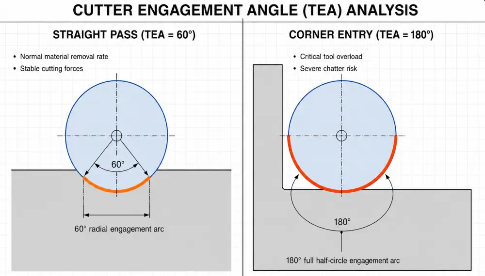
Physics of the 180-Degree Corner Engagement Spike
In a straight pocket wall pass with a radial depth of cut equal to 25% of the cutter diameter, the Cutter Engagement Angle remains stable at approximately 60 degrees:
Cutter Engagement Angle = arccos(1 - (2 x Radial Depth of Cut / Cutter Diameter)) = arccos(1 - 0.5) = 60 degrees
When the tool reaches a sharp 90-degree corner where the CNC corner radius tool diameter matches the pocket feature radius (Corner Radius = Tool Radius), the cutter stops moving linearly along one axis and pivots. At the exact corner apex, the tool contact wrap angle instantly expands from 60 degrees to 180 degrees.
This sudden threefold expansion in tool-workpiece contact causes severe physical reactions:
· Radial Force Surge: Radial cutting force scales non-linearly with engagement angle. As contact wraps around half the tool circumference, radial force spikes by 250% to 400%, pushing the tool tip away from the programmed path.
· Thermal Shock and Chip Jamming: Chip evacuation space inside the flute flattens to zero at the corner vertex. Compressed chips weld to the carbide flutes, inducing catastrophic micro-chipping along the tool flutes and tool edges.
· Chatter Harmonics: The sudden increase in mechanical load excites the natural frequency of the tool-holder assembly, leaving visible washboard chatter patterns across the vertical corner walls.
Radial Chip Thinning and Controller Feed Rate Compensation
During circular interpolation around an internal corner, the center of the tool travels along an arc with a radius smaller than the nominal corner radius being cut:
Tool Centerline Radius = Corner Radius - Tool Radius
If the machine controller maintains a constant programmed linear feed rate at the tool centerline, the actual peripheral feed rate at the outer cutting edge increases substantially:
Actual Peripheral Feed Rate = Programmed Centerline Feed Rate x (1 + (Tool Radius / Tool Centerline Radius))
When Corner Radius equals Tool Radius, the Tool Centerline Radius approaches zero, causing the peripheral feed rate to spike theoretically toward infinity. Modern CNC controls attempt to decelerate, but axis lag frequently results in over-engagement, tool deflection, and gouging.
The Dazao Benchmark: Why Corner Radius Must Exceed Tool Radius by 15% to 30%
To ensure consistent chip loads and avoid dead-stop corners, internal corner radii must always exceed tool radii:
Recommended Corner Radius >= 1.15 to 1.30 x Tool Radius
This geometric clearance allows CAM software to generate a continuous trochoidal or adaptive circular toolpath. The cutter rolls through the corner rather than stopping and pivoting, maintaining a continuous engagement angle under 90 degrees, reducing radial deflection forces by over 60%, and extending end mill operating life threefold.
Pocket Depth vs Internal Corner Radius: Managing Tool Deflection and Rest Machining
Specifying an internal corner radius without referencing pocket depth is one of the most common causes of machining delays and inflated component costs. When evaluating complex cavities in 3-axis versus 5-axis CNC machining, tool reach and holder clearance dictate the minimum achievable radius.
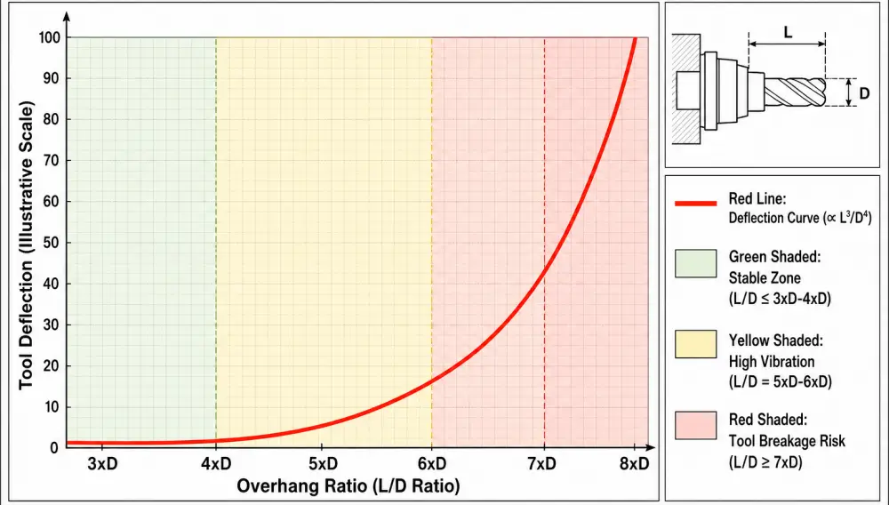
Cantilever Beam Deflection Formula and the L/D Ratio Trap
A solid carbide end mill under lateral cutting load acts as a cantilever beam fixed at the tool holder collet. Elastic deflection at the tool tip is calculated via classical beam mechanics:
Tool Deflection = (Radial Cutting Force x Overhang Length^3) / (3 x Modulus of Elasticity x Area Moment of Inertia)
Where Area Moment of Inertia for a solid cylindrical beam is (Pi x Tool Diameter^4) / 64. Substituting this value yields the final deflection formula:
Tool Deflection = (64 x Radial Cutting Force x Overhang Length^3) / (3 x Pi x Modulus of Elasticity x Tool Diameter^4)
Because deflection scales with length cubed (Overhang Length^3) and inversely with diameter to the fourth power (Tool Diameter^4), holding depth constant while reducing tool diameter to fit a small CNC pocket corner radius design causes deflection to explode exponentially. This dynamic interlocks directly with CNC wall thickness DFM guidelines, where thin cavity walls flex alongside the deflected cutter.
|
Tool Diameter |
Corner Radius |
Overhang Length |
L/D Ratio |
Relative Deflection Factor (Proportional to L^3 / D^4) |
Stability Status |
Recommended Maximum Feed Derating |
|
12.0 mm |
R7.0 mm |
36 mm |
3:1 |
1.0x (Baseline) |
Optimal Rigid Zone |
100% nominal feed |
|
8.0 mm |
R5.0 mm |
36 mm |
4.5:1 |
5.06x |
Stable with minor vibration |
75% nominal feed |
|
4.0 mm |
R2.5 mm |
36 mm |
9:1 |
81.0x |
High deflection and chatter risk |
30% nominal feed, multi-step depth |
|
2.0 mm |
R1.2 mm |
36 mm |
18:1 |
1,296.0x |
Severe instability; tool breakage zone |
10% nominal feed, high cycle time |
|
1.0 mm |
R0.6 mm |
36 mm |
36:1 |
20,736.0x |
Impossible for milling; requires EDM |
Secondary process required |
Cycle Time Inflation in Multi-Stage Rest Machining Operations
When a pocket features large overall dimensions but tight corner fillets, machining cannot be completed with a single tool. The CAM programmer must implement multi-stage rest milling:

1. Primary Roughing (Bull-Nose End Mill, e.g., Diameter 16 mm, R2): Removes 85% to 90% of raw billet stock at high feed rates (4500 mm/min). Large unmachined triangular volumes remain in every vertical corner.
2. Semi-Finishing Rest Mill (e.g., Diameter 6 mm): Removes corner stock left by the 16 mm cutter. Feed rate must drop by 50% due to unequal material engagement.
3. Corner Finishing Micro-Mill (e.g., Diameter 2 mm): Cleans the final corner contour. Because radial engagement varies as it enters uncut zones, feed rate must be derated to prevent tool breakage.
4. Resulting Cost Impact: Each additional rest machining step adds tool change cycles, tool wear monitoring overhead, and feed rate throttling, multiplying total cycle time by 2.5x to 4x compared to a cavity designed for uniform tool paths.
Engineering Selection Matrix for Pocket Depth and Corner Fillets
To maintain strict control over the CNC corner radius and pocket depth relationship, mechanical designers should apply the following radius-to-depth parameters to ensure the minimum internal corner radius CNC machining limits are respected:
|
Pocket Depth Category |
Depth-to-Width Geometry |
Minimum Internal Corner Radius |
Preferred Internal Corner Radius |
Manufacturing Strategy |
|
Shallow Cavity |
Depth <= 2 x Tool Diameter |
Corner Radius >= 0.10 x Depth |
Corner Radius >= 0.25 x Depth |
Single-pass high-speed milling with standard flute cutters |
|
Medium Cavity |
2 x Tool Diameter < Depth <= 4 x Tool Diameter |
Corner Radius >= 0.15 x Depth |
Corner Radius >= 0.35 x Depth |
Two-stage roughing and finishing with neck-relieved end mills |
|
Deep Cavity |
Depth > 4 x Tool Diameter |
Corner Radius >= 0.25 x Depth (or 1.5-degree Wall Draft) |
Corner Radius >= 0.50 x Depth |
Multi-stage adaptive rest milling, long-neck cutters, or wire EDM |
Floor-to-Corner Deflection Steps: Root Causes and CMM Inspection Risks
When analyzing CNC inside corner radius for pocket machining, standard design manuals focus exclusively on vertical wall finish. On the production floor at Xiamen Dazao Machinery, CMM rejection data reveals that geometric failures often occur at the junction between the vertical corner radius and the horizontal floor.
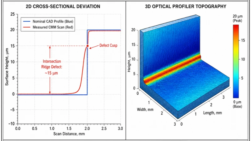
3D Cutting Force Vector Shifts at Corner Vertices
During linear pocket floor clearing, cutting forces remain largely planar. As an end mill transitions into a tight corner, cutting forces become complex three-dimensional vectors:
1. Radial Force Vector: Pushes the tool shank away from the corner apex along the bisection angle.
2. Axial Force Vector: Created by helix upcut action, pulling the tool axially downward into the workpiece or pushing it upward depending on flute helix direction.
3. Tangential Cutting Force: Spikes due to increased instantaneous chip volume.
When the machine controller detects a tight radius, it commands axis deceleration to respect acceleration limits. As table velocity drops, radial cutting pressure relaxes abruptly.
The flexed end mill springs back toward its unconstrained equilibrium position. This mechanical spring-back causes the bottom cutting lip to bite deeper into the pocket floor at the exact entry and exit points of the corner arc, leaving a distinct gouge or raised step measuring between 0.015 mm and 0.045 mm.

Assembly Failures Caused by Bottom Step Ridges
This floor-to-corner step defect causes immediate functional failures when verifying parts against tight CNC machining tolerances:
· Planar Interference on Mating Components: Mating circuit boards, lithium-ion battery modules, or optical sub-assemblies cannot seat flush against the pocket floor, causing angular tilt and thermal interface material thickness variation.
· Localized Stress Risers: The step acts as a microscopic notch, concentrating dynamic cyclic loads and lowering fatigue thresholds in structural automotive and aerospace components.
· Bearing Bore Runout: When internal corners form locating features for precision bearings, floor steps cause axial misalignment and premature bearing race wear.
Resolving Floor Steps with Toroidal Bottom Blend Radii
To eliminate the floor-to-corner step, design engineers should avoid calling out a perfectly sharp 90-degree floor-to-wall intersection alongside a small vertical corner radius. Specifying a compound corner with a bottom blend radius (Bottom Radius >= 0.5 mm to 1.5 mm) enables the use of bull-nose (toroid) end mills.
Corner-radius bull-nose cutters distribute cutting forces across a continuous toroidal curve, preventing axial gouging and producing uniform floor-to-wall transitions without secondary manual deburring.
Designing for Square Mating Parts: Dogbone Fillets vs EDM Processes
Standard mechanical design frequently requires rectangular components (such as busbars, core pins, connectors, or sliding blocks) to seat completely inside a recessed pocket. Applying sound aluminum enclosure DFM design principles prevents unnecessary secondary tooling setups.
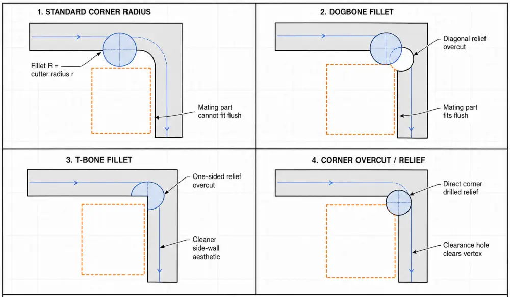
Mechanical Relief Comparison: Dogbone, T-Bone, and Overcut Geometry
When functional assembly requires square clearance without adding secondary manufacturing stages, dogbone fillet CNC machining provides a practical solution.
|
Relief Geometry Type |
Toolpath Complexity |
Maximum Mating Clearance |
Stress Concentration Factor (Kt) |
Best Fit Application |
|
Standard Fillet (Radius >= Tool Radius) |
Lowest (Continuous Arc) |
Poor (Requires mating part chamfer) |
1.2 to 1.5 (Low) |
Fluid manifolds, general structural brackets |
|
Dogbone Fillet |
Low (Corner 45-degree plunge) |
100% full square clearance |
2.2 to 2.8 (Moderate) |
Battery module enclosures, slide-in electronics |
|
T-Bone Fillet |
Moderate (Single-axis over-travel) |
100% full square clearance |
2.5 to 3.2 (Higher) |
Step-mating connectors, tooling fixtures |
|
Diagonal Corner Overcut |
Moderate (Radial slotting path) |
Full clearance with minimal area loss |
2.0 to 2.4 (Moderate) |
Precision sheet metal nesting fixtures |
To ensure complete square clearance with a dogbone fillet in CNC machining square inside corners, the minimum diameter of the relief cutter relative to mating square width must satisfy:
Minimum Relief Tool Diameter >= (Mating Square Width / 1.414) - Clearance Offset
Rotary CNC Milling vs Wire EDM and Sinker EDM Capabilities
When functional or aesthetic requirements demand true sharp corners (Radius < 0.1 mm), rotary CNC milling sharp internal corners is physically impossible, requiring alternative processes.
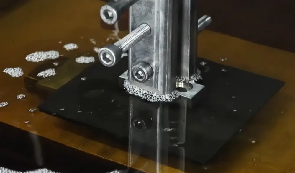
1. Wire EDM (Electrical Discharge Machining):
· Applicability: Through-pockets and open-ended slots only.
· Tolerance and Radius: Achieves internal corner radii as small as R0.03 mm using 0.05 mm brass wire, maintaining tolerances of +/- 0.002 mm.
· Cost Metric: Highly cost-effective for deep through-features compared to micro-milling.
2. Sinker EDM (Ram / Plunge EDM):
· Applicability: Blind pockets and closed-bottom cavities.
· Manufacturing Overhead: Requires precision CNC high-speed milling of high-density copper or graphite electrodes, followed by multi-stage roughing and orbiting spark-erosion setups.
· Cost Metric: Increases individual feature cost by 300% to 600% relative to standard CNC milling.
CNC Corner Radius Machining Cost Modeling and Cycle Time Comparison
Every reduction in internal corner radius triggers an exponential shift in cycle time, tooling consumption, machine hourly rates, and scrap risks. Understanding this correlation is central to reducing custom aluminum CNC machining costs across medium-to-high volume production runs.

Process Route Cost Breakdown: Large Radius vs Small Fillet vs Sinker EDM
The choice of corner radius directly sets the machining route:
· Route A (Optimized Large Fillet): Single setup roughing and finishing with standard rigid cutters. Zero tool changes dedicated exclusively to corner clearing.
· Route B (Sub-Millimeter Fillet): Primary high-speed roughing, followed by two stages of rest machining with long-neck micro-end mills operating at restricted feed rates.
· Route C (Sharp 90-Degree Corner in Blind Cavity): CNC pre-milling, copper or graphite electrode machining, secondary sinker EDM spark erosion, and manual bench polishing to remove EDM recast layers.
Empirical Machining Cost Data on a 100 mm x 100 mm x 40 mm Pocket
To demonstrate how internal radii dictate CNC corner radius machining cost, the following data models a single standard pocket machined in Al6061-T6 on a 4-axis machining center ($85 per hour machine shop rate):
|
Parameter |
Scenario A: DFM-Optimized |
Scenario B: Tight Corner Design |
Scenario C: True Sharp Corner |
|
Internal Corner Radius |
R6.0 mm |
R1.0 mm |
Sharp Corner (Radius <= 0.05 mm) |
|
Primary Roughing Tool |
Diameter 16 mm Bull-Nose (R2) |
Diameter 16 mm Bull-Nose (R2) |
Diameter 16 mm Bull-Nose (R2) |
|
Rest Machining Stages |
None (Single Finishing Tool) |
Stage 1: Diameter 4 mm / Stage 2: Diameter 1.5 mm |
Sinker EDM Setup Required |
|
Secondary Processes |
None |
None |
Graphite Electrode CNC Milling + Sinker EDM |
|
Roughing Cycle Time |
4.2 minutes |
4.2 minutes |
4.2 minutes |
|
Finishing / EDM Cycle Time |
2.6 minutes |
18.5 minutes |
34.0 minutes (EDM burn + setup) |
|
Tooling Wear / Consumption |
Baseline ($1.20) |
High ($8.50 per part due to tool wear) |
High ($18.00 electrode material + wear) |
|
Direct Machining Cost / Part |
$9.64 |
$32.19 |
$72.15 |
|
Relative Cost Multiplier |
1.0x (Baseline) |
3.34x |
7.48x |
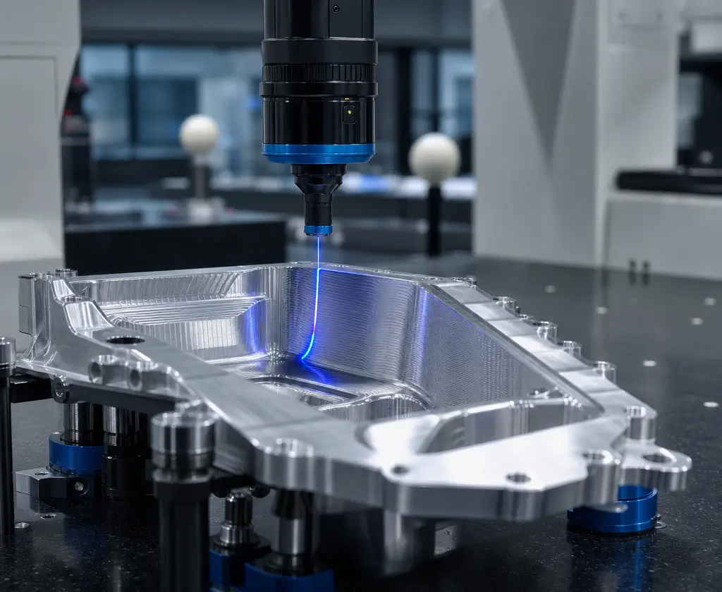
Dazao Engineering DFM Rules for Inside Corner Optimization
To maintain tight dimensional control while reducing production costs, engineering teams should incorporate these practical rules into component drawings.
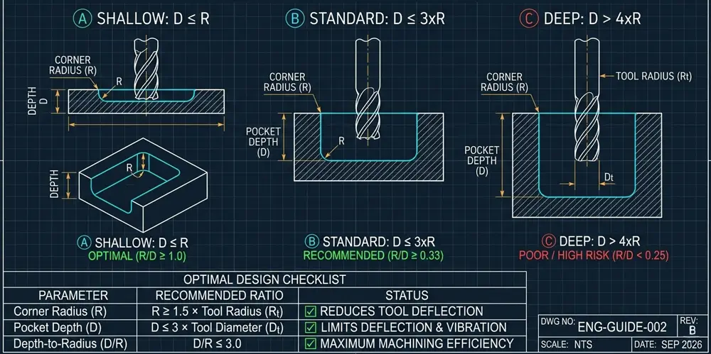
Four Non-Negotiable DFM Rules for Structural Engineers
1. The Fractional Non-Standard Rule: Never specify an internal corner radius that matches an integer tool radius. For instance, do not specify an R3.0 mm corner if you expect the shop to run a standard 6.0 mm cutter (tool radius 3.0 mm). Specify R3.5 mm to R4.0 mm. This provides clearance for the cutter centerline to maintain continuous movement without dwelling at the vertex.
2. The 3:1 Pocket Depth-to-Radius Limit: Keep the ratio of pocket depth to internal corner radius at or below 3:1 for standard pricing:
Pocket Depth to Corner Radius Ratio: (Pocket Depth / Corner Radius) <= 3
If a cavity must reach 30 mm in depth, specify a corner radius of at least R10.0 mm. If the radius must be smaller than R3.0 mm (Ratio = 10), incorporate a multi-tiered step cavity or a 1.5-degree to 3.0-degree draft angle on corner walls to allow heavier, tapered-shank end mills.
3. Maintain Radius Uniformity Across the Part: Avoid calling out R2.0 mm on one pocket, R3.0 mm on another, and R1.5 mm on an exterior slot. Standardizing internal corner radii across all features allows a single finishing tool to execute continuous operations across the component, minimizing tool change cycles and reducing programming time.
4. Separate Wall Radius from Bottom Radius: When designing deep structural housings, keep the vertical wall corner radius large (Radius >= 4.0 mm) while keeping the bottom floor fillet small (Bottom Radius approx 0.5 mm to 1.0 mm). This allows high-rigidity flat or bull-nose end mills to machine both features efficiently without causing chatter marks or floor steps.
Procurement Drawing Audit Checklist for Cost Avoidance
Before releasing production drawings for quote estimation or initiating a functional rapid prototyping phase, procurement managers should audit drawings for three primary red flags:
· Flag 1: Default title-block general tolerances (+/- 0.05 mm) applied to non-critical internal corner fillets, preventing the shop from using oversized roughing cutters.
· Flag 2: Blind pockets with vertical 90-degree corners that lack dogbone or T-bone relief callouts.
· Flag 3: Deep, narrow cavities where Corner Radius is less than 0.15 times Pocket Depth, which indicates extreme tool deflection and high scrap risks.
Optimize Your Custom CNC Components with Dazao Machinery
Eliminate manufacturing delays, tool deflection defects, and unneeded secondary process costs before cutting raw stock. Connect with our engineering department to submit your drawings for engineering DFM review (STEP, IGES, or Parasolid) and receive a detailed manufacturability analysis alongside an accurate production quote from Xiamen Dazao Machinery.

FAQs
01.Why does my CNC machine chatter when the internal radius equals the cutter radius?
02.What is the most practical depth-to-radius ratio for deep CNC pockets?
03.Why do machined pocket corners show an uneven step at the bottom floor?
04.When should engineers specify dogbone fillets instead of Wire EDM?
05.How does rest machining small corner fillets increase manufacturing cycle times?
06.How should internal corner tolerances be specified to prevent inflated machining quotes?





