


Undercut features present distinct manufacturing challenges not because of profile complexity, but because standard end mills cannot reach recessed surfaces along a direct 3-axis spindle vector. Successful CNC undercut design requires aligning groove profiles with standardized cutter geometries, maintaining a minimum 1.5 to 1 neck clearance ratio, accounting for a 70% to 85% feed-rate reduction caused by cantilever tool deflection, and designing accessible inspection datums before releasing drawings to production.
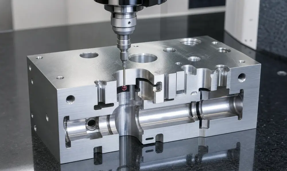
Mechanics of Undercuts and Subtractive Machining Physics
In subtractive manufacturing, an undercut cnc feature refers to any surface geometry that cannot be accessed directly by a standard cylindrical tool along the primary machining axis. While a design engineer can generate a recessed internal groove in a 3D model within seconds, transferring that geometry to raw stock exposes the physical constraints of machine spindle clearance, toolholder reach, and cutting mechanics.
Geometric Occlusion and Machining Reach Limits
The primary disconnect between virtual modeling and physical CNC undercut machining lies in the assumption of line-of-sight tool engagement. A conventional end mill cuts along its periphery and bottom face. When a feature recedes into a sidewall, such as an internal retaining ring groove, an O-ring gland, or an inverted dovetail, the upper workpiece material blocks the spindle path. Thin overhanging lips are also susceptible to severe vibration, requiring adherence to recommended CNC wall thickness thresholds to prevent deflection.
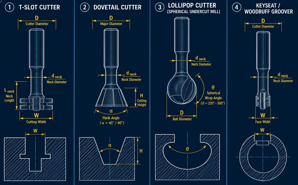
Machining these shielded regions requires specialized geometries:
· Woodruff and keyseat grooving cutters
· Spherical lollipop cutter undercut tools
· Standardized T-slot cutters
· Multi-axis part reorientation on 5-axis platforms
If the design model does not incorporate clearance for the non-cutting neck of the tool shank, the shank will rub against the upper wall at high spindle speeds. This results in severe workpiece galling, localized thermal expansion, and catastrophic tool failure.
Tool Overhang Ratios, Cantilever Physics, and Deflection Realities
When an undercut cutter reaches horizontally beneath an overhanging feature, the tool acts as an unsupported cantilever beam subjected to radial cutting forces. Physical beam mechanics dictate that static deflection at the cutting tip increases directly with the cube of the overhang length from the toolholder to the cutting head.
Simultaneously, tool rigidity is proportional to the fourth power of the neck diameter. A minor 20% reduction in neck diameter to clear an aggressive overhang increases tool deflection by 144%. This physical reality causes cyclic tool chatter, dimensional taper across the undercut wall, poor surface finish exceeding Ra 3.2 micrometers, and accelerated insert edge chipping.
Dazao Production Case: Eliminating Deflection in Al6061 Cavities
At the Xiamen Dazao Machinery manufacturing facility, an automotive customer submitted a 6061-T6 aluminum control module housing specifying a 4.0 mm deep internal undercut located 45 mm down a 12 mm wide slot. The original drawing specified a sharp internal corner with radius under 0.1 mm and a rigid radial tolerance of plus or minus 0.015 mm. Engineers seeking to optimize production budgets can review our technical analysis on evaluating aluminum CNC machining cost factors across complex geometries.
During initial pilot machining using a custom-ground carbide grooving tool with a narrow 3.8 mm neck diameter, the length to diameter ratio reached 12.6 to 1. Radial cutting forces induced a 0.042 mm tool deflection. This caused dimensional taper and cyclic resonance chatter reaching Ra 4.8 micrometers.
Dazao manufacturing engineers conducted a undercut milling DFM review with the client, adjusting the undercut depth from 4.0 mm to 3.0 mm, increasing the neck diameter to 5.5 mm, and adding an internal corner radius of 0.8 mm. This modification reduced tool deflection by 73%, brought the machined tolerance to plus or minus 0.010 mm, achieved an Ra 0.8 micrometer surface finish, and lowered the per-unit machining cycle time by 4 minutes.
Tool Geometry Selection for Standard CNC Undercut Profiles
Selecting the correct feature geometry directly dictates cutter selection, toolpath stability, and production cost. Designing around standard cutting tool profiles prevents the expense and lead time associated with custom ground tooling.
T-Slot Milling Strategies and Slotting Sequences
CNC T-slot machining is standard for machine tables, fixturing plates, and linear clamping rails. Machining a T-slot cannot be executed in a single pass. It follows a strict two-phase protocol:
Phase 1 (Vertical Slotting): A standard square-end mill roughs and finishes the central vertical opening to clear the shank path for the secondary cutter.
Phase 2 (Horizontal Undercutting): A specialized T slot CNC machining cutter enters the slot along the Z-axis, moves to the target depth, and interpolates horizontally to mill the wide lower cavity wings.
Critical geometric rules for T-slots include:
· The bottom clearance beneath the cutting head must be at least 1.0 mm to prevent swarf entrapment between the cutter bottom and the slot base.
· The side overhang depth should not exceed 1.5 times the cutter cutting width.
Dovetail Slotting Dynamics: 45-Degree vs. 60-Degree Geometry
CNC dovetail machining produces angled linear sliding channels and mechanical locking assemblies. Standard industrial dovetail cutters feature included angles of 45 degrees or 60 degrees.
Key engineering constraints:
· Tip Fragility: The acute corner of a dovetail cutter has minimal carbide volume, making it susceptible to heat accumulation and premature chipping. Engineers should specify a 0.2 mm to 0.5 mm bottom corner chamfer or radius rather than an exact sharp internal corner.
· Chip Evacuation Failure: Because the cut is enclosed on three sides, chips become trapped in the acute angle. To prevent surface galling, designs should incorporate a stress-relief slot milled into the bottom face before cutting the dovetail angle.
Internal Retaining-Ring Grooves and Seal Glands
Internal radial grooves house elastomeric O-rings for radial seals or circlips for axial retention. Internal thread reliefs require similar radial cutter clearance as described in our guide on precision CNC thread design and relief standards.
· Bore Entry Limit: The grooving tool must fit through the minor bore diameter while maintaining enough neck reach to cut the groove depth.
· Radial Depth Ratio: The maximum groove depth must remain smaller than half the difference between the pilot bore diameter and the tool shank diameter. Exceeding this threshold forces the toolholder to contact the entry bore edge, causing chatter marks or gouges on the primary seal surface.
Spherical Contouring with Multi-Axis Lollipop Cutters
A CNC lollipop cutter undercut tool features a spherical cutting ball mounted on a narrow cylindrical neck, with spherical wrap angles typically ranging from 220 degrees to 300 degrees. These cutters are used for deburring backside edges, machining undercut seal surfaces, and continuous 5-axis surface finishing on complex organic profiles.
· Clearance Neck Taper: Standard spherical lollipop cutters feature straight or back-tapered necks. Straight necks provide higher rigidity for shallow radial reaches, while tapered necks maximize tool reach clearance during complex 3D toolpath interpolation.
· Surface Speed Inconsistency: The effective cutting diameter on a ball profile drops to zero at the pole. Programming toolpaths for spherical undercut machining requires 3D surface speed compensation in CAM software to avoid poor surface finish along the lower boundary of the feature.
Technical Reference: Standard Undercut Profiles, Tool Constraints & Deflection Risks
|
Undercut Feature Type |
Primary Tooling |
Standard Included Angles / Radii |
Max Depth to Width Ratio |
Recommended Feed Reduction |
Primary Mechanical Failure Mode |
|
Standard T-Slot |
T-Slot Milling Cutter |
90 degree square profile, 0.5 mm corner radius |
1.5 to 1 |
40% to 50% |
Chip packing in wing corners; cutter tooth fracture |
|
Dovetail Slot |
Solid Dovetail End Mill |
45 degree, 60 degree standard |
1.0 to 1 |
55% to 65% |
Chipping of acute cutter tips; thermal build-up |
|
Retaining Ring Groove |
Keyseat / Grooving Insert |
Square with max 0.1 mm edge break |
0.8 to 1 |
30% to 40% |
Shank rubbing against minor bore diameter |
|
Internal O-Ring Gland |
Form Grooving Tool |
Full radius or 0.2 mm corner radius |
1.2 to 1 |
45% to 55% |
Harmonic resonance; seal face waviness exceeding Ra 0.8 |
|
Complex 3D Cavity |
Spherical Lollipop Cutter |
220 to 300 degree spherical wrap |
Geometry dependent |
60% to 80% |
Cantilever deflection; zero-speed center point gouging |
Critical Shop Floor Failure Modes in Undercut Machining
Standard deep undercut CNC guidelines often focus exclusively on static CAD clearances while overlooking dynamic cutting environments. At Dazao, our engineering floor monitors three distinct failure modes that drive up undercut machining cost if not addressed during early DFM reviews.
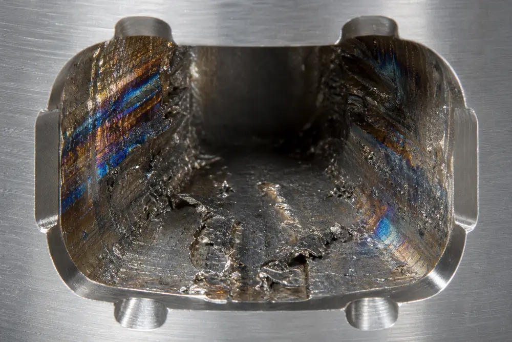
Hydrodynamic Coolant Shielding and Chip Packing in Blind Cavities
When milling internal undercuts inside blind holes or deep pocket sidewalls, standard flood coolant nozzles directed at the external surface cannot reach the cutting zone. Cavity depth restrictions and bottom corner clearance rules align directly with our CNC pocket design guidelines.
The overhanging wall creates a hydraulic barrier:
1. The Air Cavity Trap: The rotational speed of the cutter creates a localized high-pressure boundary layer. This air barrier expels external fluid streams and prevents coolant from reaching the cutting edge. Maintaining stable material removal in high-ductility alloys is detailed in our practical guide on aluminum CNC machining parameters and alloy behavior.
2. Thermal Spike and Micro-Welding: In materials such as 304/316 stainless steel, Inconel 718, and Ti-6Al-4V, lack of coolant lubrication raises cutting zone temperatures above 800 degrees Celsius within seconds. Chips work-harden, weld to the cutter flutes, and cause catastrophic insert breakage. Furthermore, maintaining strict internal seal requirements must account for surface finishing specifications and plating allowances after undercut milling to prevent leakage in dynamic pneumatic or hydraulic systems.
3. The Dazao Production Solution: For deep internal undercuts, Dazao implements through-tool internal coolant delivery at 70 bar minimum pressure or high-pressure micro-lubrication paired with an air blast. When through-tool cooling is unavailable, CAM programmers use a trochoidal peck-grooving routine where the tool cuts for 0.3 mm to 0.5 mm, retracts axially to clear chips, and re-engages, extending tool life significantly.
Metrology Access Limits and Inspection Cost Multipliers
Designing an undercut without verifying inspection access creates severe manufacturing delays. Standard Coordinate Measuring Machines using vertical star-probe styli cannot easily measure recessed internal features:
· Styli Shank Collisions: Measuring an undercut internal ceiling or rear wall requires an articulating CMM head equipped with disc styli or complex star configurations. If the entry opening is small, the CMM stylus shank will contact the outer edge before the ruby tip touches the measured feature.
· Optical Occlusion: Vision systems, optical comparators, and structured-light 3D scanners rely on direct line-of-sight imaging. They cannot capture internal O-ring grooves or T-slot back-faces without cross-sectioning the component.
· Inspection Cost Multipliers: If an engineering drawing specifies a tight profile tolerance on an inaccessible undercut without defined gauge-pin datums, the quality team must create destructive sectioning samples or use high-precision silicone replication polymers. This process can add 20 to 50 USD per part in inspection labor.
Overhang Neck-to-Diameter Ratios and Feed Penalties
The mechanical stiffness of an undercut cutter decreases rapidly as the tool reach increases. In standard end milling, an operator can run an aluminum roughing routine at full feed rates. For an undercut cutter with an extended neck-to-head ratio of 4 to 1 or greater, maintaining that feed load creates severe harmonic chatter.
To prevent chatter and tool breakage, the CAM programmer must apply aggressive feed-rate penalties:
· Length to diameter ratio of 2 to 1: 15% feed reduction
· Length to diameter ratio of 4 to 1: 45% feed reduction
· Length to diameter ratio of 6 to 1: 70% feed reduction
· Length to diameter ratio of 8 to 1 or greater: 85% to 90% feed reduction, requiring multiple light spring passes
Because of this rigidity drop, removing material inside a deep undercut can take 5 to 8 times longer than removing the same volume on an open surface, representing a major driver of elevated production costs.
DFM Rules for Standard Tooling and Clearance (CNC Undercut Dimensions)
Custom form tools carry procurement lead times of two to four weeks and unit costs exceeding 250 to 400 USD per tool. Aligning internal CNC undercut dimensions with cataloged, off-the-shelf tooling configurations eliminates these non-recurring engineering charges and prevents shop floor downtime during batch production.
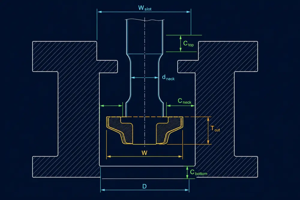
Off-the-Shelf Tool Sizing vs. Custom Grinding Costs
Standard slotting cutters, keyseat cutters, and dovetail end mills conform to established industrial sizing systems such as DIN 650 for T-slots or standard metric keyseat profiles. Aligning CAD features with standard tooling profiles follows the principles outlined in our aluminum CNC machining design manual.
Engineers should establish groove widths and maximum radial depths that correspond directly to standard cutting head widths and shank neck offsets. The maximum safe radial undercut depth should always equal half the difference between the cutter outer diameter and the neck diameter, minus a designated radial safety margin.
Reference Data: Standard Metric Keyseat and T-Slot Tool Clearances
|
Nominal Thread / Slot Standard |
Standard Cutter Outer Diameter (mm) |
Standard Neck Diameter (mm) |
Standard Head Thickness (mm) |
Max Safe Radial Undercut Depth (mm) |
Standard Corner Radius (mm) |
|
DIN 650 - 6 mm Slot |
12.50 |
5.00 |
3.00 |
3.00 |
0.40 |
|
DIN 650 - 8 mm Slot |
16.00 |
7.00 |
4.00 |
3.75 |
0.50 |
|
DIN 650 - 10 mm Slot |
19.50 |
8.50 |
5.00 |
4.75 |
0.60 |
|
DIN 650 - 12 mm Slot |
24.50 |
11.00 |
6.00 |
5.75 |
0.60 |
|
DIN 650 - 14 mm Slot |
28.50 |
12.50 |
7.00 |
7.00 |
0.80 |
|
Keyseat Metric - Narrow |
10.50 |
4.50 |
1.50 |
2.25 |
0.20 |
|
Keyseat Metric - Medium |
16.50 |
6.00 |
2.50 |
4.50 |
0.30 |
|
Keyseat Metric - Wide |
25.50 |
10.00 |
4.00 |
6.75 |
0.50 |
Radial, Axial, and Neck Clearance Rules (CNC Undercut Tool Clearance)
Maintaining adequate spacing between non-cutting tool surfaces and raw stock is mandatory for stable CNC undercut tool clearance.
· Radial Clearance: Maintain a minimum radial gap of 0.75 mm between the tool neck and the outermost edge of the workpiece overhang. For deep cavities where tool reach exceeds a length to diameter ratio of 5 to 1, increase this gap to 1.50 mm to account for dynamic tool deflection.
· Axial Clearance: Maintain a vertical clearance of at least 1.00 mm at the floor of the slot. When milling an undercut along an internal sidewall, avoid terminating the feature flush with the base plate. Providing bottom relief enables chips to drop away from the active cutting path.
· Entry Hole Diameter Clearance: When an undercut is positioned inside a closed bore, the minimum pilot bore diameter must exceed half the sum of the cutter diameter and neck diameter by at least 1.0 mm. This ensures the cutter head can enter the bore off-center without allowing the neck to collide with the opposing wall during lead-in moves.
Corner Radii vs Sharp Edges: Stress and Tool Life
Specifying sharp 90-degree internal corners inside an undercut forces the machining supplier to use sharp-cornered carbide profiles. These profiles degrade rapidly due to localized heat concentration and stress risers. Transitioning sharp internal corners into radiused reliefs mirrors our cost-reduction findings on CNC corner radius design and machining economics.
· Tip Wear Mechanics: A sharp tool tip features minimal heat dissipation mass. At high cutting speeds in steel or titanium alloys, the corner breaks down quickly, resulting in dimensional drift and wall scoring.
· Corner Radius Guidelines: Specify an internal corner radius of at least 0.2 mm to 0.5 mm on all internal undercut edges. For deep T-slots or dovetails subjected to high structural loads, specifying an internal radius equal to 10% to 15% of the total groove height reduces mechanical stress concentrations and extends cutter tool life significantly.
Process Selection and Kinematic Trade-Offs (3-Axis, 5-Axis, or Split-Part Assembly?)
Evaluating how to machine an undercut requires assessing the trade-offs between tooling complexity, setup quantity, machine hourly rates, and total assembly requirements across different CNC undercut types.
3-Axis Multi-Setup Repositioning and Fixture Error Stack-Up
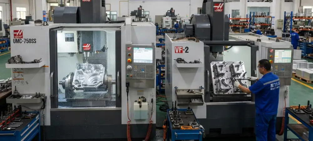
The standard method for machining undercut features on a 3-axis vertical machining center involves reorienting the workpiece across multiple operational setups.
· The Advantage: Lower machine hourly rate on standard 3-axis vertical machining centers.
· The Drawback: Each manual refixturing step introduces datum transfer errors. Cumulative tolerance stack-up across modular soft jaws or vice setups typically adds 0.020 mm to 0.050 mm of positional deviation. Manual handling also increases total labor costs per part.
5-Axis Machining Economics: Standard End Mills vs. Specialty Cutters
Using a 5-axis machining center allows the component to be tilted relative to the spindle axis. Selecting between multiple setups and continuous multi-axis toolpaths is explored in our breakdown of 3-axis vs 5-axis CNC machining capabilities.
· The Kinematic Advantage: Tilting the part transforms a geometric undercut into a direct line-of-sight surface. This allows the use of shorter, rigid standard flat end mills instead of long-reach, flexible keyseat or lollipop cutters.
· Economic Assessment: While 5-axis machine time carries a higher hourly rate, it eliminates multi-setup labor, minimizes datum alignment error, holds true position within 0.005 mm to 0.010 mm, and cuts total cycle time by utilizing higher feeds and speeds on rigid tooling.
Monolithic Machining vs. Fastened Multi-Component Assembly
When an internal undercut requires extreme reach with length to diameter ratios of 8 to 1 or greater, splitting a single monolithic component into two bolt-together subcomponents is often the most cost-effective solution.
A monolithic design requiring custom long-reach tooling carries severe cycle time penalties, high scrap risks, and complex quality assurance routines. In contrast, a split-part design divides the housing into an upper section and a lower base section joined by precision dowel pins and fasteners. Both sections can then be machined open with short, rigid end mills at high material removal rates, lowering total manufacturing costs for production volumes.
Manufacturing Strategy Comparison: Processing Undercut Geometries
|
Evaluation Metric |
3-Axis Multi-Setup (Form Tool) |
5-Axis Continuous (Standard Tool) |
Split-Part Bolted Assembly |
|
Tooling Investment |
High (Custom or semi-standard groovers) |
Lowest (Standard high-speed end mills) |
Lowest (Standard catalog tooling) |
|
Machining Cycle Time |
High (Reduced feed rates, multiple passes) |
Low (Full tool engagement, high MRR) |
Lowest (High-speed open pocketing) |
|
Labor & Setup Time |
High (Manual flips, soft jaw alignments) |
Minimal (Single-setup processing) |
Moderate (Secondary assembly required) |
|
Positional Accuracy |
Plus/minus 0.030 mm (Setup dependent) |
Plus/minus 0.008 mm (High volumetric precision) |
Plus/minus 0.015 mm (Pin location dependent) |
|
Total Cost for Low Volumes (1-50 pcs) |
Moderate |
High (Programming and setup overhead) |
Moderate |
|
Total Cost for High Volumes (500+ pcs) |
High (Cycle time bottleneck) |
Moderate to Low |
Lowest (Optimized production scaling) |
Procurement and DFM Engineering Checklist for Undercut Verification
Before releasing CAD models and 2D engineering drawings for manufacturing, complete this checklist to prevent unexpected quote revisions, tooling surcharges, and production delays.
Pre-Release Undercut DFM Gate
· Tooling Verification: Confirm whether groove width, depth, and corner radius match standard catalog tooling such as DIN 650 or ISO standard keyseat dimensions.
· Entry Clearance Check: Verify that the entry bore or external slot width exceeds the tool head plus neck clearance envelope by at least 1.0 mm.
· Neck Overhang Ratio: Ensure the cutter neck-to-diameter ratio remains below 4 to 1. If greater than 6 to 1, adjust tolerances and surface finish expectations to account for tool deflection.
· Corner Radii Specification: Confirm all internal sharp corners feature an edge radius of at least 0.2 mm.
· Chip Evacuation Route: For blind internal pockets, verify that an axial relief or through-hole is present to vent chips and allow pressurized coolant flow.
· Inspection Datum Strategy: Ensure internal undercut depths and widths reference an accessible external machined datum to facilitate CMM disc-probe calibration.
RFQ Structuring Guide for Dazao Sourcing
When submitting a Request for Quotation to Xiamen Dazao Machinery, including the following details helps our engineering team optimize your quote:
1. Identify Critical Sealing Surfaces: Label specific face requirements such as O-ring gland sealing surfaces requiring Ra 0.8 micrometers so CAM programmers can prioritize targeted surface finishes while running non-critical clearance regions at higher feed rates.
2. Permit Corner Reliefs: Note if cutter runout radius marks or undercut under-sweeps are acceptable on non-functional surfaces.
3. Include 3D STEP and 2D PDF Files: Always provide native 3D CAD data alongside 2D engineering drawings with GD&T callouts. This allows our DFM team to simulate tool interference and verify cutter reach before quoting.
Optimize Your Machined Components with Dazao
Manufacturing complex internal undercuts with tight dimensional tolerances requires specialized multi-axis equipment, practical tooling strategies, and robust quality control systems.
Xiamen Dazao Machinery delivers industrial-grade precision CNC machining services utilizing advanced 3-axis, 4-axis, and simultaneous 5-axis machining centers certified to ISO 9001:2015 and IATF 16949:2016 quality standards. Our technical team conducts detailed DFM evaluations on every incoming project, identifying toolpath clearance challenges, standardizing tooling profiles, and reducing production costs before cutting begins.

FAQs
01.How to eliminate harmonic chatter when milling deep internal keyseat undercuts?
02.Why do blind T-slots frequently cause tool breakage during horizontal slotting?
03.How can internal O-ring grooves be inspected when CMM probes cannot fit through the bore?
04.What causes visible scallop marks when deburring back-side edges with a lollipop cutter?
05.Why do acute dovetail cutters wear out prematurely at the corner tip?
06.When does splitting an undercut housing into two bolted parts become more economical?





