


Over-specifying tolerances is the primary driver of inflated CNC manufacturing budgets. Shifting from a standard machining tolerance of ±0.1 mm under ISO 2768-m to a tight tolerance of ±0.005 mm increases production costs by 250% to 400% through specialized tooling, secondary grinding operations, thermal soaking cycles, and mandatory Coordinate Measuring Machine (CMM) inspection. Applying GD&T for CNC machining with Maximum Material Condition (MMC) instead of linear plus-minus dimensions expands usable manufacturing windows by 57% without compromising mechanical assembly.
Why Over-Tolerancing Escalates CNC Machining Budgets?
Every micrometer specified on an engineering print carries a direct monetary penalty. In production environments, design engineers frequently assign tight tolerances across all drawing features out of liability avoidance or uncertainty regarding exact assembly kinematics. This practice shifts dimensional risk directly onto manufacturing budgets.

The Non-Linear Machining Cost Multiplier
Achieving dimensional accuracy follows an exponential cost curve. Moving from standard roughing passes to high-precision milling requires slower feed rates, shallow depths of cut, specialized micro-grain carbide tooling, climate-controlled machining environments maintained at 20 degrees Celsius, and frequent in-process probing. When sourcing high-precision components through our precision CNC machining services. Understanding the structural factors that influence aluminum CNC machining costs is essential before applying strict tolerances across non-critical clearance geometries.
When a linear dimension moves from commercial ranges down to five micrometers, standard 3-axis CNC vertical machining centers can no longer maintain reliable process capability. The part must be routed through secondary operations, such as precision cylindrical grinding, jig boring, or high-precision Wire Electrical Discharge Machining.
|
Tolerance Class |
Typical Linear Tolerance Range |
Required Machining / Finishing Process |
Relative Cost Index |
Primary Cost Drivers |
|
Commercial (Standard) |
±0.100 mm to ±0.200 mm |
Standard 3-Axis / 5-Axis CNC Milling & Turning |
1.0x (Baseline) |
Standard feeds and speeds, batch sampling with manual micrometers |
|
Precision |
±0.025 mm to ±0.050 mm |
High-End CNC VMC, Finishing Toolpaths, Reaming |
1.6x - 2.2x |
Dedicated finish tooling, slower feed rates, standard CMM verification |
|
High Precision |
±0.010 mm to ±0.020 mm |
Jig Grinding, Hard Turning, Slow-Speed Wire EDM |
2.8x - 3.8x |
Thermal stabilization cycles, in-machine tool setters, bore gauging |
|
Ultra-Tight (Micro) |
Under ±0.005 mm |
Lapping, Honing, Multi-Pass Precision Grinding |
4.5x - 8.0x+ |
High scrap rates, full CMM inspection in cleanrooms |
To control tight tolerance CNC machining cost, the initial tolerance design phase must distinguish between functional mating interfaces and non-critical clearing geometries.
Production Reality: The 35% Scrap Rate Non-Functional Callout
At Dazao Machinery, an optical equipment customer submitted an enclosure drawing featuring 16 clearance through-holes for M4 socket head cap screws. The drawing title block applied a blanket tolerance of ±0.010 mm across all features without functional GD&T callouts.
Because standard twist drilling drifts depending on tool entry dynamics and material grain structure in standard industrial aluminum CNC machining processes, meeting this specification forced the shop floor to spot-drill, rough-drill undersized, end-mill to location, and finish with custom reamers.
During the initial batch of 200 units, tool wear on the reamer caused 70 parts to fall out of the tight specification band, resulting in a 35% scrap rate. After engineering review, Dazao confirmed the holes were simply clearance features. Reviewing fundamental precision CNC hole making and drilling parameters allowed the customer to update the drawing to an ISO standard clearance hole of 4.5 mm with a standard tenth of a millimeter tolerance. This change eliminated the reaming pass, reduced cycle time by 4 minutes per part, and dropped the scrap rate to 0%.
ISO 2768 Standards and Title Block General Tolerances: Eliminating Drawing Ambiguities
A standard machining tolerance engineering drawing relies on title block general tolerances to govern unnoted geometric and linear dimensions. Specifying a recognized international standard prevents drawing clutter and defines the baseline quality level expected from the manufacturing facility.
ISO 2768-1 and ISO 2768-2 Breakdown
ISO 2768 is divided into two distinct sections:
· ISO 2768-1: Covers linear and angular dimensions, categorized into tolerance classes: Fine (f), Medium (m), Coarse (c), and Very Coarse (v).
· ISO 2768-2: Covers geometrical tolerances including flatness, straightness, cylindricity, and symmetry, broken into classes H, K, and L.
For precision CNC milling and turning at Dazao, specifying ISO 2768 CNC tolerance class mK represents the natural economic capability of modern machining centers. Evaluating the capability differences between 3-axis and 5-axis CNC setups confirms that setting general tolerances to class f across large frames forces unnecessary cycle slowdowns, thermal stabilization pauses, and frequent tool offset adjustments. Designers can benchmark these boundaries against standard aluminum machining tolerance bands.
CNC Tolerance Chart (ISO 2768-1 Linear Dimensions)
|
Nominal Dimension Range (mm) |
Fine (f) |
Medium (m) |
Coarse (c) |
Very Coarse (v) |
|
0.5 to 3 |
±0.05 mm |
±0.10 mm |
±0.20 mm |
Not Applicable |
|
Over 3 to 6 |
±0.05 mm |
±0.10 mm |
±0.30 mm |
±0.50 mm |
|
Over 6 to 30 |
±0.10 mm |
±0.20 mm |
±0.50 mm |
±1.00 mm |
|
Over 30 to 120 |
±0.15 mm |
±0.30 mm |
±0.80 mm |
±1.50 mm |
|
Over 120 to 400 |
±0.20 mm |
±0.50 mm |
±1.20 mm |
±2.50 mm |
|
Over 400 to 1000 |
±0.30 mm |
±0.80 mm |
±2.00 mm |
±4.00 mm |
|
Over 1000 to 2000 |
±0.50 mm |
±1.20 mm |
±3.00 mm |
±6.00 mm |
This CNC tolerance chart defines the expected deviation based on nominal size, ensuring that larger physical dimensions receive proportionate manufacturing allowances.
The Title Block Ambiguity Trap and Quoting Defense Buffers
A common issue encountered during quotation analysis is drawing ambiguity caused by conflicting general notes. A drawing title block will state General Tolerance: ISO 2768-mK, while a note in the drawing field states that unless otherwise specified, all dimensions must be held to ±0.05 mm.
On a 250 mm overall length feature, ISO 2768-m permits a deviation of half a millimeter, which is easily achieved through a single high-speed pass. However, the restrictive drawing note forces permissible deviation down to a twentieth of a millimeter, requiring multiple finish passes, thermal normalization, and full CMM verification.
When this contradiction exists, manufacturing engineers must quote based on the tighter requirement to avoid incoming quality control rejections. As a result, cycle times are calculated using conservative finishing toolpaths, and estimators add a 30% to 45% risk buffer to the unit price. Applying clear engineering guidelines for aluminum CNC part design and defining general tolerance title block machining rules eliminates these pricing buffers.
Practical GD&T for CNC Machining: Expanding Manufacturing Windows with True Position
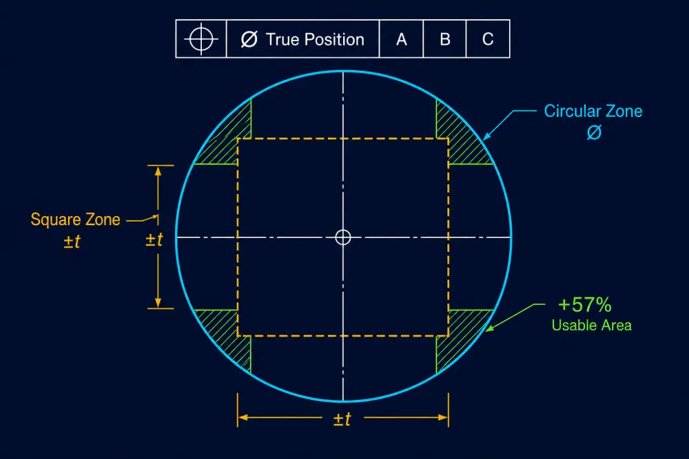
Coordinate dimensioning with plus-minus tolerances creates square or rectangular tolerance zones. This traditional methodology misrepresents machine kinematics and artificially restricts the allowable variation of mating features. Implementing geometric dimensioning and tolerancing provides a more functional approach.
Coordinate Tolerancing vs. True Position
When a hole location is defined using plus-minus coordinate dimensions, the resulting permissible deviation forms a square boundary. The greatest allowable displacement occurs at the extreme diagonal corners of this square.
If the mating part functions properly at that extreme corner displacement, a cylindrical tolerance zone can be defined using that diagonal distance as the allowable diameter. Replacing the square boundary with a cylindrical zone increases the allowable manufacturing area by 57 percent.
Specifying true position tolerance CNC machined parts with a circular boundary gives the machine operator substantial additional process margin without altering the functional fit of mating fasteners or dowels. This is particularly valuable when aligning clearance holes with standard thread design rules for machined enclosures.
Maximum Material Condition (MMC) and Bonus Tolerance
When a position tolerance is applied with the Maximum Material Condition modifier, the specified positional tolerance applies only when the feature of size is at its maximum material boundary, which corresponds to the smallest permissible hole diameter or largest permissible shaft diameter.
Bonus tolerance is gained as the actual manufactured hole diameter becomes larger than the minimum specification limit. This extra allowable positional variation prevents structurally sound components from being scrapped due to slight drill walk, because the enlarged hole volume easily accommodates the mating pin.
Datum Reference Frame Alignment with CNC Fixturing
A frequent failure mode in drawing creation is designating flexible, non-machined, or inaccessible features as primary datums. CNC fixtures locate components using the 3-2-1 locating principle:
1. Primary Datum A: Must be a stable, fully machined planar surface establishing 3 contact points, constraining pitch, roll, and vertical translation.
2. Secondary Datum B: A perpendicular machined edge or precision bore establishing 2 contact points, constraining yaw and horizontal translation.
3. Tertiary Datum C: A final perpendicular face or stop pin establishing 1 contact point, constraining the remaining linear degree of freedom.
Assigning Datum A to a deep cavity floor machined during a secondary setup while using raw stock edges from the first setup as Datums B and C forces split fixturing. This introduces setup relocation errors that consume the tolerance budget. Consulting deep pocket milling constraints and tool reach limitations ensures datums align with physical machining setups.
Engineering Shaft and Bore Fits: Press Fit Calculations and Tool Deflection Limits
Specifying cylindrical fits requires matching the dimensional boundaries of mating shafts and holes to their mechanical loads, operating speeds, and environmental temperatures.

The ISO 286 Fit System in Precision Machining
The ISO fit system pairs fundamental tolerance grades with fundamental deviations:
· Clearance Fits (such as H7/g6 or H7/h6): Guarantee positive clearance for free rotation or sliding movement.
· Transition Fits (such as H7/k6 or H7/n6): Provide accurate location where components require light force for assembly.
· Interference Fits (such as H7/p6 or H7/s6): Provide rigid retention and torque transmission without keys or set screws.
|
Fit Classification |
ISO Hole/Shaft Pair |
Target Application |
Machining Process Capability |
Typical Radial Clearance / Interference |
|
Loose Running |
H11 / c11 |
Commercial pivots, linkage pins |
Standard Drilling & Turning |
Positive clearance up to 0.150 mm |
|
Precision Sliding |
H7 / g6 |
Machine tool spindles, sliding gears |
Precision Boring, Reaming, Grinding |
Positive clearance from 0.005 mm to 0.020 mm |
|
Location Transition |
H7 / k6 |
Locating dowels, gear hub centering |
Precision Boring & Micro-Turning |
Slight gap to light tap fit |
|
Light Press Fit |
H7 / p6 |
Ball bearing retention in housings |
CNC Single-Point Finish Boring |
Interference from 0.005 mm to 0.025 mm |
|
Heavy Drive Fit |
H7 / s6 |
Permanent sleeve bushings, drive hubs |
Jig Boring, Precision Grinding |
Heavy interference up to 0.045 mm |
Engineering a Reliable Press Fit Tolerance Shaft Bore
When engineering a press fit tolerance shaft bore, designers must account for cutting tool deflection during internal boring passes. Tool deflection increases exponentially with boring bar overhang and decreases as the bar diameter increases.
As the depth-to-diameter ratio of an internal bore exceeds four to one, cutting forces push the boring bar away from the cut surface. This creates a natural taper where the mouth of the bore meets the target diameter, while the bottom of the bore remains undersized.
To prevent binding during assembly:
1. Design relief undercuts: Incorporate internal relief grooves at the bottom of blind bearing bores, utilizing standard internal groove and undercut machining methods to eliminate tool dwell at the base.
2. Specify lead-in chamfers: Design an entry lead-in angle of 15 to 20 degrees with an axial depth of at least one millimeter to prevent galling during mechanical press-fitting.
3. Control depth-to-diameter ratios: Limit tight-tolerance bearing bores to a depth-to-diameter ratio below three to one to enable rigid single-point boring tools to operate without chatter.
Material Physics and Surface Finishing: Managing Stress Relief and Plating Growth
Achieving consistent dimensional accuracy requires evaluating the physical metallurgy of the workpiece and the chemical dimensions added during surface treatments.
Thin Walls and Residual Stress Warpage
Thin-walled aluminum housings under one millimeter and thin cross-section rings deform under clamping forces and cutting loads. In structural alloys, internal residual stresses from raw material processing release during bulk material removal, causing asymmetric warpage.
Maintaining dimensional stability on thin geometries requires respecting critical wall thickness thresholds in precision milling. The standard process protocol involves roughing the majority of the material stock, unfastening the part to allow internal stress relaxation, and re-clamping under light torque for final finishing passes.
|
Material Grade |
Thermal Expansion Coefficient |
Elastic Modulus |
Practical CNC Tolerance Limit |
|
Al6061-T651 |
23.2 micrometers per meter-Kelvin |
68.9 GPa |
±0.010 mm |
|
Al7075-T651 |
23.6 micrometers per meter-Kelvin |
71.0 GPa |
±0.008 mm |
|
Stainless Steel 304 |
17.2 micrometers per meter-Kelvin |
193.0 GPa |
±0.012 mm |
|
Stainless Steel 316L |
16.0 micrometers per meter-Kelvin |
193.0 GPa |
±0.012 mm |
|
Titanium Ti-6Al-4V |
8.6 micrometers per meter-Kelvin |
113.8 GPa |
±0.010 mm |
|
Polyoxymethylene (POM) |
110.0 micrometers per meter-Kelvin |
2.8 GPa |
±0.050 mm |
|
PEEK (Virgin) |
47.0 micrometers per meter-Kelvin |
3.8 GPa |
±0.030 mm |
Post-Treatment Dimensional Drift: Anodizing Growth
A frequent root cause of drawing non-conformance in CNC tolerance design is failing to account for surface finish build-up. Anodizing converts base aluminum into an aluminum oxide layer where approximately half of the coating penetrates the substrate and half builds outward from the original surface. When adhering to strict precision anodizing and surface plating standards, dimensional growth must be calculated directly into the pre-machined toolpaths.
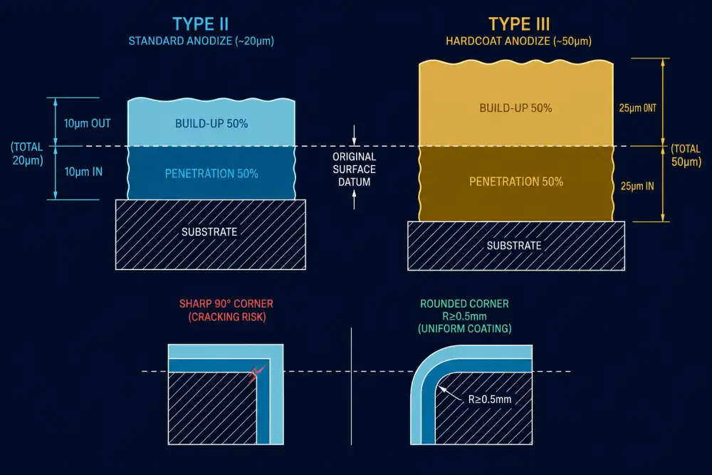
For standard sulfuric anodizing, outward surface growth reduces internal bore diameters by approximately one to two hundredths of a millimeter. For hardcoat anodizing, outward growth reduces internal bore diameters by up to five hundredths of a millimeter.
If an internal bearing bore requires a precision fit after hardcoat anodizing, machining the bore to nominal size prior to plating results in an undersized, rejected part. Engineering drawings must explicitly state whether dimensions apply before coating or after coating so that CNC machinists can pre-bore oversize.
Multi-Part Tolerance Stack-Up Analysis: Worst-Case vs. Statistical RSS Models
When multiple precision CNC components assemble into a sub-system, individual part variations accumulate. Calculating this variation during design prevents assembly interference.
Worst-Case vs. Root Sum Square (RSS) Analysis
Worst-case tolerance stack analysis assumes that every manufactured component in the assembly chain is produced at its extreme physical limit simultaneously. The total worst-case variation equals the direct linear addition of all individual tolerance bands.
Statistical Root Sum Square analysis assumes that component manufacturing deviations follow a normal Gaussian distribution centered at nominal dimensions. The total statistical stack variation is determined by combining the squared variations of individual components.
In a five-part mechanical assembly where each component has an individual tolerance of ±0.040 mm, the worst-case cumulative variation reaches ±0.200 mm. In contrast, the statistical cumulative variation remains within approximately ±0.090 mm. The statistical model demonstrates that realistic assembly variation is less than half of the theoretical worst-case maximum.
Use worst-case analysis for low-volume production under 50 units, short kinematic links with three or fewer parts, and safety-critical medical or aerospace systems. Use statistical analysis for high-volume serial production where process capability is actively verified through statistical process control. Addressing tolerance stack-up in CNC machining early in the CAD stage protects both assembly function and budget.
Dazao Case Study: Resolving the Optical Housing Stack Error
A high-resolution LiDAR sensor enclosure manufactured at Dazao contained five stacked CNC aluminum retaining rings, spacers, and lens seats. Every individual component passed incoming quality control against its individual linear drawing tolerance of ±0.035 mm.
However, during final assembly at the customer facility, the objective lens failed to reach focus due to an axial stack-up displacement error of nearly two-tenths of a millimeter.
In the original assembly design, five separate components were stacked sequentially, consisting of a base flange, two shims, a lens seat, and a lock ring. The cumulative axial variation across the five interfaces created direct interference with the focal adjustment mechanism.
Dazao value-engineering resolved the issue by redesigning the sub-assembly into a single monolithic five-axis milled housing that combined the base flange, first shim, and lens seat. Machining these features from a single datum reference in one setup reduced the finished axial variation to ±0.020 mm while cutting total production cost by 22%.
Metrology Disconnects: Resolving CMM Inspection Reports vs. Physical Assembly Binding
A component that measures within drawing tolerances on a CMM inspection report can still bind or fail during physical assembly due to point-sampling limitations and form errors.

CMM Probe Point Sampling vs. Functional Form Errors
Standard discrete-point CMM routines often measure an internal bore by recording four to eight touch points. The software then applies an averaging algorithm to construct a theoretical circle.
If three-jaw chuck clamping forces deform a thin-walled sleeve during turning, the finished bore will exhibit a three-lobed form defect. A standard discrete CMM inspection may touch intermediate zones and calculate an acceptable diameter for a 20 mm nominal hole. However, when a precision cylindrical gauge pin is inserted, the lobed interference peaks prevent entry.
To eliminate this inspection disconnect:
· Specify continuous scanning CMM routines with high point densities exceeding 500 points per revolution, or add explicit Cylindricity and Roundness callouts on precision bores.
· Specify functional gauging requirements directly in drawing notes, stating that features must pass full-length Class X Go and No-Go plug gauges at 20 degrees Celsius.
Thermal Expansion in Precision Metrology
Machining workshops frequently operate between 24 and 30 degrees Celsius, while calibrated metrology laboratories are maintained strictly at 20 degrees Celsius.
Thermal contraction occurs when a warm aluminum component enters a cooled metrology laboratory. For a 300 mm aluminum structural plate, an eight-degree temperature drop from a warm shop floor to a cooled quality laboratory results in more than five hundredths of a millimeter of dimensional shrinkage.
If a tight tolerance of ±0.025 mm is verified immediately on the machine tool bed without a thermal soaking cycle, the part will measure out of specification during final inspection. Dazao quality protocols rely on rigorous temperature-controlled metrology and CMM inspection workflows, requiring a 4-hour thermal stabilization period in the metrology cleanroom for all precision components prior to final inspection reporting.
Dazao DFM Matrix: Actionable Tolerance Allocation and Drawing Review Checklist
Balancing mechanical performance with production economy requires categorizing every drawing dimension into functional tiers before finalizing prints.
|
Feature Category |
Target Tolerance Band |
Applicable Geometry Features |
Cost Multiplier |
|
Non-Critical Clearance |
ISO 2768-mK (±0.20 mm to ±0.50 mm) |
Outer chamfers, clearance pockets, cosmetic reliefs, wire paths |
1.0x (Baseline) |
|
Fastener Location |
Positional Ø0.25 mm at MMC |
Clearance through-holes, bolt circles, mounting patterns |
1.1x |
|
Sliding / Locating Fits |
ISO H7 / h6 (±0.010 mm to ±0.015 mm) |
Dowel alignment pins, precision slides, bronze sleeve bushings |
1.5x - 1.8x |
|
Dynamic Press Fit / Sealing |
ISO H6 / p5 (±0.005 mm to ±0.008 mm) |
Spindle bearing bores, hydraulic piston sleeves, dynamic seal lands |
2.5x - 4.0x |
Pre-Release DFM Tolerance Checklist for Engineers
Before releasing a drawing for production or formal quotation, review the following five criteria:
1. Title Block Cleanliness: Is the general tolerance set to ISO 2768-mK, and have conflicting arbitrary drawing notes been removed?
2. GD&T Datum Alignment: Are Datums A, B, and C assigned to accessible, fully machined planar faces that match the physical 3-2-1 CNC clamping setup?
3. True Position with MMC: Have rectangular coordinate tolerances on hole patterns been converted to True Position with Maximum Material Condition callouts?
4. Coating Growth Allowance: Does the drawing define whether critical bore and shaft dimensions apply before coating or after coating?
5. Internal Pocket Geometry: Have internal cavity corner radii been specified with reference to managing internal corner radii to control machining cost to eliminate corner chatter and allow standard tooling passes?

FAQs
01.Why does a CNC quote jump drastically when changing from ±0.1 mm to ±0.01 mm?
02.How do engineers compensate for anodizing growth on tight bearing bores?
03.Why does a pin gauge bind in a hole that passed CMM inspection?
04.What should take precedence: title block tolerances or drawing technical notes?
05.When should Maximum Material Condition (MMC) be applied to true position callouts?
06.How can deep bore taper caused by tool deflection be prevented?





