


Effective weight reduction design for machined parts requires prioritizing stiffness and dynamic stability over raw mass removal. Cutting pockets without respecting tool engagement angles, stress release dynamics, or natural vibration frequencies creates out-of-tolerance scrap. Machining stable, lightweight CNC machined parts demands structural ribs with calibrated aspect ratios, corner radii oversized relative to tool diameter, and conversion of organic topology meshes into prismatic 2.5D toolpaths.
CNC Weight Reduction: Pockets, Ribs, Topology Optimization & Lightweight Design
Achieving structural weight reduction in CNC machining is an engineering discipline centered on material distribution rather than arbitrary wall thinning. In mechanical systems across aerospace, robotics, and performance automotive platforms, removing mass without maintaining structural integrity leads directly to functional failure. True CNC lightweight parts design maintains stiffness, fatigue resistance, and geometric precision across operational load paths. When structural material is removed indiscriminately, parts suffer catastrophic elastic deflection under nominal working loads, lose bearing bore concentricity, and introduce resonant vibration into dynamic assemblies.
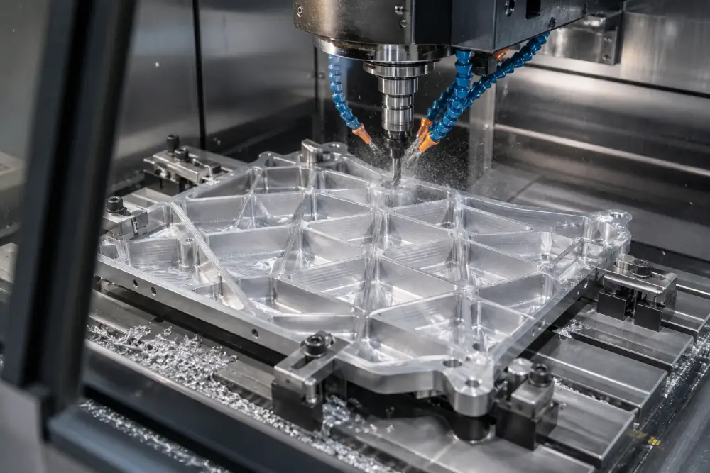
Dazao handles hundreds of lightweight aluminum part design projects annually where CAD models show exceptional theoretical strength-to-weight ratios in finite element simulations, yet fail entirely during physical machining. The primary reason is that standard CAD/CAM modeling rarely accounts for clamping forces, tool push-off, cutter chatter, and the release of internal material stress. Practical lightweight cnc design bridges finite element load paths with practical cutting tool dynamics, fixturing physics, and post-machining dimensional stability.
The Engineering Mechanics of Weight Reduction in CNC Machining
Eliminating mass from high-performance components requires a clear distinction between structural yield strength and flexural rigidity. While tensile strength prevents permanent material failure under peak static load, flexural rigidity dictates how much a component will bend, twist, or flutter when dynamic forces are applied.
Load Path Mapping vs. Geometric Mass Removal
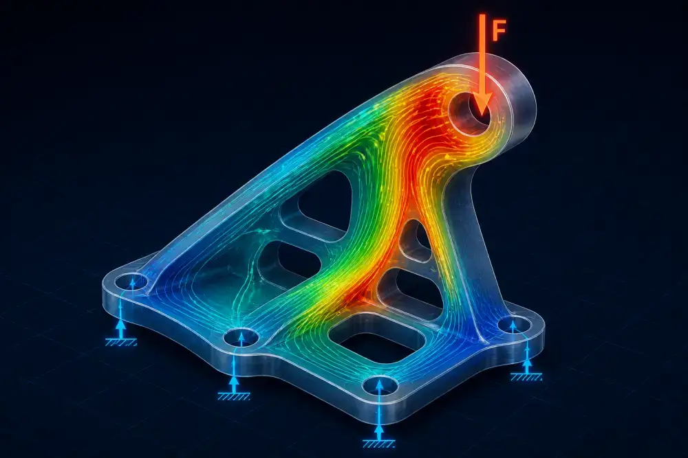
When evaluating how to reduce part weight without losing strength, engineers must map the primary, secondary, and torsional load paths through the structure:
· Primary Load Paths: Sections of solid material that transfer force directly between mounting points, bearing journals, and actuator interfaces. These areas must maintain continuous cross-sections without abrupt wall transitions.
· Low-Stress Zones: Neutral bending axes, central plate sections, and exterior non-locating perimeters. These zones are prime candidates for pocket milling, web thinning, and material relief.
· Interface Integrity: Bolt flanges, dowel pin locations, and press-fit bores require dedicated material bosses. Pocketing directly up to a bolt hole risks localized thread pull-out and distortion during assembly torquing.
Structural Deflection and Section Modulus
The resistance of a machined component to bending is governed by its area moment of inertia. Reducing a solid 20mm aluminum plate to a 4mm flat plate cuts weight by 80%, but reduces bending stiffness by over 98%.
To preserve the strength to weight ratio in mechanical design, the solid mass must be replaced with engineered geometric forms:
· I-beam configurations that place material as far as possible from the neutral bending axis.
· Box-section pockets with supported vertical webs to resist diagonal shearing loads.
· Continuous perimeters that maintain outer frame rigidity while coring out internal material volume.
Pocketing and Rib Design Rules for Lightweight CNC Parts
Machining deep cavities and tall walls requires strict adherence to tooling geometry, spindle horsepower limits, and chip evacuation physics. The geometry of pockets and ribs dictates cycle time, surface finish, and tool wear.
Pocket Geometry: Depth-to-Width Ratios and Tool Deflection
Deep pocketing requires long-reach endmills. Tool deflection increases with the cube of the tool overhang length. When executing CNC pocketing for weight reduction, applying standard rules from our detailed CNC pocket design guide ensures that tool deflection remains negligible during material clearing.
Key geometric parameters include:
· Standard Pocket Depth: Keep maximum pocket depth under 3 to 4 times the cutter diameter to avoid tool chatter and excessive wall taper.
· Deep Cavity Relief: If pocket depth must exceed 5 times the cutter diameter, design stepped pocket walls or draft angles of 1 to 2 degrees to allow larger, more rigid tool shanks to clear upper pocket edges.
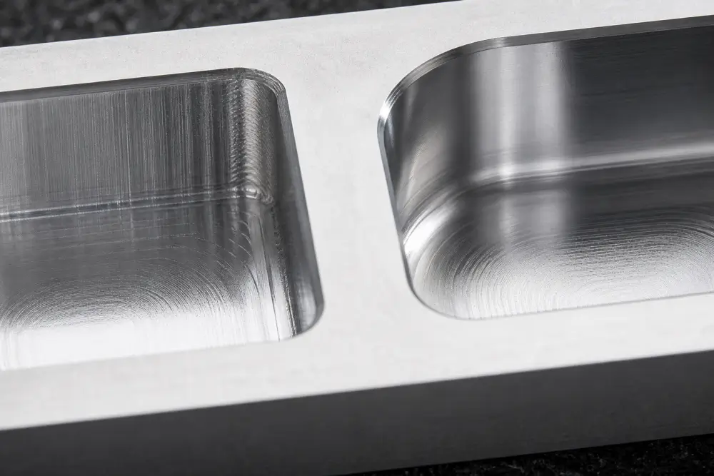
· Bottom Corner Radii: Always specify a bottom floor radius of at least 0.5mm to 1.5mm. Sharp 90-degree internal floor transitions create high stress concentrations and force machinists to run flat endmills at reduced feed rates.
The 1.15x Internal Corner Radius Rule
A frequent design error in weight reduction design for machined parts is specifying inside corner radii identical to standard tool radii, such as a 3.0mm inside radius designed for a 6.0mm endmill.
When a 6.0mm tool reaches a 3.0mm corner, the cutter engagement angle jumps instantaneously from 90 degrees to 180 degrees. This sudden increase in tool load causes tool deflection, poor surface finish, and high risk of tool breakage. Specifying internal radii equal to the cutter radius forces spindle deceleration, whereas referencing our corner radius machining cost breakdown demonstrates the feed rate benefits of oversized corners.
To maintain continuous high-speed tool motion without deceleration:
· Set inside corner radii to at least 1.15 to 1.25 times the cutter radius, such as specifying an inside corner radius of 3.5mm to 4.0mm for a 6.0mm tool.
· Allow the CAM toolpath to use dynamic trochoidal peeling loops in corners rather than full-width slotting stops.
Rib Architecture: Isogrid vs. Orthogrid vs. Triangular Patterns
Structural ribs convert thin-wall plates into rigid lightweight structures. Selecting the right rib pattern depends on directional loading and machine capability. For unsupported rib heights, engineers should review our machining guide on CNC wall thickness to establish chatter-free baseline dimensions:
|
Structural Rib Type |
Bending Rigidity |
Torsional Rigidity |
Machining Complexity |
Typical Application |
|
Triangular (Isogrid) |
Exceptionally High |
High (Multi-directional) |
High (3-axis / 5-axis continuous) |
CNC machined aerospace lightweight parts, satellite panels |
|
Rectangular (Orthogrid) |
High (0°/90° axes only) |
Moderate |
Moderate (Fast clearing paths) |
Structural chassis, electronic enclosures |
|
Diagonal Cross-Rib |
Moderate to High |
High (Shear resistant) |
Low to Moderate |
Robotic arms, linear slide brackets |
|
Unidirectional Ribs |
High (Single axis) |
Low |
Low |
Heat sinks, structural guide rails |
Rib Height, Thickness, and Base Blending Rules
To avoid rib buckling and manufacturing vibration:
· Rib Aspect Ratio: Keep rib height under 6 times rib thickness for Al6061-T6 and under 8 times for Al7075-T651. Taller ribs require custom step-down tooling and slow machining feeds.
· Floor-to-Rib Thickness Ratio: The base floor thickness should be between 0.8 and 1.2 times the rib thickness. Mismatched thicknesses create thermal expansion discrepancies and localized stress concentrations during anodizing.
· Floor Blend Radii: Add a continuous 1.0mm to 2.0mm blend radius at the junction where ribs meet the pocket floor to distribute bending moments effectively.
Three Critical Shop-Floor Failure Points in Aggressive CNC Weight Reduction
Most engineering design literature covers pocket calculations and theoretical FEA models, but ignores physical manufacturing mechanics. At Dazao, our production floor regularly encounters three failure mechanisms that cause severe dimensional scrap during lightweighting operations.
Failure Point 1: Bulk Material Stress Release and Part Warpage
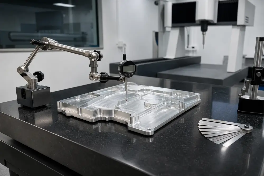
Standard wrought aluminum plates, such as 6061-T6 or 7075-T6, retain substantial residual stresses from initial rolling, quenching, and artificial aging processes. These internal stresses are balanced throughout the bulk stock volume. Controlling warp during aggressive material removal requires following the thermal and stress relief protocols in our aluminum CNC machining manufacturing guide.
When aggressive pocketing removes 70% to 90% of the raw stock volume from one side of a billet:
· The internal stress equilibrium is destroyed. The remaining thin bottom skin contracts or expands unevenly.
· The part warps into a curved shape upon unclamping from the vise, destroying flatness tolerances, often exceeding 0.5mm across a 200mm span.
· Post-machining surface treatments like Type II or Type III sulfuric anodizing introduce additional thermal stress, worsening the distortion.
Dazao Manufacturing Solution:
· Always specify stress-relieved plate stock with stretched tempers like T651, which undergoes a mechanical stretch after heat treatment to neutralize residual stress.
· Implement balanced two-sided roughing: rough mill 50% of the top pockets, flip the part to rough mill the bottom side, release clamping torque to allow stress relaxation, and execute final finish passes at light depths of cut.
Failure Point 2: Resonant Chatter Cliffs and Clamping Deflection on Thin Floors
When pocket floors are machined below 1.5mm thickness, the local natural frequency of the unsupported sheet metal drops into the operating frequency range of typical high-speed CNC spindles.
· The Chatter Cliff: As the cutter passes over the center of a wide, thin floor, the floor deflects away from the cutting edge and snaps back elastically. This harmonic vibration leaves loud chatter marks, degrades surface finish from Ra 0.8 to over Ra 3.2, and chips carbide cutting edges.
· Vacuum Fixture Deflection: Thin pocket floors deflect downward under strong vacuum table suction or mechanical toe-clamping pressure. When the cutter finishes a pass on the deflected floor and the clamp is released, the floor springs back upward, making the center significantly thinner than the edges.
Dazao Manufacturing Solution:
· Maintain a minimum floor thickness of 1.2mm to 1.5mm for structural aluminum components unless secondary backing dampening is engineered into the fixture.
· Utilize dedicated polyurethane or paraffin wax support fixtures beneath thin-floor pockets to provide physical backing dampening during high-speed finish passes.
Failure Point 3: The CAM Translation Fallacy of Generative and Topology-Optimized Models
Generative design and topology optimization algorithms generate organic, non-prismatic structural skeletons with continuously varying 3D surfaces. Exporting raw faceted STL files directly to CAM programming causes an exponential spike in machining costs:
· Micro-Rest Machining Penalties: Organic 3D fillets require 5-axis ball-nose or bull-nose endmills running micro-stepover toolpaths to achieve acceptable surface finishes. A pocket that takes 45 seconds to clear with a flat endmill can take 35 minutes of 3D surfacing to clear with a ball-nose tool.
· Tool Shank Collisions: Algorithm-generated undercuts and variable drafts often require custom, ultra-long-reach tooling that deflects under minimal cutting pressure, requiring slow feed rates and driving up machining hours.
· Economic Trade-Off: Spending 4 additional machine hours to save 35 grams of aluminum on a bracket increases component cost by 300% without delivering functional performance improvements.
Practical Engineering Execution of Topology Optimization for CNC Machining
Topology optimization is a mathematical approach that redistributes material within a designated design space based on defined loads, boundary conditions, and performance constraints. However, running an algorithmic solver without manufacturing constraints creates organic geometries that cannot be economically cut with subtractive machine tools.
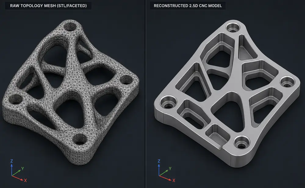
Converting Organic Meshes into Prismatic Machinable Features
To make topology optimization for CNC machining viable, the raw faceted STL output from FEA software must serve purely as a structural guide rather than a final machining model.
The standard engineering workflow requires:
· Boundary Extraction: Import the optimized density mesh into parametric CAD software as a reference body.
· Prismatic Reconstruction: Re-model organic struts into planar pocket walls, standard draft angles, and uniform-thickness webs that match standard endmill diameters.
· Standardized Tool Paths: Ensure all internal cavities can be cleared using standard flat-bottom carbide endmills, reserving 5-axis ball-nose surfacing only for unavoidable aerodynamic outer surfaces.
Embedding Subtractive Milling Constraints in FEA Solvers
Modern topology solvers permit manufacturing constraints directly in the optimization setup. Configuring these parameters prevents algorithms from generating impossible geometries:
· Milling Direction Constraints: Set single-axis or two-axis parting constraints to prevent internal hollows and undercuts that cutting tools cannot reach.
· Minimum Member Size: Enforce a minimum wall thickness parameter, such as not less than 2.0mm, to prevent the generation of micro-struts that vibrate and fracture during CNC milling.
· Overhang and Draft Angle Limits: Establish a draw direction constraint of 1 to 3 degrees to ensure cutting tools maintain clearance along deep pocket walls without tool shank rubbing.
Preserved Non-Design Regions and Interface Integrity
Certain features must be excluded from mass removal to maintain mechanical functionality. In FEA software, these are designated as Preserved Regions:
· Bearing Housings and Bushing Bores: Maintain solid, thick-walled cylindrical bosses around press-fit journals to prevent hoop stress deformation during assembly.
· Threaded Fastener Interfaces: Ensure a minimum solid material boundary equal to 1.5 times the nominal thread diameter around tapped holes to resist preload tensile forces.
· Precision Dowel Pin Locations: Keep mounting interfaces rigid and planar to prevent geometric tolerance stacking across mating sub-assemblies.
Material Selection and Strength-to-Weight Optimization
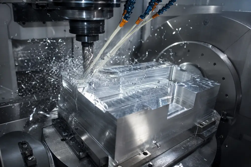
Selecting the correct alloy is fundamental to achieving high performance in lightweight CNC machined parts. Substituting heavier structural metals with high-strength aluminum or titanium requires balancing tensile strength, fatigue limits, stiffness, and machinability.
Mechanical Properties and Machinability Comparison
The following data reflects structural materials commonly processed for precision lightweight assemblies:
|
Material Grade |
Density (g/cm³) |
Tensile Yield Strength (MPa) |
Modulus of Elasticity (GPa) |
Specific Strength (kN·m/kg) |
Machinability Index (% of Al6061) |
Raw Material Cost Factor |
|
Al6061-T651 |
2.70 |
276 |
68.9 |
102 |
100% (Baseline) |
1.0x |
|
Al7075-T651 |
2.81 |
503 |
71.7 |
179 |
80% |
1.8x |
|
Al2024-T351 |
2.78 |
324 |
73.1 |
117 |
75% |
1.5x |
|
Ti-6Al-4V (Gr. 5) |
4.43 |
880 |
113.8 |
198 |
20% |
6.5x |
|
AISI 4140 Steel |
7.85 |
655 |
205.0 |
83 |
45% |
0.8x |
|
AZ31B Magnesium |
1.77 |
200 |
45.0 |
113 |
125% |
2.4x |
The Modulus Trap in Lightweight Aluminum Part Design
A frequent engineering mistake is substituting structural steel with high-strength aluminum based solely on yield strength. While 7075-T651 approaches the yield strength of mild steel, its modulus of elasticity is approximately one-third that of steel (71.7 GPa vs. 205 GPa). When calculating deflection risk during steel-to-aluminum transitions, consult our aluminum CNC machining design manual for geometric moment calculations.
Under identical bending forces, an aluminum component with identical dimensions will deflect three times more than a steel component. To maintain identical flexural stiffness when switching from steel to aluminum, the section height of the aluminum part must increase by approximately 44%, even though total component mass will still decrease by roughly 50%.
Fastener Retention in Thin-Wall Lightweight Assemblies
Cutting weight from structural frames introduces major risks at bolted connections. Direct threading into thin aluminum walls leads to thread stripping under standard torque specifications.
To preserve assembly integrity without adding unnecessary bulk:
· Helical Wire Inserts (Helicoil): Ideal for dynamic components requiring high pull-out resistance with minimal weight penalty. Requires an outer boss diameter of at least 2.0 times the nominal bolt diameter.
· Key-Locking Inserts (Keensert): Best for heavy-vibration applications in aerospace brackets. Keenserts require thicker surrounding wall sections to accommodate the larger external insert body.
· Engagement Depth Ratios: Maintain a thread engagement depth of at least 1.5 times the bolt diameter in 6061-T6, and at least 2.0 times the bolt diameter in magnesium alloys.
Economic Inflection Points: Machining Cost vs. Weight Reduction
Aggressive lightweighting follows an exponential manufacturing cost curve. Understanding this relationship prevents over-engineering and keeps production runs commercially viable.
The Cost-to-Weight Curve in CNC Machining
Balancing mass removal percentages against cycle times is outlined in our aluminum CNC machining cost analysis. Mass removal exhibits three distinct economic stages:
· 0% to 50% Mass Removal: Linear cost increase. Pocket depths are shallow, tool aspect ratios remain below 3 to 1, and standard roughing parameters apply.
· 50% to 75% Mass Removal: Moderate cost increase. Requires specialized stress-relieved stock (T651), flipped-part roughing cycles, and intermediate floor finishing passes.
· 75% to 90%+ Mass Removal: Exponential cost explosion. Machining cycle times jump significantly due to micro-stepover toolpaths, custom vibration-dampened tooling, custom vacuum fixtures, and high scrap rates caused by warpage.
Machine Selection: 3-Axis Multiple Setups vs. 5-Axis Continuous Milling
Complex pocketed components often feature weight-relief pockets on multiple faces. Evaluating whether to run multi-side pockets on standard mills or continuous multi-axis centers is detailed in our 3-axis vs 5-axis CNC machining comparison:
· 3-Axis Approach: Requires multiple soft-jaw setups or modular fixtures to machine pockets across 4 to 6 orientations. Setup errors compound tolerance stacks, and loading time extends overall production schedules.
· 5-Axis Simultaneous Approach: Allows continuous pocketing and 3D web machining in a single clamping setup. Positional accuracy across bearing journals is maintained within tight limits, while total cycle time drops by 40% on complex parts despite higher hourly machine rates.
Surface Finishing Risks on Thin-Wall Structures
Post-machining processes can distort or damage thin-walled lightweight parts. Maintaining critical bearing fits after anodizing requires strict adherence to our aluminum machining tolerances standard:
· Abrasive Bead Blasting: High-pressure media blasting imparts compressive surface stresses that induce bowing on aluminum webs thinner than 1.5mm. Specify fine glass bead media at reduced blast pressures below 30 PSI for thin-wall components.
· Sulfuric Acid Anodizing: Type II and Type III Hardcoat anodizing consumes base metal with approximately equal penetration and buildup. On pocket walls thinner than 1.0mm, aggressive chemical etching before anodizing can cause localized wall breakthrough and undersized thread engagement.
Dazao DFM Checklist for Procurement & Engineering Teams
Before freezing CAD geometry, run your assembly through our complete CNC DFM checklist for production. Evaluate your lightweight components against this verification checklist developed directly on Dazao production lines:
· Tool Accessibility Check: Are all internal corner radii at least 1.15 times larger than standard tool radii, such as R3.5mm for a 6.0mm cutter?
· Cavity Proportions Check: Is maximum pocket depth limited to 4 times cutter diameter, or are stepped draft angles included?
· Floor Stability Check: Is the pocket floor thickness at or above 1.2mm to prevent high-frequency harmonic chatter and clamping spring-back?
· Rib Proportions Check: Does the rib height-to-width ratio remain under 6 to 1 for Al6061-T651 or under 8 to 1 for Al7075-T651?
· Structural Transitions Check: Are 1.0mm to 2.0mm blend radii included at every wall-to-floor junction?
· Fastener Bosses Check: Is solid material preserved around threaded holes to at least 1.5 times the bolt diameter?
· Stress-Relieved Temper Check: Is raw stock specified with stretched tempers like T651 or T7351 to prevent post-machining warping?
· Subtractive Optimization Check: Have organic topology meshes been converted into machinable 2.5D prismatic pockets and standard webs?

FAQs
01.How to reduce part weight without losing strength in CNC machining?
02.What causes thin-wall aluminum parts to warp after CNC pocketing?
03.Why should pocket corner radii be larger than the milling cutter radius?
04.How thin can CNC pocket floors be machined without vibration chatter?
05.Is generative topology optimization directly machinable on 3-axis CNC mills?
06.How to prevent thread stripping in lightweight thin-wall aluminum bosses?





