Selecting the correct aluminum surface finish requires balancing dimensional growth (50% inward growth, 50% outward growth in Type III hard anodizing), alloy metallurgy (6061 vs 7075 Delta E color variance), and aluminum surface roughness (Ra 0.8 to 3.2 µm). Hard anodizing increases surface hardness to 60 to 70 HRC but alters internal thread pitch tolerances by up to +0.05 mm per side. This whitepaper breaks down chemical parameters, electro-bath metrics, DFM rules, and tolerance compensation formulas used at Xiamen Dazao Machinery.
Engineering Realities: The Failure Modes of Incomplete Finishing Callouts
The Real-World Failure at Dazao Machinery: Aerospace Housing Case Study
Engineering drawings that specify aluminum surface finish with ambiguous notes like Anodize Black or Smooth Finish frequently cause assembly lockups, dimensional rejections, and line stoppages.
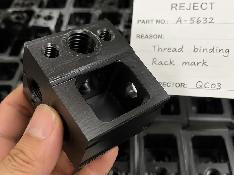
Early in our manufacturing history at Xiamen Dazao Machinery, our production facility contracted a production run of 500 units of Al6061-T6 avionics enclosure housings. The customer engineering print designated hard anodizing aluminum per MIL-A-8625 Type III Class 2 (Black) with a target coating thickness of 50 µm (0.002 in). The print omitted two essential details: pre-plating pitch diameter allowances for internal threads and designated racking contact faces.
The chemical process created two major defects:
1. Internal Thread Seizure: The 50 µm hardcoat expanded outward by 25 µm per side. On internal M6x1-6H threaded mounting holes, this outward growth caused a pitch diameter reduction of 0.100 mm (0.0039 in). Standard Class 3A assembly bolts bound completely at 1.5 turns during final assembly.
2. Vacuum Seal Leakage: The electro-plating line clamped titanium spring contacts directly onto an AS568-012 O-ring sealing face. The resulting 2.5 mm bare racking spot interrupted the continuous surface contact, causing helium leak rates exceeding 1×10⁻⁵ mbar⋅L/s under hydrostatic testing.
The scrap cost totaled $14,500 in raw materials, 5-axis CNC machining hours, and anodizing vendor processing fees. The project suffered a four-week schedule delay while replacement billets were sourced, machined with custom tap sizes, and processed using modified racking fixtures.
The Strategic Role of Surface Finishing Beyond Aesthetics
Surface treatment for aluminum transforms the chemical, mechanical, and electrical properties of the raw substrate:
· Corrosion Passivation: Native air-formed aluminum oxide (Al2O3) film measures only 2 to 5 nm in thickness, offering minimal protection against halides and moisture. Engineered anodic films increase this barrier layer to 5 to 50 µm, enabling resistance up to 1,000+ salt spray hours per ASTM B117.
· Wear & Tribological Improvement: Untreated aluminum exhibits high friction coefficients (μ≈0.60 to 0.70 against steel) and severe galling tendencies under sliding contact. Type III hardcoat increases surface microhardness from 95 HV (Al6061-T6 base) to 400 to 600 HV (60 to 70 HRC), dropping wear rates under ASTM D4060 Taber abrasion tests below 15 mg per 1,000 cycles.
· Dielectric Breakdown Strength: Anodized layers act as electrical insulators. A 25 µm Type II film provides dielectric breakdown voltage limits between 500V and 800V DC, whereas a 50 µm Type III hardcoat exceeds 1,500V DC breakdown capacity.
CNC machining merely establishes the geometric substrate. For an analysis of milling feeds, speeds, and alloy selections prior to surface conversion, consult our aluminum CNC machining guide. The post-machining aluminum finishing process determines long-term product viability in field deployments.
Deep Technical Breakdown of Core Finishing Processes for CNC Aluminum Parts
Selecting from available aluminum finishing options requires matching exact chemical, electro-bath, and mechanical media parameters against part performance demands fabricated via our custom 5-axis CNC machining services.

Type II Sulfuric Acid Anodizing (MIL-A-8625 Type II Class 1 & Class 2)
Type II anodizing is an electrochemical process conducted in an aqueous sulfuric acid electrolyte. The aluminum component serves as the anode, while lead or stainless steel cathodes complete the circuit.
Process Bath Parameters
· Electrolyte Concentration: Sulfuric acid (H2SO4) at 160 to 200 g/L (10 to 12% v/v).
· Dissolved Aluminum Content: Maintained strictly between 5 and 15 g/L to stabilize cell voltage.
· Operating Bath Temperature: 18∘C to 21∘C(64∘F to 70∘F). Chilling systems control exothermic heat generation at the part interface.
· Current Density: 1.2 to 1.5 A/dm2(11 to 14 A/ft2), driven by operating potential between 12 and 18 Volts DC.
· Film Growth Rate: Approximately 0.3 to 0.5 µm per minute. Total processing duration ranges from 20 to 50 minutes for standard 10 to 25 µm target thicknesses.
Microstructure and Pore Geometry
The anodic structure forms hexagonal oxide cells perpendicular to the substrate metal. Each hexagonal cell (50 to 80 nm wide) contains a central cylindrical micropore (12 to 15 nm diameter) extending down toward a thin barrier layer (10 to 30 nm thick) resting directly on the metallic aluminum. Cell density reaches approximately 1010 cells/cm2.
Dyeing Mechanics and UV Fastness of Black Anodized Aluminum Parts
Class 2 dyed anodizing draws dye molecules into open hexagonal pores via capillary action before sealing.
· Organic Azo Dyes: Offer broad color palettes but suffer from photon-induced chemical bond cleavage under solar radiation. UV exposure degrades organic black dyes, shifting surface appearance toward bronze or purple within 6 to 12 months of outdoor deployment.
· Inorganic Metal Salt Dyes: For high lightfastness (Rating 8 on the ISO 105-B02 Blue Wool Scale), black anodized aluminum parts are treated in inorganic bath sequences (e.g., cobalt acetate followed by ammonium sulfide, or ferric ammonium oxalate). Inorganic metallic compounds precipitate inside the pores, establishing UV stability under continuous solar exposure.
Type III Hardcoat Anodizing (MIL-A-8625 Type III Class 1 & Class 2)
Type III hard anodizing produces dense, thick ceramic alumina coatings optimized for high wear, abrasion, and dielectric performance.
Process Bath Parameters
· Electrolyte Composition: Sulfuric acid (H2SO4) at 180 to 220 g/L, augmented with 10 to 20 g/L oxalic acid (H2C2O4). Oxalic acid moderates chemical dissolution of the oxide film at higher current densities.
· Refrigerated Operating Temperature: −2∘C to +4∘C(28∘F to 39∘F). Low temperatures suppress acid dissolution, forcing dense oxide compaction.
· Current Density & Voltage Ramp: Operating current density ranges from 2.4 to 3.6 A/dm2(22 to 34 A/ft2). Rectifiers must dynamically ramp voltage from 24V up to 75V DC as film thickness and electrical resistance increase.
· Film Growth Rate: 0.7 to 1.2 µm per minute. Processing time ranges from 45 to 90 minutes to achieve 25 to 50 µm (0.001 to 0.002 in) specifications.
Microhardness and Tribological Properties
Microhardness measurements taken perpendicular to the cross-section per ASTM E384 yield values between 400 and 550 HV0.05 (equivalent to 60 to 70 HRC). Taber abrasion testing per ASTM D4060 (CS-17 wheels, 1,000g total load) shows weight loss below 15 mg per 1,000 cycles, outperforming hardened tool steels and hard chrome plating.
Hydration Sealing vs Wear Trade-Offs
Anodizing pores are closed post-treatment by immersion in boiling deionized water (>95∘C) or hot nickel acetate solution (85∘C to 90∘C). Water reacts with amorphous Al2O3 to form crystalline boehmite (AlO(OH)), which expands to plug pore openings.
Hydrothermal sealing decreases surface microhardness by 10 to 15% due to boehmite lattice softening. For extreme wear applications, drawings should state: MIL-A-8625 Type III Class 1 UNSEALED except where corrosion testing per ASTM B117 is required.
Mechanical Surface Treatments: Bead Blasting, Grit Blasting, and Polishing
Mechanical finishing alters surface topography by impacting or abrading the aluminum substrate with driven media.
Glass Bead Blasting Physics
Spherical soda-lime glass beads (Mohs hardness 6.0) deform surface micro-peaks plastically without cutting metal off the substrate.
· Media Sizing Specifications: Glass bead size #8 (0.150 to 0.250 mm diameter) creates medium matte textures; size #10 (0.106 to 0.180 mm) yields fine satin finishes; size #12 (0.075 to 0.150 mm) produces ultra-fine matte finishes.
· Operating Blast Pressure: Compressed air at 0.35 to 0.45 MPa (50 to 65 PSI), directed at a 60° to 90° angle from a distance of 100 to 150 mm.
· Roughness Reduction: Converts directionally milled surfaces from Ra 3.2 µm down to isotropic finishes between Ra 1.6 µm and Ra 0.8 µm.
Angular Aluminum Oxide Grit Blasting
Unlike spherical glass beads, fused brown or white aluminum oxide grit (Mohs hardness 9.0) features sharp, angular cutting edges.
· Grit Sizing: 120-mesh (100 to 150 µm) or 220-mesh (53 to 75 µm).
· Surface Anchor Profile: Cuts deep, sharp micro-cavities into the substrate, increasing total surface area by 200 to 300%. This anchor pattern improves adhesion for subsequent thermal spray, powder coating, or structural adhesive bonding.
· Surface Stress Transformation: Grit blasting induces compressive residual stress (σc≈−150 to −250 MPa) in the top 20 to 50 µm of the substrate, increasing fatigue life under cyclic loading per ASTM E466.
Mechanical Buffing and Electropolishing
· Mechanical Buffing: Sequential mechanical polishing using stitched cotton wheels loaded with coarse-to-fine aluminum oxide polishing compounds reduces roughness from Ra 1.6 µm down to Ra 0.2 µm.
· Electropolishing: An electrochemical smoothing process using phosphoric and sulfuric acid mixtures (H3PO4/H2SO4) operated at 60∘C to 80∘C with current densities of 15 to 25 A/dm2. Electropolishing selectively dissolves micro-peaks faster than micro-valleys, producing mirror reflectivity and roughness values below Ra 0.1 µm.
Chemical Conversion Coatings (MIL-DTL-5541 Type I & Type II)
Chemical conversion films (Chromate / Chem Film / Alodine) form thin, non-electrolytic passivating complex films on aluminum surfaces.
Type I Hexavalent Chromium Chemistry
Type I coatings use hexavalent chromium (Cr6+) compounds (e.g., chromic acid, sodium dichromate). The process yields a distinct golden-yellow to iridescent brown gelatinous film consisting of hydrated chromium oxide and aluminum oxide (Cr2O3⋅xH2O/Al2O3).
· Self-Healing Property: Unreacted Cr6+ ions trapped inside the gel matrix migrate to fresh scratches, re-passivating bare aluminum exposed by operational wear.
· Regulatory Restriction: Restricted under RoHS and REACH directives due to hexavalent chromium toxicity.
Type II Trivalent Chromium Process (TCP)
Type II coatings utilize trivalent chromium (Cr3+) salts and fluorozirconic acid (H2ZrF6). TCP forms a clear to light-blue tinted film containing zirconium oxide (ZrO2) and trivalent chromium complex structures.
· RoHS Compliance: Fully compliant with global environmental directives.
· Coating Thickness: Extremely thin (0.2 to 0.8 µm), keeping dimensions unchanged.
· Electrical Contact Resistance: Maintains high surface conductivity per MIL-DTL-81706 (<5000 μΩ/in2 under 200 PSI electrode contact pressure). It is widely specified for EMI/RFI shielded electronic enclosures.
· Corrosion Resistance: Exceeds 168 hours of salt spray exposure per ASTM B117 without corrosion pitting.
Powder Coating & Industrial Paint Systems
Powder coating applies electrostatically charged thermosetting polymer powders onto aluminum components, which are subsequently cured in industrial ovens.
Process Sequence
1. Pre-treatment: Multi-stage alkaline degreasing, acid etch, and application of a Trivalent Chromate conversion layer to ensure polymer adhesion.
2. Electrostatic Deposition: Corona spray guns charge powder particles negatively at 60 to 90 kV. The grounded aluminum part draws the charged powder uniformly across exterior surfaces.
3. Thermal Curing Cycle: Parts pass through a convection oven held at 180∘C to 200∘C(356∘F to 392∘F for 15 to 20 minutes. The polymer melts, flows, cross-links, and hardens into a continuous protective shell.
Polymer Chemistry Options
· Polyester TGIC / TGIC-Free: Excellent UV durability and chalk resistance, making it the industry standard for outdoor enclosures.
· Epoxy Systems: Exceptional chemical and impact resistance, but prone to chalking and UV degradation under direct sunlight.
· Polyurethane: Provides high chemical resistance, smooth aesthetic flow, and scratch resistance.
Coating Build Dynamics and DFM Rules
Powder coatings deposit a heavy layer measuring 60 to 120 µm (0.0024 to 0.0047 in). Engineers must specify high-temperature silicone plug or cap masking on all internal threads, bearing bores, and precision flat mating faces.
Electroless Nickel Plating (MIL-C-26074 / ASTM B733)
Electroless Nickel Plating (ENP) deposits an auto-catalytic nickel-phosphorus (Ni-P) alloy film without external electrical current.
Bath Chemistry and Deposition Mechanics
The aqueous bath contains nickel sulfate (NiSO4) as the nickel source and sodium hypophosphite (NaH2PO2)as the reducing agent, operated at 85∘C to 90∘C with a controlled pH between 4.5 and 4.8.
Ni2++2H2PO2−+2H2O  Ni0+2H2PO3−+H2↑+2H+
Phosphorus Content Classifications
· Low Phosphorus (2 to 4% P): High hardness as deposited (600 to 700 HV), optimized for wear resistance in alkaline environments.
· Medium Phosphorus (6 to 9% P): Standard commercial grade balancing deposition speed, ductility, and moderate corrosion protection.
· High Phosphorus (10 to 12% P): Completely amorphous non-magnetic structure. Demonstrates high acid corrosion resistance, withstanding 1,000+ salt spray hours per ASTM B117.
Uniformity and Post-Bake Hardening
Unlike electroplating processes that build up heavily on exterior sharp corners, electroless nickel deposits uniformly (±1 μm) across all wet surfaces, including deep internal bores, cross-holes, and blind cavities.
Post-plating heat treatment at 350∘C to 400∘C for 1 hour induces nickel phosphide (Ni3P) precipitation hardening, raising deposit microhardness to 900 to 1,000 HV (equivalent to 68 HRC).
Comprehensive Finishing Process Parameter Matrices
Table 1: Electrochemical Bath Chemistry and Operating Parameters
|
Parameter |
Type II Anodizing |
Type III Hardcoat |
Trivalent Chem Film (TCP) |
Electroless Nickel (ENP) |
|
Primary Chemicals |
H2SO4(160–200 g/L) |
H2SO4(180–220 g/L) + Oxalic |
Cr3+ salts + H2ZrF6 |
NiSO4 + NaH2PO2 |
|
Operating Temperature |
18°C to 21°C |
-2°C to +4°C |
20°C to 30°C |
85°C to 90°C |
|
Current Density |
1.2 to 1.5 A/dm2 |
2.4 to 3.6 A/dm2 |
Non-electrolytic |
Non-electrolytic |
|
Voltage Range |
12V to 18V DC |
24V to 75V DC Ramp |
N/A |
N/A |
|
Deposition Rate |
0.3 to 0.5 µm/min |
0.7 to 1.2 µm/min |
Reaction time 1–3 min |
12 to 20 µm/hour |
|
Thickness Range |
5 to 25 µm |
25 to 50 µm |
0.2 to 0.8 µm |
10 to 25 µm |
Table 2: Mechanical Finishing Media, Operating Parameters, and Roughness Output
|
Media Type |
Media Geometry |
Sizing Range |
Air Pressure |
Initial Ra (µm) |
Resulting Ra (µm) |
|
Glass Beads (#8) |
Spherical |
0.150–0.250 mm |
0.35–0.45 MPa |
3.2 |
1.2 to 1.6 |
|
Glass Beads (#10) |
Spherical |
0.106–0.180 mm |
0.35–0.45 MPa |
3.2 |
0.8 to 1.2 |
|
Glass Beads (#12) |
Spherical |
0.075–0.150 mm |
0.30–0.40 MPa |
1.6 |
0.4 to 0.8 |
|
Al2O3 Grit (120 Mesh) |
Angular |
0.100–0.150 mm |
0.40–0.55 MPa |
3.2 |
1.8 to 2.4 |
|
Mechanical Buffing |
Wheel + Compound |
N/A |
Manual / Robot |
1.6 |
0.1 to 0.3 |
Table 3: Performance, Hardness, and Industry Standard Specification Matrix
|
Finish Option |
Specification |
Hardness (HV/HRC) |
Salt Spray Rating |
Electrical Properties |
Thickness Tolerance |
|
Type II Anodizing |
MIL-A-8625 Type II |
200–300 HV |
336 Hours |
Insulator (>500V) |
±3 μm |
|
Type III Hardcoat |
MIL-A-8625 Type III |
400–600 HV (60 HRC) |
1,000+ Hours |
High Insulator (>1500V) |
±5 μm |
|
Chem Film (TCP) |
MIL-DTL-5541 Type II |
Substrate Baseline |
168 Hours |
Conductive (<0.01 Ω) |
±0.2 μm |
|
Powder Coating |
ASTM D3363 |
2H–4H Pencil |
500–1,000 Hours |
Insulator |
±15 μm |
|
Electroless Nickel |
MIL-C-26074 |
500–1,000 HV(68HRC) |
500+ Hours |
Conductive |
±2 μm |
Hidden Pitfalls: Three Critical Engineering Traps in Aluminum Finishing
Standard finishing guides review process definitions but ignore practical shop-floor failure modes. Below are three critical engineering failure mechanisms identified during production runs at Dazao Machinery.
Bi-Directional Film Growth Mechanics and Internal Thread Tolerance Calculations
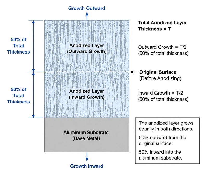
Anodizing is an electrolytic conversion reaction where oxide growth occurs 50% inward into the substrate and 50% outward from the original surface.
Mathematical Growth Derivation
For a specified total anodic film thickness Ttotal:
Outward Dimension Growth per Surface (Toutward)=0.5×Ttotal
Inward Substrate Penetration (Tinward)=0.5×Ttotal
External Cylindrical Features (Shafts/Pins): The final outside diameter Dfinal expands relative to the pre-plated diameter Dinitial:
Dfinal=Dinitial+(2×Toutward)=Dinitial+Ttotal
Internal Cylindrical Features (Bores/Holes): The final inside diameter dfinal reduces relative to the pre-plated diameter dinitial:
dfinal=dinitial−(2×Toutward)=dinitial−Ttotal
Compound Growth Dynamics on 60∘Internal Threads
For internal threads with a standard 60∘thread flank angle (ASME B1.1 / ISO 68-1), outward growth on the thread flanks reduces pitch diameter at a geometric ratio of 4:1 relative to outward thickness per side:

If an engineer specifies 50 µm (0.002 in) Type III hardcoat on an internal M6x1-6H thread without pre-plate allowance:
· Outward growth per flank: Toutward=25 μm(0.025 mm).
· Pitch diameter reduction: ΔDpitch=4×0.025 mm=0.100 mm(0.0039 in).
This 0.100 mm pitch diameter shrink exceeds standard 6H pitch tolerances (≈0.026 mm limit), causing assembly fasteners to bind instantly.
Pre-Plate Thread Allowance Calculation Table
|
Nominal Metric Thread |
Standard Pitch |
Standard Pitch Tolerance (6H) |
Pre-Plate Pitch Oversize: Type II (15 µm Coating) |
Pre-Plate Pitch Oversize: Type III (50 µm Hardcoat) |
Required Tap Modification |
|
M3 x 0.5 |
0.50 mm |
+0.085 / 0 mm |
+0.030 mm |
+0.100 mm |
Custom Oversize Tap |
|
M4 x 0.7 |
0.70 mm |
+0.095 / 0 mm |
+0.030 mm |
+0.100 mm |
Custom Oversize Tap |
|
M5 x 0.8 |
0.80 mm |
+0.106 / 0 mm |
+0.030 mm |
+0.100 mm |
Special 6G Pitch Tap |
|
M6 x 1.0 |
1.00 mm |
+0.112 / 0 mm |
+0.030 mm |
+0.100 mm |
Special 6G Pitch Tap |
|
M8 x 1.25 |
1.25 mm |
+0.125 / 0 mm |
+0.030 mm |
+0.100 mm |
Special 6G Pitch Tap |
|
M10 x 1.5 |
1.50 mm |
+0.140 / 0 mm |
+0.030 mm |
+0.100 mm |
Special 6G Pitch Tap |
Metallurgical Grain Structure and Heat-Treatment Effects on Color Delta E
Color mismatch between components in an assembly (Delta E > 2.5) remains a common customer rejection mode. This variation is driven by alloy chemical segregation and heat-treatment history.
Metallurgical Intermetallic Phase Segregation
For detailed physical and chemical property comparisons when machining 6061-T6 and 7075-T6 aluminum alloys, intermetallic phase segregation dictates surface finish results.:
· Al6061-T6: Contains Mg2SiMg2Si precipitates. During sulfuric acid anodizing, Mg2Si dissolves uniformly, leaving a clear alumina matrix (Al2O3) with high optical transparency and a refractive index n≈1.76. This allows organic and inorganic dyes to reflect vibrant, uniform colors.
· Al7075-T6: Contains zinc (5.6–6.1%), magnesium (2.1–2.5%), and copper (1.2–1.6%). Copper forms intermetallic Al2CuMg (θ-phase) particles along grain boundaries. These phase boundaries dissolve at different oxidation rates, creating a dark, cloudy oxide matrix that shifts dye absorption toward brownish, desaturated tones.
CIELAB Spectrophotometric Measurement
Color difference is quantified using the CIELAB L∗a∗b∗color space per ASTM D2244:

Where L∗represents lightness, a∗measures red/green value, and b∗measures yellow/blue value. A  >1.0 is visible to the trained human eye;
  >2.5 causes visible assembly rejections.
Dazao Process Control for Multi-Part Color Consistency
At Dazao Machinery, our ISO9001 and IATF16949 certified quality control system enforces strict raw material traceability to eliminate lot-to-lot color shifts.
1. Material Traceability: Lock raw material procurement to a single mill heat lot for all visual mating components in a product run.
2. Temper Standardisation: Never mix Al6061-T5 extrusions with Al6061-T6 machined plate within the same color batch.
3. Current Density Modulation: Reduce current density to 1.2 A/dm2 when processing Al7075 components to mitigate copper phase burning in the acid bath.
Micro-Porosity Oil Traps and Trapped Acid Bleedout in Threaded Blind Holes
Capillary Action in Matte Finish Surfaces
Bead blasting transforms smooth surfaces into a dense topography of micro-cavities. According to Young-Laplace capillary pressure principles:

Where γ is liquid surface tension, θ is contact angle, and r is pore radius. As r drops below 5 µm on unsealed matte surfaces, capillary pressure increases drastically. Human skin oils (sebum) are drawn into open micro-cavities, producing permanent dark finger marks that resist solvent wiping.
Engineering Fix: Mandate hot nickel acetate hydrothermal sealing (85∘C to 90∘C for 20 minutes) post-dyeing to hydrate and plug micro-pores before assembly handling.
Acid Bleedout Mechanisms in Deep Blind Tapped Holes
Deep blind threaded cavities (e.g., M3 threads deeper than 8 mm) act as air traps when submerged in chemical processing lines. Air pockets trap sulfuric acid (H2SO4) inside the bottom threads. Standard immersion water rinses fail to flush trapped acid due to surface tension barriers.

Over 14 to 21 days in transit, trapped sulfuric acid reacts with the aluminum cavity walls, bleeding outward to form white aluminum sulfate hydrates:
2Al+3H2SO4+18H2O→Al2(SO4)3⋅18H2O+3H2↑
This white powder corrodes adjacent surfaces, degrades decorative coatings, and causes fastener seizure.
Dazao Blind Hole Prevention Protocol
· DFM Modification: Add a small relief cross-hole (∅1.0 to 1.5 mm) at the base of blind holes to allow fluid flow.
· Ultrasonic Neutralization: Run parts through an ultrasonic bath containing 5% w/v sodium bicarbonate (NaHCO3) solution at 50°C and 40 kHz frequency to neutralize trapped acidic residues.
Field Solutions: Managing Rack Marks, Transport Scratches, and Thermal Stress
Managing Rack Contact Marks on Visual Surfaces
Anodizing requires titanium or aluminum racking fixtures to deliver high DC currents (12 to 24V, up to hundreds of Amperes). Current density at contact points (J≥15 A/cm2) prevents oxide film formation where the rack grips the component, leaving a bare aluminum mark (1.0 to 3.0 mm wide).
Engineering drawings must explicitly specify allowable racking zones using a flag note: Rack contacts allowed only inside feature X; no rack marks permitted on visual faces A or B.
Transport Abrasion Protocols on Matte Sandblasted Components
Matte bead-blasted surfaces consist of delicate micro-peaks. During ocean transit, vibration (10 to 500 Hz) causes adjacent parts in standard poly bags to rub together, shearing micro-peaks and creating shiny polished contact marks along sharp edges.
Dazao Protective Packaging Standard
· Individual compartment thermoformed Electrostatic Discharge (ESD) plastic trays.
· Interleaving with high-density non-abrasive foam (EPE foam≥20 mm).
· Vacuum sealing with Volatile Corrosion Inhibitor (VCI) film to prevent humidity-induced oxidation during ocean shipping.
Thermal Crazing in High-Temperature Operating Environments
Aluminum has a high Coefficient of Thermal Expansion (αAl≈23.1×10⁻⁶/K), whereas the ceramic anodized layer (Al2O3) expands at a much lower rate (αoxide≈8.1×10⁻⁶/K).
When an anodized part is exposed to temperatures above 80°C (176°F), differential expansion creates high tensile stress within the anodic coating:
εthermal=(αAl−αoxide)×ΔT
When thermal strain exceeds oxide fracture strength, microscopic parallel fractures form across the surface. This phenomenon, known as thermal crazing, compromises dielectric breakdown strength and corrosion resistance.
High-Temperature Engineering Alternatives
For components operating continuously above 100°C (212°F):
· Limit anodic film thickness to < 15 µm (Type II).
· Replace hardcoat anodizing with Trivalent Chem Film (MIL-DTL-5541 Type II) or Electroless Nickel Plating (MIL-C-26074).
Cost Optimization: Balancing Surface Roughness (Ra) and Machining Cycles
Achieving low surface roughness values increases machining cycle time and tooling costs exponentially. To minimize unit production costs, engineering teams should evaluate cutter stepover parameters during the CNC aluminum machining process before adding secondary blasting or anodizing operations.

Roughness vs Machining Cost Breakdown
|
Surface Finish Level |
Ra Value (µm) |
Ra Value (µin) |
Primary Manufacturing Method |
Relative Cost Multiplier |
|
Rough Machined |
6.3 |
250 |
Heavy rough milling |
1.0×(Baseline) |
|
Standard Machined |
3.2 |
125 |
Standard 3-axis CNC milling |
1.2× |
|
Fine Machined |
1.6 |
63 |
High-speed finishing pass / small stepover |
1.8× |
|
Bead Blasted |
0.8 |
32 |
Standard CNC (Ra 3.2) + Glass bead blast |
1.4×(Cost-Effective Option) |
|
Precision Polished |
0.2 |
8 |
Multi-stage hand/buffing or electropolish |
3.5× to 5.0× |
Cost Reduction Recommendation
To conceal cutter stepover lines without incurring expensive fine-milling cycle times:
1. Machine parts to standard Ra 3.2 µm.
2. Specify glass bead blast (#10 media) followed by Type II anodizing.
3. This process combination produces a uniform satin finish while reducing overall machining costs.
Standard Surface Finish Drawing Callout Template
Copy and paste this notes block directly into your CAD engineering prints:
Finishing Notes:
1. MATERIAL: Aluminum 6061-T6 per AMS-QQ-A-250/11.
2. SURFACE TREATMENT: Hardcoat Anodize per MIL-A-8625, Type III, Class 2 (Black).
3. COATING THICKNESS: 35 µm ± 5 µm (0.0014 in ± 0.0002 in).
4. DIMENSIONAL APPLICABILITY: All dimensions and tolerances apply AFTER surface finishing.
5. PRE-PLATE TOLERANCING: Internal threads M6x1-6H must be tapped +0.06mm oversize prior to anodizing.
6. RACKING RESTRICTIONS: Rack marks permitted ONLY on internal surface [Feature C]. NO rack marks on sealing face [Feature A].
7. ROUGHNESS: Surface roughness prior to anodizing shall be Ra 1.6 µm max per ISO 4287.
Actionable Takeaways for Procurement and Engineering Teams
Specifying a cnc aluminum surface finish requires coordinating material selection, physical growth dynamics, and mechanical tolerances. Treating finishing specifications as core engineering parameters prevents component failures, dimensional rejections, and unnecessary project costs.
Xiamen Dazao Machinery brings 24 years of custom manufacturing experience to every project. Our engineering team reviews all CAD models and drawing notes through a structured DFM process to resolve tolerance issues, racking constraints, and finishing challenges before production begins.

FAQs
01.Why does chemical stripping damage tolerances when re-anodizing aluminum parts?
02.How do you remove finger oil stains from sandblasted matte anodized aluminum?
03.Why do black anodized aluminum parts fade or turn purple outdoors?
04.How do you prevent white acid bleedout corrosion from blind tapped holes?
05.Can 6061 and 7075 aluminum components achieve an exact color match?
06.How do you prevent rack contact marks from ruining critical sealing faces?