


Tooling misapplication accounts for more machining failures, dimensional non-conformance, and unplanned downtime than spindle kinematic errors. Achieving minimum part cost and strict tolerances requires matching substrate physics, flute count, and core geometry directly to the workpiece material and machine envelope. Replacing zero-radius square end mills with 0.5 mm to 1.0 mm corner radius end mills increases tool life by up to 50% while allowing a 20% higher feed per tooth. For Al6061-T6 and Al7075 aerospace components, polished 3-flute carbide mills with ZrN or DLC coatings prevent chip welding, while standard TiAlN coatings must be avoided due to chemical affinity.
Tool Failure Economics: The True Engineering Cost of End Mill Selection in CNC Milling
An audit of scrap bins across production facilities running 3-axis and 5-axis vertical machining centers typically points to a consistent root cause: premature tool failure and cutter deflection, rather than programmer error or machine axis positioning error. When precision components have critical features held to strict CNC machining tolerance and GD&T limits, tool instability directly causes dimensional rejection.
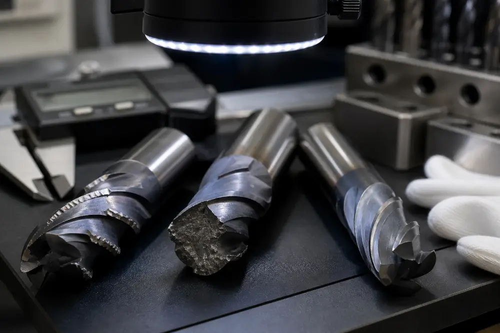
When an end mill experiences accelerated flank wear, built-up edge (BUE), or sudden micro-chipping, the resulting cutting force spike induces chatter, destroys surface finishes beyond Ra 0.8 µm specifications, and causes dimensional taper on deep vertical walls. In high-mix, close-tolerance contract manufacturing, tooling costs rarely represent more than 3% to 5% of the total manufacturing budget. Yet, poor tooling decisions directly influence the overall aluminum CNC machining cost breakdown across production batches, dictating the remaining 95% of operational expenses through cycle-time inflation, manual bench rework, and scrapped semi-finished stock.
Procurement departments frequently target a 15% reduction in tool acquisition cost by sourcing generic, economy-grade cutters. In production environments where spindle operation runs between $75 and $160 per hour, a cheaper tool that forces a machinist to reduce radial depth of cut or chip load by 25% to prevent chatter drives the piece-part cost up significantly.

At Xiamen Dazao Machinery, machining millions of components through our multi-axis precision CNC machining services under ISO9001:2015 and IATF16949:2016 controls has proven that precision manufacturing demands a structured end mill selection guide. Tool selection must be treated as a deterministic mechanical calculation involving material shear stress, chip thinning physics, dynamic tool overhang, and thermal dissipation, rather than a matter of operator preference.
Tool Substrate Selection: Carbide vs HSS End Mills Performance Thresholds
The choice between tungsten carbide and high-speed steel (HSS) sets the absolute ceiling for surface footage, tool deflection resistance, and thermal durability. Choosing the incorrect substrate guarantees premature failure before the cutting edge ever engages at its programmed feed rate. Evaluating carbide vs HSS end mills requires examining their material behavior under dynamic heat and mechanical load.
Physical and Mechanical Boundaries
Solid carbide end mills are sintered composite materials consisting of sub-micron tungsten carbide grains embedded in a metallic cobalt binder matrix, typically containing 6% to 12% cobalt by weight. High-speed steel, specifically premium grades like M42 containing 8% cobalt, relies on iron-carbon-tungsten-molybdenum alloying.
The primary physical differentiator is the Modulus of Elasticity. Solid carbide possesses an elastic modulus ranging from 550 to 650 GPa, which is nearly three times stiffer than the 200 to 210 GPa of HSS. Deflection is inversely proportional to the tool elastic modulus:
· Solid carbide exhibits approximately one-third the lateral bending deflection of an identical HSS cutter under identical radial cutting forces.
· Solid carbide retains a hardness of 89 to 93 HRA up to working temperatures of 800°C to 900°C.
· M42 cobalt HSS loses hardness rapidly once cut-zone temperatures exceed 550°C due to temper softening, leading to immediate edge rounding.
|
Mechanical Property |
Sub-Micron Solid Carbide (10% Co) |
M2 Standard High-Speed Steel |
M42 8% Cobalt High-Speed Steel |
|
Hardness |
91.5 - 92.5 HRA (approx. 76 HRC) |
63 - 65 HRC |
66 - 68 HRC |
|
Modulus of Elasticity (GPa) |
580 - 620 |
205 |
215 |
|
Thermal Conductivity (W/m·K) |
80 - 100 |
19 - 24 |
21 - 25 |
|
Max Working Temp Before Softening |
850°C - 900°C |
500°C |
550°C |
|
Deflection Resistance Ratio |
2.85x (Benchmark) |
1.0x (Base) |
1.05x |
|
Cutting Speed Capacity (SFM in Steel) |
400 - 1,200 SFM |
70 - 120 SFM |
100 - 180 SFM |
The Prototype Myth vs. Production Reality
A persistent misconception among junior manufacturing engineers suggests that HSS is preferable for short-run prototypes or soft materials due to lower upfront unit pricing.
On modern CNC milling centers with 10,000 to 24,000 RPM spindles, using HSS creates significant bottlenecks. In Al6061-T6, carbide routinely operates at surface cutting speeds exceeding 1,500 to 3,000 SFM (450 to 900 m/min). Running an HSS tool at these speeds causes immediate thermal failure at the cutting edge within seconds of engagement. Restricting spindle speed to preserve HSS extends cycle times by 300% to 500%.
Furthermore, HSS exhibits lower abrasion resistance when processing abrasive alloys such as hypereutectic cast aluminum or 300-series stainless steels. Dazao machine shop floor records show that an HSS cutter processing 304 stainless steel loses sharp edge radius within 150 linear inches of cut, driving cutting forces up and generating surface burrs that require secondary manual deburring. Solid micrograin carbide maintains edge sharpness over 1,800 to 2,500 linear inches under identical cutting parameters.
Operational Application Boundaries
The application window for HSS in modern machining has narrowed to specific scenarios:
1. Severe Interrupted Cuts on Low-Rigidity Machinery: Manual knee mills, aging machinery with excessive backlash, or setups with unstable mechanical fixturing where the brittle nature of solid carbide risks catastrophic fracture under high-amplitude impact shock.
2. Extreme Deep-Reach Form Tools with Vibration: Custom specialized form profiles where the tool body must flex slightly to absorb chatter rather than shattering, provided cutting speeds are adjusted downward to avoid exceeding thermal thresholds.
For all automated production setups deployed in automated production CNC milling cells, rigid setups, and materials above 28 HRC, solid carbide remains the technical baseline.
Cutter Geometries & Operations: Types of End Mills and Their Uses in Precision Machining
Selecting the correct cutter architecture requires matching tool geometry to component features, wall perpendicularity requirements, and targeted material removal rates. Understanding the structural types of end mills and their uses allows process planners to optimize tool life and surface finish systematically.
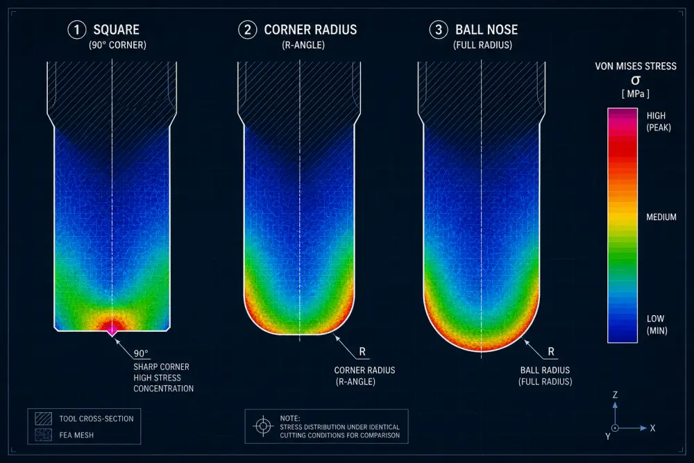
Square End Mills: Shoulder Squaring and Micro-Chipping Risks
Square end mills feature flat bottoms with sharp 90-degree outer corners.
· Primary Operations: Squaring internal steps, cutting true 90-degree floor-to-wall interfaces, slotting, and flat-bottom blind holes.
· Failure Modes: The sharp corner tip represents the weakest zone on the entire cutting tool. Because heat and mechanical stresses concentrate at this single intersection point of the peripheral and end-cutting edges, micro-chipping occurs almost immediately when engaging hard materials or handling interrupted profiling. Once the corner chips, cutting forces spike, causing the remaining peripheral flute to peel away rapidly.
Ball Nose vs Square End Mill: 3D Contouring Mechanics and the Zero-Velocity Center Point
In 3D profiling, deep-pocket contouring, and mold-cavity manufacturing, evaluating ball nose vs square end mill performance highlights a major physical limitation: the center dead zone.
· Ball Nose Characteristics: The cutting radius equals half the tool diameter, providing continuous transition paths across complex contoured surfaces.
· The Zero-Velocity Centerline Limitation: The effective cutting velocity of a rotating tool depends directly on the contact diameter. At the absolute tip centerline of a ball nose end mill, the surface cutting speed drops to zero meters per minute, regardless of spindle RPM.
· The Result: When plunging or clearing flat shallow floors with a ball nose cutter, the center does not shear material cleanly; it extrudes, smothers, and tears the metal. This rubbing generates rapid localized frictional heat, resulting in center galling, built-up edge, and rough surface profiles (Ra > 3.2 µm).
· Engineering Mitigation: In 5-axis machining operations, Dazao engineers program a lead angle of 10 to 15 degrees. Tilting the spindle shifts the point of contact away from the dead-center zero-velocity zone to an active peripheral zone with adequate cutting velocity.
The Corner Radius Alternative: Relieving Stress to Increase Tool Life and Feed Rates
One of the most effective methods to improve milling efficiency is replacing standard square end mills with corner radius end mills (bull nose cutters) for roughing and semi-finishing operations; designers can reference our analysis on machining corner radius cost factors to understand the financial impact on component drawing specifications.
A square end mill has a corner radius of zero, creating a sharp stress concentration point. Specifying a corner radius, such as 0.5 mm, 1.0 mm, or 1.5 mm, distributes cutting impacts across a rounded profile rather than concentrating them on a single point.
Field tests conducted across Dazao machining cells show clear operational benefits:
1. 40% to 55% Increase in Tool Life: Distributing mechanical stress prevents corner chipping, ensuring predictable, gradual flank wear progression.
2. 20% Higher Feed Per Tooth: The curved corner profile introduces a localized chip-thinning effect, allowing increased table feed rates without exceeding maximum permissible chip thickness limits.
3. Reduced Floor Gouging: When clearing expansive flat floors on dynamic vertical machining centers, a minute 0.5 mm radius eliminates the micro-steps and witness marks left behind by square corner tips during high-feed passes.
Unless an engineering drawing strictly specifies a sharp internal 90-degree corner without relief, standardizing roughing and clearing operations on corner radius end mills significantly lowers tooling expenses.
Roughing End Mills: Sinusoidal Flutes for High-Volume Material Removal
Roughing end mills feature flutes with undulating, sinusoidal chip-breaker ridges along their outer periphery.
These wavy ridges break long, continuous metal shavings into small, segmented chips. By keeping chip length short, the tool drastically reduces radial cutting forces and prevents chip recutting in deep cavities. Roughing end mills allow high axial depth of cut engagement, making them effective for high-tensile alloy steels, titanium alloys, and heavy casting stock where machine spindle torque is the limiting factor. The resulting trade-off is a textured wall finish (Ra 6.3 to 12.5 µm), requiring a secondary semi-finishing and finishing pass using a standard continuous-flute tool.
Chamfer and Tapered End Mills: Draft Angles and Automated Edge Breaking
· Chamfer Mills: Dedicated multi-flute conical tools designed for automated edge-break operations, weld preps, and internal countersinking. Using dedicated chamfer tools at elevated feeds eliminates the need for manual deburring, holding uniform edge breaks within tight ±0.002 in (±0.05 mm) drawing limits.
· Tapered End Mills: Cutters featuring angled side profiles (typically 0.5° to 15° per side) engineered specifically for milling mold-cavity draft angles, structural aerospace web pockets, and turbine blade root slots. Using a tapered end mill avoids the staircase micro-ridges caused by standard tooling stepover routines, producing smooth wall transitions within a single pass.
|
Tool Geometry Type |
Primary Applications |
Tool Deflection Rigidity |
Edge Failure Mode |
Preferred Workpiece Alloys |
|
Square End Mill |
True 90° shoulders, bottom step cleanup, slotting |
Baseline |
Corner chipping and micro-fracture |
Cast irons, structural carbon steels, plastics |
|
Corner Radius End Mill |
Pocket roughing, 2D profiling, heavy floor clearing |
High (+15% vs square) |
Predictable, uniform flank wear |
Titanium, stainless steels, Al6061-T6, tool steels |
|
Ball Nose End Mill |
3D complex contouring, mold cavity surfacing |
Moderate to High |
Center dead-zone smearing and abrasive wear |
Hardened tool steels (>50 HRC), nickel superalloys |
|
Roughing End Mill |
High-volume metal removal, deep pocket hogging |
Very High (Low radial load) |
Gradual tooth-crest degradation |
Inconel 718, 4140 pre-hardened steel, heavy raw forgings |
|
Tapered End Mill |
Die cast mold draft angles, aerospace rib profiling |
Maximum (Conical core) |
Lower-edge flute wear |
Forged aluminum, mold steels (P20, H13) |
Non-Ferrous Milling Strategy: Selecting the Best End Mill for Aluminum CNC
Machining wrought aluminum alloys such as Al6061-T6, Al7075-T651, and cast grades like A380 presents distinct tribological challenges compared to ferrous machining; as detailed in our manufacturing guide to aluminum CNC machining, non-ferrous alloys demand specialized clearance geometries. Aluminum features a low melting point, high thermal conductivity, and a strong chemical affinity for cutting tool substrates. Under cutting temperatures above 350°C, ductile aluminum chips rapidly weld to the cutting edge, forming a built-up edge. This edge build-up clogs flutes within revolutions and shears the tool. Selecting the best end mill for aluminum CNC requires deliberate flute design and chip evacuation management.

Flute Evacuation Dynamics: 2 Flute vs 3 Flute End Mill for Aluminum
The debate between a 2 flute vs 3 flute end mill for aluminum hinges on the trade-off between chip gullet volume and tool core rigidity when cutting end mills aluminum applications.
· 2-Flute End Mills: Feature massive, open chip valleys that maximize space for chip clearance. They excel in deep, non-peck slotting operations where axial depth equals tool diameter, as well as steep ramping and plunge milling. However, the smaller web diameter (typically 40% to 45% of outer diameter) makes the tool vulnerable to bending deflection, restricting allowable feed rates during peripheral profiling passes.
· 3-Flute End Mills: Provide the optimal structural balance for modern CNC milling. The tool core diameter increases to 55% to 60% of outer diameter, yielding more than double the structural stiffness of a 2-flute tool. This increased core rigidity eliminates wall chatter during high-speed finishing passes. Operating three cutting flutes enables a 50% increase in table feed at an identical chip load per tooth, in accordance with standard high-speed machining aluminum protocols, maximizing material removal rates without sacrificing chip evacuation.
Dazao standardizes on 3-flute polished carbide end mills for 85% of structural aerospace aluminum components, reserving 2-flute geometries strictly for full-width slotting deeper than 1.5 times the cutter diameter.
High Helix Hazards: Mitigating Axial Tool Pull-Out and Collet Slippage
Industry guides often suggest using steep helix angles (45° to 50°) for aluminum tools to produce high shear angles and lower cutting forces. While steep helix geometries shear aluminum cleanly and eject chips upward efficiently, they introduce a significant mechanical hazard: excessive axial pulling forces.
As the helix angle increases from 30° to 45°, the resultant vector of the cutting force shifts dramatically along the tool axis, pulling the tool downward away from the spindle. In heavy roughing cuts using standard ER32 or ER40 collet chucks, this axial lifting force frequently exceeds the frictional clamping force of the collet sleeve. The cutter creeps outward along its Z-axis, gouging floor dimensions and scrapping expensive billets.
To prevent tool pull-out during aggressive high-speed roughing of aluminum, Dazao implements strict shop-floor standards:
1. Hydraulic and Heat-Shrink Tool Holders: Tooling assemblies with high grip force and runout within 0.003 mm (0.0001 in) replace standard ER collet chucks for high-load operations.
2. Positive Mechanical Retention Systems: Mechanical lock shank configurations are deployed when operating large cutters (diameters 16 mm / 0.625 in and above) in high-feed roughing cells.
3. Optimized Helix Compromise: Utilizing a variable helix geometry (38° to 42°) disrupts chatter harmonics while maintaining manageable axial pull-out forces.
Thin-Film Coating Tribology: End Mill Coatings for Aluminum and Ferrous Alloys
Applying the wrong surface coating to a precision milling tool causes immediate degradation in surface finish and rapid tool fracture. Specifying proper end mill coatings for aluminum requires understanding the chemical compatibility between the workpiece material and thin-film layers.
The Solid-State Welding Hazard: Why TiAlN Coatings Fail in Aluminum
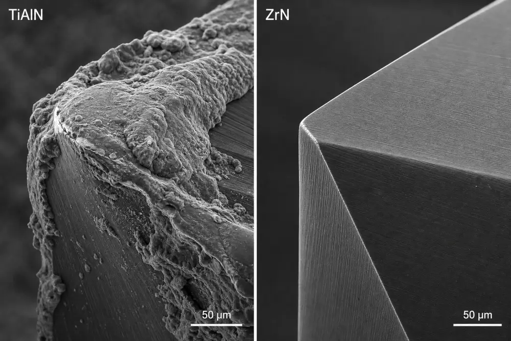
A frequent tooling mistake in job shops is selecting Titanium Aluminum Nitride (TiAlN) or Aluminum Titanium Nitride (AlTiN) coated cutters to machine Al6061 or Al7075 components.
TiAlN and AlTiN coatings depend on the oxidation of aluminum within the coating matrix to form a protective aluminum oxide ceramic barrier at elevated temperatures (above 700°C). When cutting aluminum, the chemical affinity between the aluminum in the workpiece and the aluminum in the coating triggers solid-state micro-welding at moderate contact temperatures. Chips adhere to the cutting edge, the flutes pack with material within seconds, and the tool snaps. TiAlN and AlTiN coatings must never be used on non-ferrous alloys.
Advanced Non-Ferrous Coatings: Uncoated Mirror Polish, ZrN, and DLC
For non-ferrous materials, cutting performance relies on non-reactive surfaces with ultra-low friction coefficients:
· Uncoated with Mirror-Polished Flutes: The baseline standard for aluminum. Flutes diamond-lapped to a mirror finish (Ra < 0.1 µm) lower friction, allowing smooth chip flow across the rake face without adhesion.
· Zirconium Nitride (ZrN): Provides extreme lubricity and resistance to aluminum adhesion. The pale-gold coating maintains edge sharpness while extending tool life by 2.5 to 3.5 times compared to bright carbide in abrasive cast aluminum.
· Diamond-Like Carbon (DLC): An amorphous carbon coating combining high micro-hardness (3,000 to 5,000 HV) with an ultra-low coefficient of friction (below 0.1). DLC prevents built-up edge formation, making it ideal for deep-pocket profiling in gummy aluminum and dry aerospace structural milling.
Ferrous and Superalloy Surface Treatments: TiAlN, AlCrN, and Nanocomposite TiSiN
For ferrous applications, oxidation resistance and thermal stability drive the selection criteria:
· TiAlN / AlTiN: Standard for pre-hardened steels, tool steels (30 to 45 HRC), and gray cast iron. Operates effectively in high-heat dry milling conditions up to 800°C.
· AlCrN (Aluminum Chromium Nitride): Outperforms TiAlN in stainless steels (304, 316L) and high-load milling. Resists thermal shock during interrupted cuts with water-based coolant and tolerates temperatures up to 1,100°C.
· TiSiN (Titanium Silicon Nitride): Yields nanocomposite surface hardness reaching 3,800 to 4,200 HV. Engineered for hardened steels (50 to 65 HRC) and abrasive nickel-base superalloys like Inconel 718.
|
Coating Spec |
Chemical Structure |
Micro-Hardness (HV) |
Friction Coefficient |
Max Working Temp |
Targeted Workpiece Material |
|
Uncoated Polished |
N/A (Substrate WC) |
1,600 - 1,800 |
0.50 - 0.70 |
600°C |
Al6061, Al7075, Copper, Brass, Plastics |
|
ZrN |
Zirconium Nitride |
2,800 - 3,000 |
0.35 - 0.40 |
650°C |
Cast Aluminum (Si > 7%), Aerospace Wrought Aluminum |
|
DLC |
Diamond-Like Carbon |
3,500 - 5,000 |
0.05 - 0.10 |
400°C |
High-silicon Aluminum, Carbon Fiber, Gummy Copper |
|
TiAlN / AlTiN |
Ti-Al-N |
3,000 - 3,300 |
0.40 - 0.50 |
800°C |
Carbon Steels, Alloy Steels, 4140, Tool Steels (P20) |
|
AlCrN |
Al-Cr-N |
3,200 - 3,500 |
0.35 |
1,100°C |
304/316 Stainless, Inconel 718, Titanium Ti-6Al-4V |
|
TiSiN |
Ti-Si-N Nanocomposite |
3,800 - 4,200 |
0.30 - 0.40 |
1,150°C |
Hardened Tool Steels (52-65 HRC), D2, H13, Hardox |
Deflection Mechanics in Deep Cavities: Long Reach End Mill Selection Guidelines
Machining deep pockets, internal ribs, and tall vertical walls requires strict control over tool deflection; as outlined in our technical guide to deep pocket CNC machining, minimizing tool overhang is paramount for holding tight tolerances. Executing correct long reach end mill selection requires accounting for the cubic overhang rule, where deflection increases drastically with length.
The Cubic Overhang Rule: Structural Deflection and Pocket Wall Taper
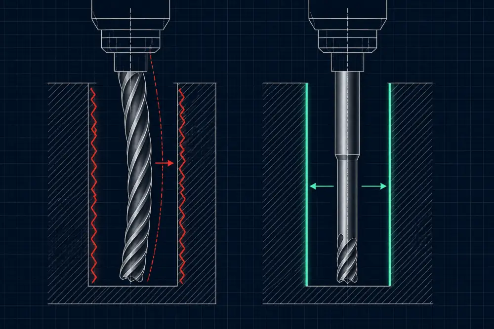
Deflection is proportional to the third power of the overhang length, meaning small extensions in tool reach significantly increase deflection:
Doubling tool overhang increases lateral deflection by a factor of eight under an identical radial cutting force. This dynamic causes dimensional wall taper, chatter marks, and tool fracture during deep cavity milling.
Relieved Neck Design vs Full-Flute Extended Cutters
A common error is purchasing tools with long continuous flute lengths (e.g., flute length equal to 5D or 6D) to clear deep pockets.
Continuous-flute tools suffer from two major mechanical weaknesses:
1. Compromised Web Diameter: Flutes require deep chip gullets along their entire length, reducing core cross-sectional mass and overall rigidity.
2. Excessive Radial Engagement Friction: The non-cutting peripheral edges rub against the finished pocket wall, introducing heavy side-load friction and heat, triggering low-frequency chatter.
To maximize stiffness in deep cavities, process planners should use stub-flute, neck-relieved cutters.
These tools feature a short cutting flute length (typically 1.5D to 2D) sufficient to clear the axial depth of cut per step-down pass. Above the flutes, the tool shank is ground down to a relieved neck diameter that is slightly smaller than the cutting diameter (typically 0.1 mm to 0.3 mm clearance per side).
Benefits demonstrated on the Dazao production floor:
· Over 60% Reduction in Tool Deflection: The thick, solid carbide tool shank extends deeper into the pocket cavity before transitioning to the relieved neck, preserving cross-sectional mass.
· Zero Wall Rubbing: The relieved zone provides mechanical clearance, eliminating rubbing, heat buildup, and chatter on deep vertical surfaces.
· Effective Deep Coolant Access: The neck relief gap allows high-pressure coolant or air blast to evacuate packed chips out of deep cavities smoothly.
Real-World Parameter Tuning: Beyond the Standard End Mill Speeds and Feeds Calculator
Online software programs provide useful baseline targets, but relying solely on an end mill speeds and feeds calculator without contextual tuning causes problems. Off-the-shelf calculators calculate feed rates assuming infinite structural rigidity, zero spindle runout, and steady cutting loads. Real CNC machine setups involve structural compliance that must be accounted for.
Machine Tool Interface Constraints: Spindle Taper Rigidity Thresholds
The maximum allowable material removal rate is constrained by the machine tool connection, directly influencing chatter frequencies frequently encountered in thin wall CNC machining operations:
· BT30 / HSK-E40 Spindles: High rotational acceleration, low static and dynamic rigidity. Using calculator outputs that call for heavy radial engagement in steels produces violent spindle stall and tool destruction. Tooling must be matched with high-speed, light-radial, deep-axial trochoidal strategies.
· BT40 / HSK-A63 Spindles: The production workhorse standard. Balances high-RPM dynamic milling with medium-duty roughing capability for tool diameters up to 16 mm (0.625 in).
· BT50 / HSK-A100 Spindles: Massive static stiffness and heavy low-RPM torque. Ideal for large-diameter roughing cutters, heavy slotting, and high-temp alloys where high radial cutting forces dominate.
Coolant Delivery and Thermal Cracking: Dry Air Blast vs Flood Coolant Shock
Flooding cutting zones with water-soluble coolant is standard practice, but it causes tool failures when misapplied during high-speed milling of ferrous and high-temp alloys; process engineers should refer to our engineering evaluation of CNC coolant types and delivery methods to prevent thermal shock.
Carbide substrates possess low thermal expansion and relatively high thermal conductivity, making them vulnerable to thermal shock. During high-speed trochoidal milling, a cutting tooth heats up past 750°C during engagement, then rapidly cools as it spins through the non-cutting arc.
Subjecting carbide to flood coolant creates extreme cyclical thermal stresses:
· Microscopic thermal stress fractures develop perpendicularly along the cutting edge.
· These micro-cracks coalesce into catastrophic edge chipping, destroying the cutter long before normal abrasive flank wear limits are reached.
Operational Rule: For high-speed dynamic milling of pre-hardened steels, stainless steels, and titanium, Dazao mandates high-pressure dry air blast or Minimum Quantity Lubrication (MQL). Air blast removes hot chips without subjecting cutting edges to thermal shock cycles. Flood coolant should be reserved for aluminum, copper, and slow-speed drilling/reaming operations.
Tooling Procurement Matrix: Standardized End Mill Size Chart and Factory Cost Standards
Standardizing tool crib inventory prevents machine operators from using mismatched tooling, reduces stock-outs, and cuts overall tooling expenditures.

Tool Crib Standardization and the Metric/Imperial Size Matrix
The following reference end mill size chart outlines standardized dimensions, core ratios, and typical depth capabilities for standard solid carbide configurations:
|
Nominal Cutting Diameter (mm / in) |
Standard Shank Diameter (mm / in) |
Flute Length (mm / in) |
Relieved Neck Diameter (mm / in) |
Relieved Reach Length (mm / in) |
Core Diameter (% of OD) |
Max Slotting Depth (ap) |
|
3.0 mm (0.118") |
6.0 mm (0.236") |
6.0 mm (0.236") |
2.80 mm (0.110") |
12.0 mm (0.472") |
55% |
1.0D |
|
6.0 mm (0.236") |
6.0 mm (0.236") |
13.0 mm (0.512") |
5.60 mm (0.220") |
24.0 mm (0.945") |
58% |
1.2D |
|
8.0 mm (0.315") |
8.0 mm (0.315") |
19.0 mm (0.748") |
7.50 mm (0.295") |
32.0 mm (1.260") |
60% |
1.5D |
|
10.0 mm (0.394") |
10.0 mm (0.394") |
22.0 mm (0.866") |
9.40 mm (0.370") |
40.0 mm (1.575") |
62% |
1.5D |
|
12.0 mm (0.472") |
12.0 mm (0.472") |
26.0 mm (1.024") |
11.30 mm (0.445") |
48.0 mm (1.890") |
62% |
1.5D |
|
16.0 mm (0.630") |
16.0 mm (0.630") |
32.0 mm (1.260") |
15.00 mm (0.590") |
64.0 mm (2.520") |
65% |
1.2D |
|
20.0 mm (0.787") |
20.0 mm (0.787") |
38.0 mm (1.496") |
19.00 mm (0.748") |
80.0 mm (3.150") |
65% |
1.0D |
The Economics of Regrinding vs Direct Tool Scrapping
Regrinding worn carbide tooling extends tool investment, but it carries economic trade-offs:
1. Dimensional Shrinkage: Regrinding the outer diameter reduces cutter size by 0.2 mm to 0.5 mm, while end-face grinding shortens overall length. These tools can no longer run production finish programs without manual tool-offset adjustments, increasing setup errors on automated production lines.
2. Economic Viability Threshold: Regrinding end mills with diameters below 10 mm (0.375 in) is rarely cost-effective. The inspection, logistics, and re-coating costs approach the price of new raw stock. Tools 12 mm and larger should be reground and recoated strictly for non-critical roughing passes.
The Dazao Factory Tooling Standards
To protect part quality across high-volume production, Dazao maintains three core shop floor standards:
· The 0.5 mm Bull-Nose Rule: True sharp square end mills are prohibited for roughing and semi-finishing. A minimum 0.5 mm corner radius is mandated across all structural programs.
· The Non-Ferrous Separation Rule: Uncoated or ZrN-coated cutters used for aluminum and copper are physically separated from steel-cutting tools to prevent cross-contamination and chip galling.
· Flank Wear Retirement Limits: Tools are retired or moved to roughing complying with standard criteria for CNC tool wear types and tool life monitoring before dimensional drift occurs, setting maximum flank wear at 0.15 mm.
Engineering Decision Funnel: Step-by-Step CNC Tooling Procurement Protocol
To ensure precision and profitability on every machining cycle, apply this 5-step decision workflow before releasing tooling purchase orders:
1. Material Identification: Classify the workpiece by hardness, abrasiveness, and ductility. For non-ferrous alloys, select uncoated polished carbide, ZrN, or DLC; for ferrous and hardened alloys, specify AlCrN, TiAlN, or TiSiN.
2. Feature Geometry Assessment: Identify internal corner fillets and floor transitions. Replace sharp square end mills with corner radius tooling wherever 90-degree internal edges are not explicitly required by drawing tolerances.
3. Flute and Core Balancing: Choose 2-flute configurations for deep, narrow aluminum slots; standardize on 3-flute polished designs for structural aluminum profiling; use 4-flute to 7-flute configurations for steels, stainless, and high-temp superalloys.
4. Reach-to-Diameter Calculation: Calculate overall overhang. If the depth exceeds 3 times the cutter diameter, avoid long continuous-flute tools and select a stub-flute cutter with a relieved neck.
5. Machine & Holder Matching: Align cutting loads with spindle taper capacity. Pair high-helix tooling with hydraulic or heat-shrink tool holders to prevent pull-out during dynamic cuts, or submit your engineering drawings for a direct DFM manufacturing review with our engineering department.

FAQs
01.Why does an end mill pull out of an ER collet during heavy roughing?
02.Why do TiAlN-coated end mills instantly weld when cutting 6061 aluminum?
03.Why does a ball nose end mill leave a rough, smeared finish on flat floors?
04.How do neck-relieved end mills eliminate tapered walls in deep pockets?
05.Why do sharp square end mills chip prematurely compared to corner radius end mills?
06.Why does flood coolant cause carbide chipping during high-speed trochoidal milling?





