


High speed machining is not merely running a spindle at 20000 RPM; it is a synchronized manufacturing methodology combining high surface speeds, shallow radial depth of cut, elevated feed rates, and constant tool engagement angles. True cycle time reduction requires matching CNC machine acceleration dynamics, toolholder balancing, and specialized CAM strategies to prevent tool rubbing, thermal buildup, and resonant chatter.
Demystifying High Speed Machining: Spindle RPM Myths, Shop Realities, and Thermal Physics
High speed machining is frequently misunderstood across the supply chain as a simple command to increase spindle speed to maximum levels. Early in the operation of the Dazao production facility, an attempt to cut cycle times on an aerospace batch by increasing a standard 3-flute carbide end mill from 8000 RPM to 24000 RPM on legacy linear paths resulted in immediate failure. Tool life dropped from 180 minutes to less than 12 minutes, severe chatter marks destroyed the surface finish beyond the target specification, and severe vibration damaged the ceramic spindle bearings.
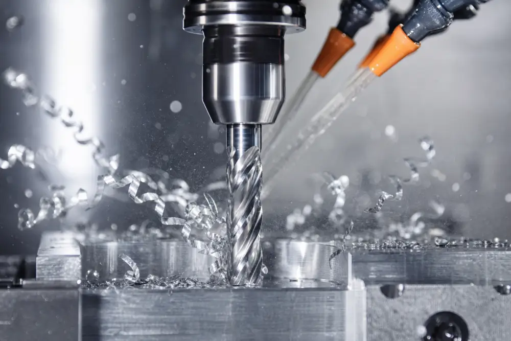
This workshop failure highlighted the physical foundation of high speed machining aluminum. True high-velocity processing relies on shifting mechanical cutting heat from the tool body and workpiece directly into the evacuated chip. When cutting speeds exceed specific metallurgical thresholds, plastic deformation occurs so rapidly that the workpiece material undergoes localized thermal softening along the primary shear zone.
To achieve this state without catastrophic cutter failure, the radial depth of cut must remain low (typically 5% to 20% of the cutter diameter) while the axial depth of cut is maximized. This mechanical profile reduces the radial engagement arc of each cutting flute, allowing the tool edge to cool during the non-cutting portion of its rotation. Understanding these thermal and dynamic relationships is as essential as studying a fundamental aluminum CNC machining guide when planning complex batch manufacturing.
|
Machining Strategy Parameter |
Conventional Milling Strategy |
High Speed Machining (HSM) Strategy |
|
Spindle Speed (RPM) |
4000 - 8000 RPM |
12000 - 35000 RPM |
|
Cutting Speed (Vc) for Al6061 |
150 - 300 m/min |
600 - 1800 m/min |
|
Radial Depth of Cut (ae) |
50% - 100% Cutter Diameter |
5% - 20% Cutter Diameter |
|
Axial Depth of Cut (ap) |
0.5x - 1.0x Cutter Diameter |
1.5x - 3.0x Cutter Diameter |
|
Tool Contact Arc |
90 - 180 Degrees |
15 - 45 Degrees |
|
Heat Distribution |
50% Workpiece / 30% Tool / 20% Chip |
10% Workpiece / 15% Tool / 75% Chip |
|
Primary Tool Failure Mode |
Abrasive Wear / Mechanical Overload |
Thermal Micro-Cracking / Centrifugal Runout |
Machine Dynamics and Feed Lag: Acceleration Limits in High Speed Machining Speeds and Feeds
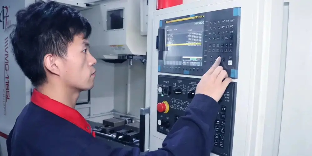
A common engineering error during process design is programming aggressive high speed machining speeds and feeds into CAM software without verifying the physical acceleration limits of the machine tool. A toolpath programmed for a feed rate of 10000 mm/min will rarely achieve that speed in complex pocketing contours if the machine axes have low linear acceleration, complicating the task of maintaining strict aluminum machining tolerances.
Controller Look-Ahead Starvation and the Friction-Rubbing Trap
Modern CNC machines rely on advanced look-ahead buffers (typically 500 to 2000 blocks) and jerk-limiting algorithms. When the toolpath approaches an internal corner or a tight radius, the motion controller decelerates the axes to prevent geometric overshooting.
If a machine is equipped with standard 0.3G axis drives, the controller begins braking well before the corner. The programmed feed rate of 8000 mm/min drops to an actual velocity under 1500 mm/min. When feed velocity collapses while the spindle maintains 20000 RPM, the effective advance per tooth drops below the minimum chip shearing threshold. Instead of shearing cleanly, the cutting flute rubs and burnishes the aluminum surface, causing rapid built-up edge formation, excessive heat accumulation, and edge micro-chipping.
Reliable high-speed processing requires matching high rotational speeds with machine platforms offering 1.0G to 2.0G linear acceleration.
|
Programmed Feed Rate |
Corner Radius (R) |
Machine Acceleration (G) |
Actual Velocity at Apex |
Actual Feed per Tooth (fz) |
Tool Status |
|
8000 mm/min |
R 5.0 mm |
0.3 G |
1750 mm/min |
0.029 mm/z |
Severe Rubbing / Built-Up Edge |
|
8000 mm/min |
R 5.0 mm |
1.0 G |
4200 mm/min |
0.070 mm/z |
Borderline Shearing |
|
8000 mm/min |
R 5.0 mm |
2.0 G |
7100 mm/min |
0.118 mm/z |
Clean Shearing / Stable HSM |
|
8000 mm/min |
R 1.5 mm |
0.3 G |
950 mm/min |
0.015 mm/z |
Immediate Tool Chipping |
|
8000 mm/min |
R 1.5 mm |
2.0 G |
3100 mm/min |
0.051 mm/z |
Moderate Rubbing / Micro-Wear |
Spindle Rigidity and Toolholding: Centrifugal Expansion and Runout in High Speed Machining Tool Life
Operating at rotational speeds above 15000 RPM introduces physical forces that destabilize conventional tooling assemblies. The dynamic performance of the toolholder directly dictates achievable high speed machining tool life.
Centrifugal Expansion at High Rotational Speeds
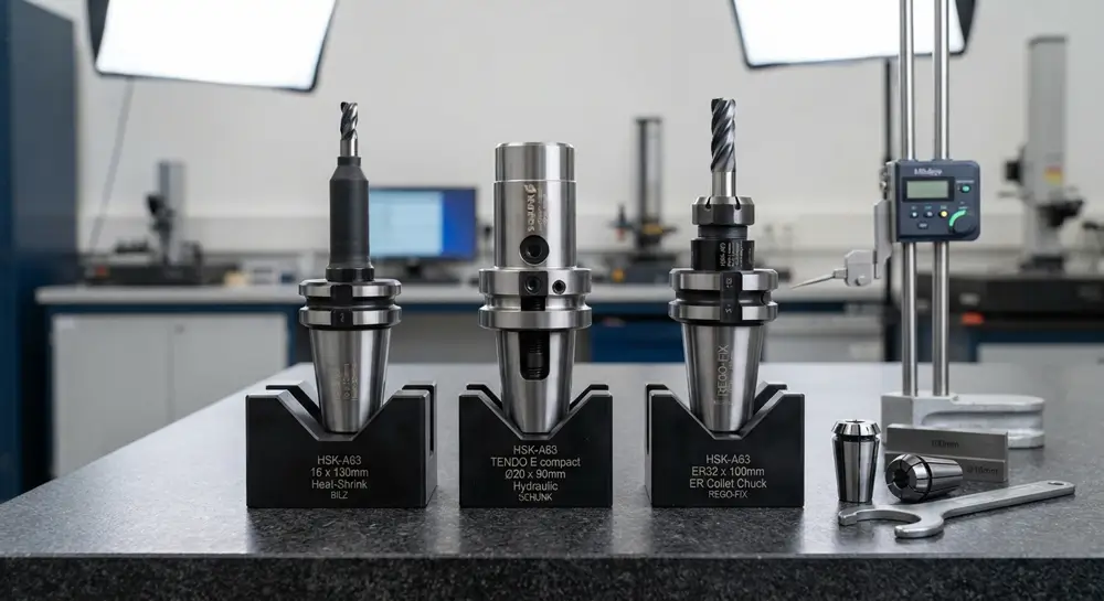
In standard steep-taper spindle interfaces such as standard BT40, the spindle taper expands radially under extreme centrifugal force. The solid steel toolholder taper does not expand at the same rate, causing the toolholder to seat deeper into the spindle. This axial displacement alters Z-axis repeatability and degrades taper-to-face contact rigidity.
Dual-contact spindle tooling systems and hollow-taper HSK-A interfaces resolve this mechanical issue. The hollow taper of an HSK holder expands in direct synchronization with the spindle taper, maintaining face and taper contact rigidity across rotational speeds up to 35000 RPM.
Toolholder Selection and Dynamic Balance
Standard ER collet chucks are unsuited for high speed aluminum operations. Asymmetric clamping nuts and multi-piece assemblies introduce dynamic unbalance and radial runout. A tool tip runout of merely 0.005 mm (5 microns) causes asymmetric tooth loading. At 24000 RPM, one flute absorbs the majority of the cutting impact, causing rapid edge degradation.
For all production CNC milling operations at Dazao, toolholders are standardized on heat-shrink and high-rigidity hydraulic chucks dynamically balanced to ISO 1940-1 Grade G2.5 at 25000 RPM.
|
Toolholder Type |
Radial Runout (at 3D) |
Clamping Force |
Vibration Damping |
Max Recommended RPM |
Tool Life Factor |
|
Standard ER32 Collet |
0.010 - 0.020 mm |
Moderate (60-80 Nm) |
Poor |
8000 RPM |
1.0x (Baseline) |
|
Precision ER (G2.5) |
0.005 - 0.008 mm |
Moderate (70-90 Nm) |
Fair |
15000 RPM |
1.4x |
|
High-Rigidity Hydraulic |
< 0.003 mm |
High (120-160 Nm) |
Excellent (Internal Fluid) |
24000 RPM |
2.2x |
|
Heat Shrink (HSK-A63) |
< 0.002 mm |
Extreme (200-300 Nm) |
Good (Symmetric Mass) |
35000+ RPM |
2.8x |
Microscopic Material Behavior: High Speed Aluminum Milling for 6061-T6 versus 7075-T6
The metallurgical characteristics of the workpiece govern shear mechanics and cutting parameters during high speed aluminum milling. Selecting cutting parameters requires cross-referencing the physical properties of our certified CNC materials to optimize spindle utilization.
Ductility versus Tensile Strength
Alloy 6061-T6 possesses high ductility and moderate yield strength (around 276 MPa). Under high surface speeds, 6061-T6 produces continuous, ductile chips that tend to weld to the cutter flutes if chip evacuation or cooling falters.
Conversely, 7075-T6 exhibits high zinc alloying and a yield strength exceeding 503 MPa. In high speed milling aluminum applications involving 7075-T6, the material shears with higher fracture toughness. While the risk of built-up edge is lower than with 6061, 7075-T6 imposes higher abrasive flank wear and requires greater dynamic rigidity from multi-axis kinematic configurations in 3-axis vs 5-axis CNC machining.
Radial Chip Thinning and True Chip Load Calculations
When the radial depth of cut (ae) is set below 50 percent of the tool diameter (D), the maximum chip thickness generated by the flute is geometrically smaller than the linear advance per tooth (fz).
Running a cutter at 10 percent radial engagement without feed compensation causes the flute to skim over the material without clean shear engagement. To maintain the targeted chip thickness (typically 0.10 mm to 0.18 mm per tooth for roughing), the programmed table feed rate must be compensated upward to prevent rubbing and premature tool wear.
|
Machining Parameter |
Al6061-T6 High Speed Roughing |
Al6061-T6 Finishing |
Al7075-T6 High Speed Roughing |
Al7075-T6 Finishing |
|
Tool Diameter (D) |
12.0 mm (3 Flutes) |
12.0 mm (3 Flutes) |
12.0 mm (3 Flutes) |
12.0 mm (3 Flutes) |
|
Surface Speed (Vc) |
900 m/min |
1200 m/min |
750 m/min |
1000 m/min |
|
Spindle Speed (n) |
23870 RPM |
31830 RPM |
19890 RPM |
26525 RPM |
|
Radial Engagement (ae) |
1.2 mm (10% D) |
0.3 mm (2.5% D) |
1.8 mm (15% D) |
0.3 mm (2.5% D) |
|
Axial Depth (ap) |
24.0 mm (2.0x D) |
24.0 mm (2.0x D) |
18.0 mm (1.5x D) |
24.0 mm (2.0x D) |
|
Programmed Feed per Tooth |
0.22 mm/tooth |
0.12 mm/tooth |
0.18 mm/tooth |
0.10 mm/tooth |
|
Table Feed Rate (Vf) |
15750 mm/min |
11450 mm/min |
10740 mm/min |
7950 mm/min |
|
Target Surface Roughness |
Ra 1.6 - 3.2 |
Ra 0.4 - 0.8 |
Ra 1.6 - 3.2 |
Ra 0.2 - 0.4 |
CAM Strategies: Adaptive Machining vs High Speed Machining Toolpaths
Understanding the operational boundaries of adaptive machining vs high speed machining is vital for reliable cycle time reduction when engineering deep CNC pockets and internal corner radii.
Constant Engagement Angle Mechanics
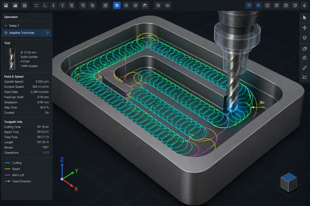
Traditional offset toolpaths maintain a constant stepover distance. When a cutter moves into a 90-degree corner, the tool engagement arc expands instantly from 45 degrees to 180 degrees. This sudden load surge causes severe tool deflection, vibration, and cutter breakage.
An adaptive high speed machining toolpath maintains an unvarying radial engagement angle (typically 30 to 45 degrees). CAM algorithms dynamically generate trochoidal loops and morphing spiral passes, narrowing the stepover as the tool approaches internal geometry to keep cutting forces balanced.
Eliminating Shock Entry and Air Cutting
High speed routines eliminate direct axial plunging. Plunging forces the non-cutting center web of an end mill into solid material, creating severe thrust forces. High speed toolpaths mandate smooth helical ramping (2 to 5 degrees) or pre-drilled pilot entries.
Furthermore, non-cutting transition passes are linked using high-feed micro-lifts (0.2 mm clearance at 15000 mm/min), preventing the tool from dragging across finished floors during repositioning.
Vibration and Deflection Control: High Speed Machining Thin Wall Aluminum and Deep Cavities
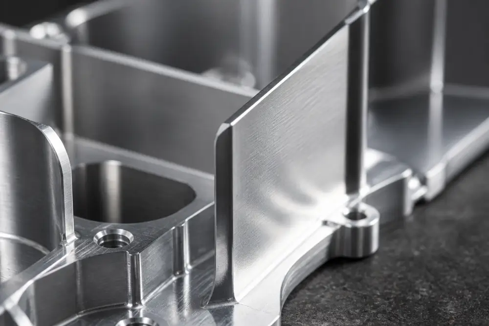
Machining lightweight aerospace ribs and electronics enclosures requires strict adherence to structural design rules for CNC wall thickness. In deep cavities, controlling high speed machining thin wall aluminum features presents distinct dynamic challenges.
Resonant Chatter and Wall Deflection
During deep pocket milling, high speed machining chatter occurs when the cutter tooth passing frequency matches the changing natural frequency of an unsupported thin wall.
As stock is progressively removed, the structural stiffness of the vertical rib drops. If the spindle speed remains fixed, self-excited regenerative chatter develops rapidly, leading to dimensional variation, wall waviness, and surface finish degradation.
Dazao Chatter Suppression Strategies
1. Synchronized Stepped Depth Toolpaths: The cutter alternates between adjacent pocket sides in shallow axial increments (0.5 mm to 1.0 mm), using the unmachined bulk stock on the opposite side as a rigid mechanical damper.
2. Unequal Pitch and Variable Helix End Mills: Three-flute cutters with variable helix angles (such as 38-degree, 41-degree, and 44-degree flutes) disrupt harmonic wave formation along the thin wall.
3. Dampening Fixtures: For thin floor webs and tall ribs under 0.8 mm thickness, custom vacuum fixtures, viscous dampening pads, or water-soluble rigid fixturing wax support the reverse side during final finishing passes.
4. Internal Residual Stress Release: Aggressive high-speed roughing releases rolling stresses unevenly. Dazao applies an initial roughing pass, unclamps the part to allow stress relaxation, and executes a final high-speed skim pass with balanced down-milling forces to prevent structural warpage.
Cutting Tool Geometry, DLC Coatings, and High-Pressure Chip Evacuation
High speed aluminum milling requires dedicated cutter geometries to maintain structural stability at elevated feed rates.
Substrate and Flute Geometry
Tool bodies should utilize sub-micron grain tungsten carbide (grain size 0.4 to 0.8 microns) with 6% to 8% cobalt content. Flutes must feature an open, mirror-polished surface finish (Ra below 0.1) and a high helix angle (40 to 45 degrees) to eject chips upward cleanly.
Coating Selection: Avoiding Titanium Aluminum Nitride
Applying standard TiAlN or AlTiN coatings when milling aluminum leads to rapid failure. The aluminum content within the coating exhibits high chemical affinity with the aluminum workpiece. Under localized cutting temperatures, chemical diffusion bonding occurs, welding chips directly to the tool rake face.
For high-speed aluminum processing, Dazao standardizes on:
· Uncoated Mirror-Polished Carbide: Highly economical for standard batches, offering zero chemical affinity with aluminum.
· Diamond-Like Carbon (DLC) Coatings: Extremely hard (over 5000 HV) with an ultra-low friction coefficient (under 0.1), preventing built-up edge and extending tool life in abrasive 7075-T6 stock. Post-machining part aesthetics can further be enhanced by following a specialized aluminum surface finishing guide.
Coolant Delivery Systems
Recutting chips is a primary cause of flute chipping. When chips fall back into a deep pocket, the cutter re-shears the aluminum fragments, doubling cutting forces. Dazao utilizes 70-bar through-spindle high-pressure coolant (TSC) to evacuate chips out of deep cavities instantly. For open aerospace ribs, Minimum Quantity Lubrication (MQL) delivers atomized alcohol-based lubricant directly to the shear zone.
High Speed CNC Machining Aerospace Economics: Cycle Time Analysis and Procurement Verification
While high speed milling delivers clear cycle time reductions, buyers must evaluate whether a specific part configuration justifies high-dynamic machine hourly rates when calculating custom aluminum CNC machining costs.
Adhering to comprehensive aluminum CNC design guidelines ensures that components fully benefit from high-speed toolpath strategies. For complex parts requiring both rotational and prismatic features, combining milling with dual-spindle CNC turning and mill-turn operations reduces cumulative setup errors.
Dazao Benchmark Case: Aerospace Structural Bracket
The following data reflects a verified production run at Dazao for a high speed CNC machining aerospace bracket manufactured from 7075-T6 billet stock (Initial size: 250 mm x 180 mm x 60 mm; Finished weight: 420 grams; Material removal ratio: 84%).
|
Performance Metric |
Conventional CNC Machining Process |
Dazao High Speed Machining Process |
Variance / Benefit |
|
Machine Platform |
Standard BT40 VMC (0.3G Accel, 8000 RPM) |
High-Dynamic HSK-A63 5-Axis (1.5G, 24000 RPM) |
Dynamic Response Upgrade |
|
Roughing Strategy |
Traditional Pocketing (ae 70%, ap 0.5D) |
Adaptive Dynamic HSM (ae 12%, ap 2.0D) |
Constant Tool Load |
|
Total Roughing Time |
42.5 minutes |
11.2 minutes |
73.6% Cycle Time Reduction |
|
Semi-Finish and Finish Time |
28.0 minutes |
9.5 minutes |
66.0% Cycle Time Reduction |
|
Total Part Cycle Time |
70.5 minutes |
20.7 minutes |
70.6% Net Time Savings |
|
Surface Finish Quality |
Ra 1.6 (Required Manual Polishing) |
Ra 0.4 (Direct Delivery Spec) |
Secondary Deburring Eliminated |
|
Tool Wear Cost per 100 Parts |
380 USD (Frequent Edge Chipping) |
145 USD (Consistent Wear Profile) |
61.8% Tooling Cost Reduction |
|
Total Unit Machining Cost |
92.00 USD |
54.50 USD |
40.7% Total Cost Reduction |
Procurement Checklist: Supplier Capability Verification
Before issuing production contracts for high-speed aluminum components, cross-reference your requirements against a standard pre-production CNC DFM checklist and verify the following technical points:
1. Machine Dynamics: Does the supplier operate machines with at least 1.0G acceleration and look-ahead capacity exceeding 500 blocks?
2. Spindle and Toolholding Rigidity: Are tools held in HSK or dual-contact holders balanced to G2.5 at maximum spindle speeds?
3. CAM Toolpathing: Does the programming team use constant-engagement adaptive toolpaths rather than legacy linear stepover offsets?
4. Thin-Wall Fixturing: What specific dampening and stress-relieving procedures are implemented for walls under 1.0 mm?
5. Inspection Capability: Does the supplier verify tight-tolerance features using calibrated CMMs and optical surface profilometers?

FAQs
01.Why do high-helix cutters pull out of standard ER collets during high speed aluminum milling?
02.What causes machine stuttering and edge burning during complex high speed toolpaths?
03.Why does TiAlN coating fail rapidly when high speed machining aluminum?
04.How do machinists stop thin vertical ribs from vibrating during high speed finish passes?
05.Why must feed rates be increased when running low radial depth of cut in HSM?
06.Is high speed machining cost-effective for single-piece prototype runs?





