


Pocket depths exceeding 4xD turn standard milling mechanics into an unstable cantilever deflection problem. At Dazao Machinery, maintaining wall perpendicularity within ±0.02 mm and Ra 0.8 surface finishes in deep cavities demands balanced radial chip loads, variable-helix long-reach end mills, hydraulic or shrink-fit holders to stop axial tool pull-out, and dynamic trochoidal toolpaths that lock radial engagement under 8%.
Deep Pocket CNC Machining Realities: Overcoming Aspect Ratio Bottlenecks Beyond 4xD
Why Aspect Ratios Over 4xD Break Conventional Machining Mechanics
In precision contract manufacturing, 2D engineering drawings frequently specify internal cavities with depth-to-width aspect ratios of 5:1, 8:1, or higher, matched with tight internal corner fillets of R2 or R3. Design engineers frequently assume that if a cutting tool possesses sufficient flute length, executing deep pocket milling requires nothing more than dividing the total depth into standard axial steps.
On the production floor, this assumption fails. Conventional milling mechanics function predictably when the tool overhang remains below three times the shank diameter (3xD). Once a job enters the domain of deep cavity milling strategies exceeding 4xD, standard cutting physics break down. Bending deflection increases non-linearly with tool extension, chip evacuation transitions from open ejection to pressurized containment, and resonant vibration thresholds compress the available stable parameters into narrow operating windows. Furthermore, tight internal fillets force small-diameter cutters to work at extreme extensions, which directly multiplies CNC corner radius machining cost factors due to cycle-time penalties.
|
Pocket Aspect Ratio |
Machining Stability Index |
Static Deflection Risk |
Cutting Velocity Derating |
Manufacturing Cost Multiplier |
|
< 3xD |
Stable (Nominal) |
Minimal (< 0.005 mm) |
100% (Baseline parameters) |
1.0x (Standard baseline) |
|
4xD - 5xD |
Moderate Vibration Risk |
Controlled (0.015 - 0.030 mm) |
70% - 80% of baseline |
1.6x - 2.2x |
|
6xD - 8xD |
Severe Instability |
High (0.040 - 0.090 mm) |
40% - 55% of baseline |
3.5x - 4.8x |
|
> 8xD |
Critical Resonance |
Extreme (> 0.120 mm) |
20% - 35% of baseline |
6.5x - 10.0x |
Shop-Floor Failure Analysis: The Scrapped Al7075 Aerospace Enclosure at Dazao
During an aerospace production run at Dazao Machinery, our team handled an Al7075-T651 avionics chassis requiring an internal rectangular pocket 110 mm deep, 45 mm wide, with 4.0 mm corner radii. This geometry created an aspect ratio exceeding 7xD for an 8 mm finishing end mill.
The initial CAM setup applied a conventional stepped-down contouring routine using a standard necked carbide end mill. Although the roughing cycle ran without tool breakage, post-machining CMM inspection revealed critical non-conformances:
1. The pocket side walls exhibited a 0.14 mm inward taper from top to bottom.
2. The bottom 35 mm of the pocket displayed severe regenerative chatter patterns, driving surface roughness past Ra 3.2, violating the required Ra 0.8 surface finish specification.
3. The sharp direction changes in the R4 corners caused local gouging of 0.08 mm due to dynamic tool deflection recovery.
The initial batch of 15 housings was rejected. Our post-mortem analysis revealed that tool deflection was not the sole cause. Chip recutting at the cavity floor had generated localized thermal buildup, causing the workpiece to expand during roughing. When the part cooled to 20°C on the CMM, the bottom contracted inward, compounding the geometric error caused by tool deflection. Managing these combined thermal and dynamic factors is essential to maintain tight aluminum CNC machining tolerance capabilities across complex aerospace housings. Dazao re-engineered the process with balanced trochoidal toolpaths, dynamic air purging, and a multi-stage tool-reach sequence, bringing the wall perpendicularity within ±0.015 mm.
Procurement Checklist: Auditing Shop-Floor Capabilities for Deep Cavity Milling Strategies
When procurement teams evaluate machine shops for components featuring deep cavities, checking equipment lists for high-speed spindles is insufficient. Delivering precision deep pockets requires verifiable operational capabilities:
· Toolholder infrastructure: Complete deployment of shrink-fit or hydraulic clamping with assembly runout under 0.003 mm at 3xD overhang, rather than general-purpose ER collet chucks.
· CAM software capabilities: Native dynamic motion generation that maintains constant radial engagement angles through internal corners.
· In-process metrology: High-precision contact probing systems programmed to inspect intermediate stock allowances before committing long-reach finishing tools to final passes.
· Specialized production services: Verifying that a supplier delivers high-precision CNC machining services equipped with vibration-damped tooling and high-pressure through-spindle capabilities.
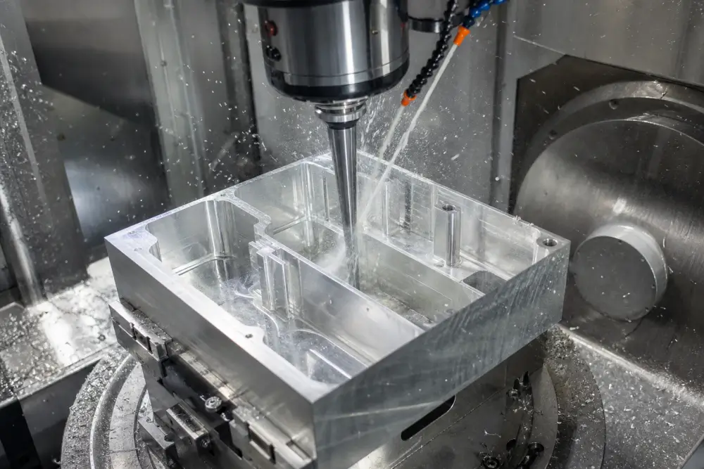
The Physics of Deep Pocket Milling Tool Deflection: Preventing Tapered Walls and Dimensional Drift
The Cantilever Stiffness Penalty: Why Doubling Tool Overhang Decreases Rigidity Eightfold
The primary limiting factor in deep pocket milling tool deflection is cantilever bending mechanics. In end milling, the tool behaves as an unsupported beam anchored at the toolholder collet nose and subjected to point loading at the cutting tip.
The bending deflection of an end mill increases in direct proportion to the radial cutting force and the cube of the unsupported overhang length. In contrast, tool rigidity scales with the fourth power of the tool core diameter and the elastic modulus of the material.
When a machinist increases tool overhang from 3xD to 6xD to access a deeper cavity floor, doubling that unsupported length reduces structural stiffness by a factor of eight. Tripling the overhang to 9xD reduces stiffness by a factor of twenty-seven. Because solid carbide possesses an elastic modulus of approximately 550 to 650 GPa (nearly three times that of standard tool steel), solid carbide shanks are mandatory. However, even solid carbide deflects under modest cutting forces once overhang extends past 50 mm. A radial cutting force of merely 120 N acting on an 8 mm carbide end mill with an 80 mm overhang produces a theoretical tip deflection exceeding 0.06 mm, sufficient to breach aerospace and medical tolerances instantly.
Critical Geometric Defects: Inward Wall Taper, Bell-Mouth Openings, and Corner Elastic Spring-Back
Tool deflection manifests in distinct geometric part defects:
· Tapered Cavity Walls: As an end mill steps down into the cavity, cumulative side pressure forces the cutter away from the intended wall vector. The top of the pocket, machined with shorter tool extensions or supported by stiffer shank sections, meets nominal dimensions. The bottom narrows progressively, creating an inverted taper.
· Bell-Mouth Openings: If a long-reach tool enters the pocket using a standard linear plunge or aggressive ramp, initial entry deflection kicks the tool outward, over-cutting the pocket mouth before stabilizing at depth.
· Corner Radius Over-Cutting: As the cutter tracks into an internal 90-degree corner, the tool engagement angle jumps from 15 degrees on a straight wall to 90 degrees or more in the corner. The sudden surge in radial force pushes the cutter off its path. As the tool exits the corner, the stored elastic energy releases, causing the cutter to spring back into the material and gouge the adjacent wall.
The CAM Simulation Trap: Tool Neck Deflection Rubbing and Side-Wall Work-Hardening
A frequent pitfall in deep pocket CNC machining involves blind reliance on standard CAM collision simulations. CAM software treats cutting tools and toolholders as perfectly rigid bodies. If the programmer specifies a neck-relieved end mill with a 0.25 mm radial clearance per side, the computer model confirms zero interference between the tool neck and the pocket wall.
In actual production, radial cutting forces flex the tool tip by 0.05 mm to 0.10 mm. This flexure tilts the entire tool axis inside the cavity. Consequently, the relieved cylindrical neck of the cutter makes physical contact with the semi-finished sidewall behind the cutting zone.
In materials like Al6061-T6 and Al7075-T651, this continuous high-speed rubbing creates intense frictional heat and burns the aluminum surface, causing severe localized work-hardening. When a secondary fine-finishing end mill engages that wall, it encounters a burnished, strain-hardened material band. The finishing cutter chatters, rubs, suffers micro-chipping along its peripheral edges, and leaves visible witness marks that compromise compliance with required precision CNC surface finishing standards and violate profile tolerances.
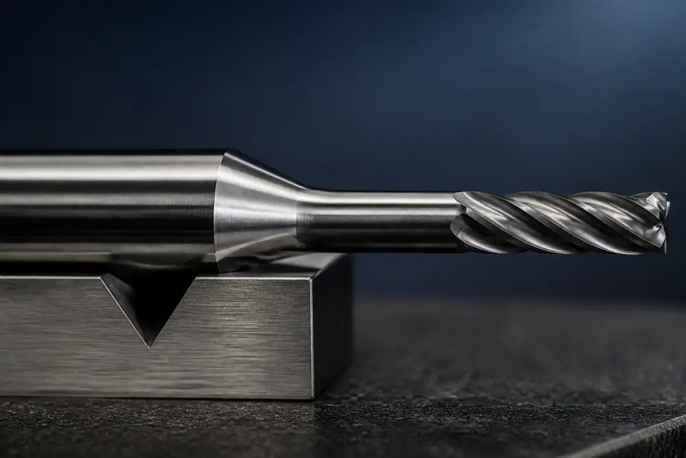
Suppressing Deep Pocket Milling Chatter: Resonance Control and Toolholding Selection
Regenerative Chatter Mechanics: The Dangers of Low Feed-Per-Tooth Burnishing
The onset of deep pocket milling chatter is a self-exciting dynamic instability. As the cutter rotates, each cutting flute removes a chip whose thickness is modulated by the vibration ripples left on the surface by the preceding flute.
If the phase shift between the inner surface wave and the outer surface wave aligns with the natural resonant frequency of the tool-toolholder-spindle assembly, vibration amplifies exponentially. In deep cavities, where long overhang significantly lowers the natural frequency of the tool assembly, this stability boundary drops. The result is rapid chatter onset, characterized by loud acoustic squeals, faceted wall finishes, and catastrophic edge breakdown.
A common error made by machine operators attempting to suppress chatter is drastically reducing the feed rate per tooth while maintaining high spindle speeds. When the feed per tooth drops below the hone radius of the cutting edge (typically 0.005 mm to 0.012 mm on polished aluminum tools), the cutter ceases shearing cleanly. Instead, the edge burnishes and plows the substrate. This plowing action increases radial forces, driving the flexible assembly directly into regenerative resonance.
Asymmetric Cutter Geometries: Selecting Long Reach End Mills for Deep Pockets
To machine deep pockets reliably, shops must replace standard symmetrical end mills with application-specific tooling like a long reach end mill deep pocket cutter:
· Variable Helix Angles: Tools featuring flutes configured at alternating angles (for instance, 38 degrees on flute one and 41 degrees on flute two) continuously alter the axial chip shear angle. This breaks the constant phase relationship of cutting forces, disrupting the regeneration of surface waves.
· Variable Flute Indexing: Unequal circumferential spacing between flutes (such as spacing of 88° - 92° - 89° - 91° instead of a standard 90° separation) prevents the tool from establishing a uniform impact frequency against the cavity wall.
· Tapered Core Geometry: Specialized long-reach end mills incorporating a back-tapered core increase cross-sectional stiffness toward the shank, yielding up to 35% higher dynamic rigidity than constant-cross-section necked tools.
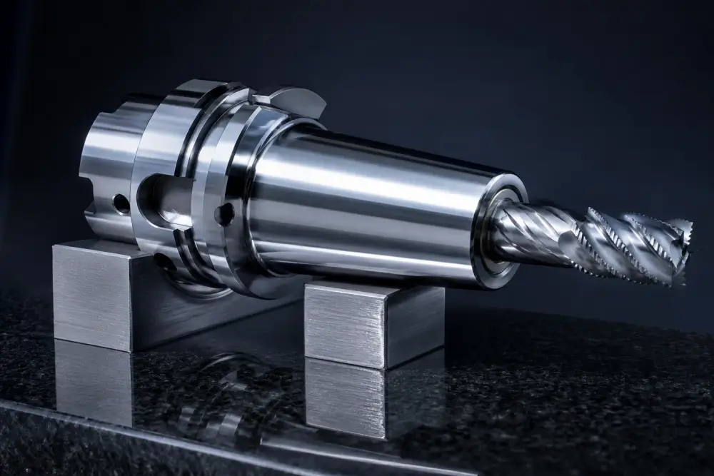
The Collet Creep Hazard: Micro-Fretting and Catastrophic Axial Tool Pull-Out Under Harmonic Vibration
One of the most destructive failure modes in deep pocket operations involves tool pull-out from the clamping system.
When executing aggressive roughing passes in aluminum cavities using high-helix cutters (45 degrees to 55 degrees), the geometry generates high axial downward cutting forces that physically pull the tool toward the bottom of the pocket. In deep cavities, this steady downward pull combines with severe, high-frequency lateral chatter vibrations.
Standard ER collet chucks rely entirely on mechanical friction distributed over a split-sleeve cone. Under sustained lateral vibration, micro-fretting occurs at the collet-to-tool-shank interface. The microscopic relative motion degrades the clamping contact pressure. Over several minutes of continuous milling, the end mill slowly creeps out of the collet along the Z-axis by 0.08 mm to 0.35 mm.
Because tool extension occurs gradually inside a blind cavity, the machine control cannot detect the shift until the cutter contacts the cavity floor during a rapid transit or finishes the bottom face severely undersize, scrapping the workpiece. To eliminate this risk, shops must transition to rigid clamping systems:
|
Toolholding System Type |
Radial Runout at 3xD Overhang |
Clamping Torque / Retention |
Vibration Damping Capacity |
Tool Pull-Out Risk Under Chatter |
Suitable for Deep Pocket Roughing |
|
Standard ER Collet (ER32/ER40) |
0.010 mm - 0.015 mm |
Moderate (Friction only) |
Low |
High (Micro-fretting slip) |
No (Prohibited > 4xD) |
|
Precision ER Collet (Single-Piece Nut) |
0.005 mm - 0.008 mm |
Moderate to High |
Low to Moderate |
Moderate |
Limited (Finishing only) |
|
Hydraulic Expansion Chuck |
< 0.003 mm |
High (Uniform hydraulic oil film) |
Superior (High dynamic damping) |
Low |
Yes (Light to Medium cuts) |
|
Induction Shrink-Fit Holder |
< 0.003 mm |
Extreme (Thermal interference fit) |
Low to Moderate |
Low to Moderate |
Yes (High-speed finishing) |
|
Positive Mechanical Lock (Safe-Lock) |
< 0.003 mm |
Extreme (Drive keys + Shrink/Hydraulic) |
High |
Zero (Mechanically locked) |
Yes (Mandatory for heavy roughing) |
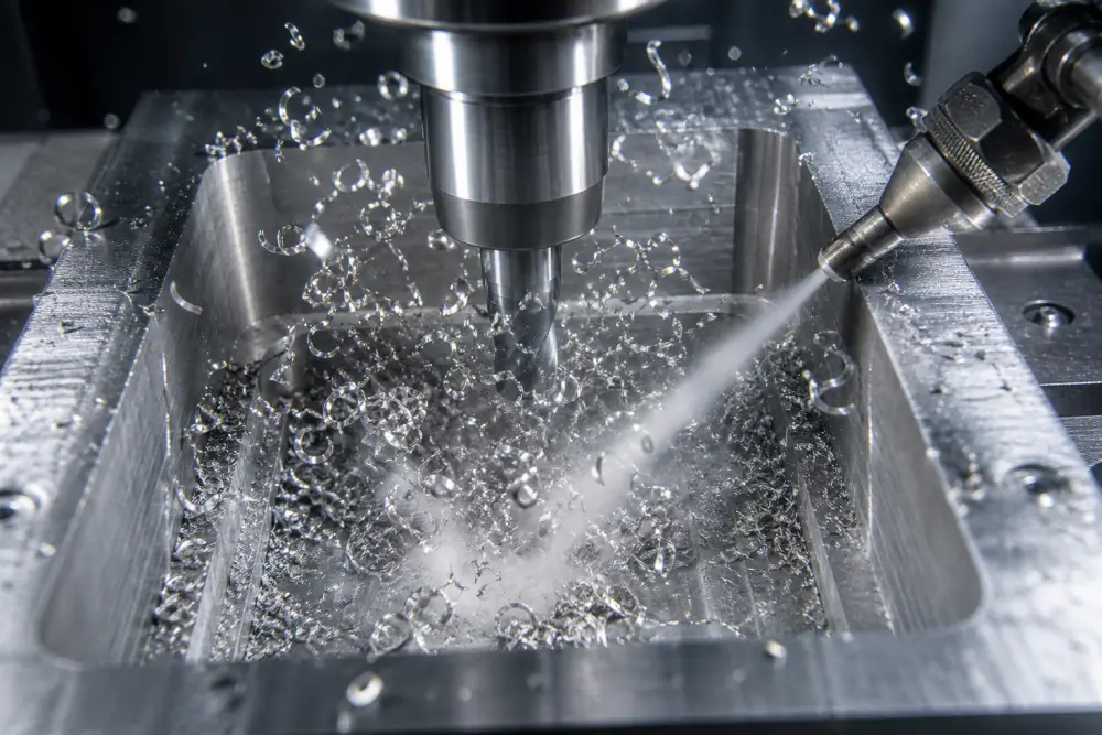
Blind Cavity Chip Evacuation and Thermal Control: Eliminating Chip Recutting
The Impact of Chip Recutting: Force Spikes, Micro-Chipping, and Surface Tearing
In deep cavity operations, successful execution depends entirely on clean deep pocket chip evacuation. In standard shoulder or face milling, kinetic energy flings chips clear of the toolpath. In a deep blind pocket, the side walls turn the cavity into an enclosed containment vessel where gravity and turbulent boundary-layer air resistance trap chips at the pocket floor.
When chips fail to evacuate immediately, rotating flute faces drag those severed metal segments back through the shear zone. This chip recutting triggers rapid system degradation:
· Radial cutting force spikes dynamically by 200% to 400% as the flute wedges an existing chip against solid parent material.
· The cutting edge chips at the micro-scale, accelerating flank wear and destroying polished rake faces.
· Fragmented, compacted chips score the finished side walls, driving surface roughness well past acceptable limits.
· Spikes in mechanical resistance generate localized heat, causing aluminum chips to weld directly into the tool flutes, resulting in catastrophic tool breakage within fractions of a second.
Ductility and Swarf Packing: Best Practices for Deep Pocket Milling Aluminum
Executing deep pocket milling aluminum requires specialized approaches due to the high ductility and thermal expansion coefficients of alloys such as Al6061-T6 and Al7075-T651. When cutting deep features into structural billets, following proven aluminum CNC machining techniques ensures long-strand swarf does not clog the flutes.
Unlike cast iron or hardened tool steels that yield small, segmented chips, aluminum alloys produce continuous, ductile ribbons under non-optimized chip loads. Inside a deep cavity, these continuous ribbons wrap around the tool body in a failure mode known as bird-nesting. Once a bird-nest forms:
1. It blocks the entry of cutting fluids or compressed air into the active cutting zone.
2. It scours the pocket walls, leaving deep circular gouges.
3. The rotating mass of swarf increases rotational imbalance at the tool tip, triggering severe chatter.
To prevent this, tooling must utilize razor-sharp cutting edges ground with high positive rake angles (15° to 22°), polished flutes with surface roughness below Ra 0.1, and chip-breaker notches along the peripheral cutting edge. These geometries mechanically break ductile aluminum chips into tightly curled needles that clear the cavity without packing.
Coolant Delivery Showdown: High-Pressure Flood vs. Through-Spindle Air Blast Purging
Selecting the proper fluid delivery method is vital for reliable evacuation:
· Standard External Flood Coolant: Often counterproductive in deep cavities. The high-speed rotation of the tool creates a centrifugal air barrier that deflects low-pressure coolant streams away from the cutting tip. Furthermore, external coolant can wash chips downward into the bottom corners, forming an abrasive metallic slurry.
· Through-Spindle High-Pressure Air (6 to 10 Bar): The most reliable method for dry or near-dry aluminum roughing. The continuous axial air stream pressurizes the cavity floor, blowing chips straight up and out through the open top of the pocket.
· Through-Tool Minimum Quantity Lubrication (MQL): Delivers aerosolized vegetable oil micro-droplets directly to the tool-chip interface at the bottom of the cut. This eliminates thermal shock, prevents chip adhesion, and maintains clear evacuation channels without pooling fluid in the pocket floor.
The Cavity Floor Vortex Trap and Thermal Expansion Distortion in Long Roughing Cycles
In production environments, two subtle variables often lead to scrapped parts:
The Hydraulic Vortex Trap: When machinists apply high-pressure flood coolant (30 to 70 Bar) straight down into a deep blind cavity, the fluid impacts the pocket floor and forms a high-velocity hydraulic vortex. This vortex creates a low-pressure dead zone directly behind the cutting tool, trapping fine chips and rotating them in a closed loop. The trapped swarf repeatedly strikes the cavity bottom, creating a sandblasted, pitted finish. Dazao Machinery eliminates this issue by using pulsing through-spindle air or angled high-pressure coolant nozzles that establish a unidirectional fluid exit path up one side of the cavity wall.
Thermal Growth Inversion During Roughing: Deep pocket roughing cycles often run continuously for 30 to 90 minutes per part. The friction generated by high-rate material removal conducts directly into the raw billet. In a thick aluminum plate, internal cavity temperatures can rise to 65°C to 80°C, causing the bottom of the component to expand upward and outward.
If an operator performs in-process probing on the hot part, the dimensions may appear nominal. Once the part unclamps, cools to a standard 20°C inspection temperature, and stabilizes, thermal contraction pulls the pocket floor upward and contracts the bottom side walls inward. The resulting cavity displays an out-of-spec negative tolerance.
Dazao's deep pocket protocol enforces a mandatory roughing-to-finishing thermal stabilization hold. After bulk metal removal, parts undergo a 45-minute coolant rinse and soak cycle, bringing the substrate to thermal equilibrium before executing final finishing passes.
Advanced Deep Pocket Milling Toolpaths: Dynamic Roughing to High-Precision Finishing
Why Conventional Pocket Clearing Causes Catastrophic Tool Failure in Corners
Traditional CAM toolpaths, such as directional rastering and linear offset contouring, fail in deep pockets. In a standard offset toolpath, the cutter follows the contour of the pocket inward. When the tool encounters an internal corner, the radial width of cut spikes instantly. Programming toolpaths for extreme depths requires shifting from legacy routines to dedicated engineering guidelines for CNC pocket design optimized for chip evacuation.
On a straight wall, an end mill might run at an intended 10% radial immersion (a 36-degree contact arc). In a sharp 90-degree corner, the tool engagement angle jumps instantly to 180 degrees. For a short-reach tool, this causes momentary spindle load spikes; for a long-reach end mill with an overhang exceeding 5xD, this load surge causes immediate deflection, chatter, or tool breakage.
Dynamic Trochoidal Milling: Maintaining Constant Radial Engagement Angles Below 10%
Implementing high-performance deep pocket milling toolpath strategies relies entirely on dynamic, constant-engagement motion. Applying dynamic trochoidal toolpaths relies on modern high-speed machining aluminum practices to keep spindle loads constant across complex profiles.
· Constant Tool Engagement Angle (TEA): Advanced CAM algorithms calculate continuous spiral and trochoidal tool movements that cap radial engagement at a fixed value (typically 6% to 10% of the cutter diameter). As the tool enters corners, the path automatically tightens its loop radius, preventing force spikes.
· Maximum Axial Depth, Minimum Radial Width: Instead of taking multiple shallow axial cuts with heavy radial engagement, dynamic milling inverts the strategy. Machinists use a large axial depth of cut (up to 2xD to 3xD) paired with a small radial engagement width (ae between 5% and 8%).
· Chip Thinning Compensation: Because radial engagement remains below 10%, the cut produces thin chips. To maintain the intended chip thickness and avoid edge burnishing, programmers must scale up the programmed feed rate. This sustains efficient chip shearing while keeping radial push forces low enough to prevent cantilever deflection.
Progressive Rest-Roughing: Dazao Multi-Tiered Tool Reach Sequence
Attempting to rough a deep cavity using a single long-reach cutter wastes production time and increases failure risk. Mastering modern deep pocket milling techniques requires applying a rigid multi-stage tool reach sequence for cavities deeper than 50 mm:
1. Stage 1: Primary Bulk Hogging: Run a large-diameter, short-reach indexable insert cutter or solid carbide rougher (e.g., 20 mm or 25 mm diameter) held at minimum extension (under 2.5xD). This tool aggressively clears 60% to 70% of the internal volume from the top of the pocket down to its mechanical interference limit.
2. Stage 2: Stepped Intermediate Rest-Roughing: Introduce an intermediate-reach tool (e.g., 16 mm diameter at 4xD overhang) to step down the remaining stock, followed by a necked-down rougher to machine the lower core. The tool processes only the residual steps left by Stage 1, protecting the cutter from full-slotting forces.
3. Stage 3: Deep Corner Rest-Clearing: Deploy a dedicated long-reach cutter matching the final corner fillet radius. This tool clears the corner rest material using high-speed trochoidal passes, leaving a uniform finish allowance along all walls and floors.
Sidewall Stock Allocation: The Precise Window Between Tool Rubbing and Tool Deflection
Finishing a deep pocket sidewall requires a precise radial stock allowance. Leaving too much stock causes long-reach finishing tools to deflect away from the wall; leaving too little causes the edge to rub and work-harden the surface.
|
Tool Overhang Ratio |
Recommended Radial Finishing Stock (ae) |
Axial Stepdown for Finishing (ap) |
Primary Finishing Objective |
|
3xD to 4xD |
0.12 mm - 0.18 mm |
Full pocket depth (single pass) |
Eliminates horizontal blend lines |
|
5xD to 6xD |
0.08 mm - 0.12 mm |
0.5x to 1.0x Tool Diameter |
Limits tool push-off and bottom taper |
|
7xD to 8xD |
0.04 mm - 0.06 mm |
0.25x to 0.5x Tool Diameter |
Suppresses regenerative chatter |
|
> 8xD |
0.03 mm - 0.05 mm (Double finish pass) |
Spring pass + Final sizing pass |
Compensates for elastic tool deflection |
Machine Architecture: 3-Axis Vertical Limits vs. 5-Axis Tilted Deep Cavity Machining
The Rigidity Ceiling of 3-Axis Machining: Excessive Tool Overhang and Reduced Feed Rates
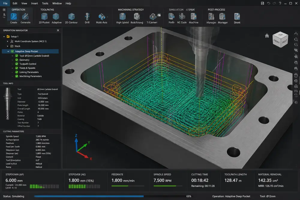
On a standard 3-axis vertical machining center (VMC), the cutting tool axis remains strictly parallel to the vertical Z-axis. To reach the floor of a 120 mm deep pocket, the entire length of the cutter and its neck extension must measure at least 120 mm plus clearance.
This mechanical constraint forces the use of extreme tool extensions, drastically reducing operational rigidity. Feed rates must be scaled back by up to 70%, tool cycle times multiply, and the risk of catastrophic chatter remains high throughout the operation.
5-Axis Tilted Toolpath Advantages: Eliminating Tool Reach Deflection and Tripling Metal Removal
Transferring deep cavity components to 5-axis machining centers fundamentally alters the process physics. Evaluating the mechanical performance metrics in our 3-axis vs 5-axis CNC machining comparison demonstrates why tilting the spindle cuts cycle times in half.
Using 3+2 positional machining or full 5-axis simultaneous motion, the machine tilts the workpiece or spindle head by 15 to 30 degrees relative to the tool axis:
· Tool Overhang Reduction: Tilting allows the toolholder assembly to clear the top rim of the pocket. The machinist can run a short, rigid stubby end mill (overhang under 3xD) to cut features that would otherwise require an 8xD tool on a 3-axis machine.
· Point-Contact Milling: Tilting prevents the zero-surface-speed center dead spot of ball nose cutters from contacting the workpiece floor, shifting the contact zone to the high-efficiency peripheral cutting edge.
· Cycle Time Reduction: Because the short tool maintains high dynamic stiffness, cutting speeds and chip loads can run at three to four times the parameters of a long-reach tool, reducing overall cavity cycle time by 45% to 60%.
|
Machining Performance Metric |
3-Axis Setup (Long Overhang Tool: 8xD) |
5-Axis Tilted Setup (Short Stubby Tool: 2.5xD) |
Performance Impact (5-Axis vs 3-Axis) |
|
Bending Rigidity |
Baseline (1.0x - Highly Flexible) |
~32.8x higher static stiffness |
97% reduction in tip deflection |
|
Maximum Stable Feed Rate |
600 - 900 mm/min |
2,800 - 4,200 mm/min |
350% to 450% higher feed velocity |
|
Achievable Sidewall Finish |
Ra 1.6 - Ra 3.2 (Chatter prone) |
Ra 0.4 - Ra 0.8 (Consistent shear) |
Significant improvement in surface finish |
|
Tool Life per Cutting Edge |
12 - 25 minutes (Accelerated wear) |
80 - 150 minutes |
500% to 600% extension in tool life |
|
Part Cycle Time (Rough to Finish) |
145 minutes |
58 minutes |
60% total cycle time reduction |
Part Fixturing Dynamics: Damping Thin-Wall Pocket Resonance with Custom Jaws and Fillers
When deep cavities are combined with thin external or internal structural walls (e.g., wall thicknesses below 2.0 mm), cutting force excitation transfers into the workpiece itself. The thin wall behaves like an unconstrained plate, vibrating independently and producing chatter marks even when using rigid, short tooling. To stop harmonic vibration from flexing unsupported cavity ribs, review our CNC wall thickness design recommendations to balance weight and rigidity.
Dazao Machinery applies dedicated resonance damping techniques for thin-walled deep cavity milling:
· Elastomeric Damping Vices: Machining fixtures utilize custom polyurethane-lined jaws that support the exterior profile of the component, dampening acoustic frequencies during interior pocketing.
· Temporary Structural Fillers: For extreme aspect ratios, cavities are backfilled with water-soluble structural polymers or low-melting-point bismuth alloys. These fillers solidify behind thin walls during roughing, converting flexible membranes into rigid solid blocks. Once machining concludes, the filler melts away cleanly in hot water baths at 80°C without leaving chemical residues or altering metal temper.
DFM Guidelines and Sourcing Strategy: Balancing Cavity Depth, Tolerances, and Machining Costs
Design-for-Manufacturability Protocols: Corner Radii, Wall Draft, and Split Modular Designs
To control manufacturing costs, design engineers should incorporate three core design-for-manufacturability rules into early CAD models. Incorporating established aluminum CNC machining design rules during early CAD modeling prevents impossible tool access conditions. Furthermore, design teams should run internal cavity designs through a structured CNC DFM checklist for production parts before releasing final 2D prints.
1. Corner Radius Sizing: Never design an internal corner radius equal to a standard tool radius (e.g., an R5.0 mm corner machined with a 10 mm end mill). Always specify corner radii at least 15% to 20% larger than the intended cutter radius (e.g., specify R6.0 mm or R6.5 mm for a 10 mm tool). This permits CAM toolpaths to roll smoothly through the corner without coming to an abrupt stop or increasing tool engagement.
2. Draft Angles on Deep Sidewalls: Adding even a 0.5-degree to 1.5-degree draft angle to deep cavity side walls provides natural clearance for cutter shanks and toolholder bodies. This simple feature permits the use of conical, high-rigidity end mills that deliver up to four times the bending stiffness of straight-shank tools.
3. Internal Relief Grooves and Floor Chamfers: Where walls meet the pocket floor, incorporating a 0.5 mm undercut or radius prevents the extreme tip of the cutter from engaging simultaneously on the bottom and the side wall, lowering corner cutting forces.
Sourcing Cost Curves: The Exponential Cost Multipliers of Deep Aspect Ratios
Procurement teams must recognize that deep cavity manufacturing costs scale non-linearly with depth. Understanding how extreme depth drives exponential cycle times is central to evaluating an accurate aluminum CNC machining cost analysis for complex enclosures.
Between 1xD and 3xD, material removal rates remain high and standard tools run at peak feed rates, establishing the baseline unit cost. Crossing the 4xD threshold necessitates specialized long-reach tooling, lower feeds, and multi-stage machining cycles, which doubles base operational costs. Once cavity depth exceeds 8xD, production demands 5-axis machine time, custom tool assemblies, and mandatory in-process stabilization steps, raising final part costs by three to six times standard baseline milling.
|
Cavity Aspect Ratio |
Operational Tooling Required |
Primary Machining Strategy |
Relative Production Cost Level |
|
Depth < 3xD |
Standard solid carbide end mills |
High-speed conventional roughing |
Baseline unit cost |
|
Depth 4xD - 6xD |
Necked-down variable-helix cutters |
Dynamic trochoidal rest-milling |
Approximately 2.0x to 2.5x baseline |
|
Depth > 8xD |
Shrink-fit long reach or 5-axis tooling |
5-Axis tilted roughing plus CMM holds |
Up to 4.0x to 6.0x baseline |
Quality Assurance at Dazao: In-Process Probing, Thermal Soak Holds, and Zeiss CMM Validation
To guarantee dimensional compliance on complex deep pocket geometries, Dazao Machinery enforces a four-stage quality verification process:
· CAD/CAM Model Stress Review: Automated kinematic collision checking and tool deflection simulations identify clearance issues prior to production setup.
· Tool Preset Laser Inspection: Offline optical tool presetters verify runout across all cutter flutes, holding assembly runout under 0.003 mm.
· On-Machine High-Precision Probing: Workpiece features undergo intermediate inspection cycles before executing finish passes, tracking stock allowances and detecting thermal drift.
· Post-Machining CMM Validation: Final inspection on Zeiss coordinate measuring machines operating in climate-controlled quality laboratories (20°C ± 0.5°C) delivers certified CMM quality inspection and geometric verification, capturing full 3D point-cloud data for wall perpendicularity, true position, and profile compliance.

FAQs
01.Why does an end mill pull out of an ER collet during deep pocket roughing?
02.Why does flood coolant cause tool chipping in deep blind cavities?
03.Why do long-reach cutters vibrate violently in cavity corners during pocketing?
04.Why does a spring pass fail to eliminate taper on deep pocket side walls?
05.How do shops prevent cutter spring-back gouges on the pocket floor?
06.When should a design engineer split a deep pocket into a modular assembly?





