


Micro CNC machining is governed by contact mechanics and plowing dynamics rather than macroscopic shear removal. When tool diameters drop below 1.0 mm, cutting edge hone radii compete directly with chip thickness, creating severe elastic deflection and material burnishing. Producing consistent features within ±0.002 mm tolerances demands total indicator runout under 1 micron, aggressive minimum chip load programming to bypass strain hardening, non-destructive megasonic post-processing, and strict cleanroom thermal equilibrium during optical metrology.
Micro CNC Machining Engineering Guide: Sub-Millimeter Tolerances, Burr Eradication, and Optical Metrology
Scaling engineered components down into the sub-millimeter spectrum introduces physical barriers that invalidate standard manufacturing assumptions. Industrial buyers looking for dependable micro machining services frequently treat sub-millimeter fabrication as conventional milling executed with smaller cutters. At Dazao, our manufacturing history across automotive, semiconductor, medical, and aerospace accounts proves that miniature geometries operate under completely transformed cutting physics.
Executing micro CNC machining demands an engineering framework where conventional shear models give way to elastoplastic deformation, surface plowing, and severe micro-deflection. Whether your team is specifying micro-fluidic channels, optic sensor brackets, or miniature mechanical linkages, achieving tight micro machining tolerances requires rigorous control over spindle dynamics, grain boundaries, and metrology drift. When procuring high-precision custom CNC machining services for sub-millimeter components, sourcing teams must look beyond nominal spindle speed and evaluate actual dynamic stability.
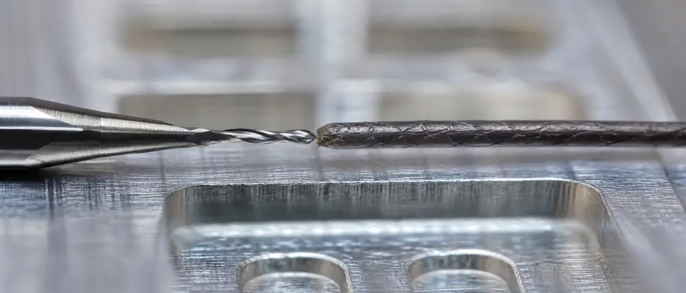
Micro Machining Physics: Transitioning from Shear Mechanics to Elastoplastic Plowing
Conventional CNC machining relies on the assumption that the cutting edge is infinitely sharp relative to the programmed chip load. In macroscopic milling, an uncut chip thickness of 0.1 mm dwarfs an edge hone radius of 0.005 mm. Material shears predictably along the primary shear plane, discharging approximately 80 percent of cutting heat directly into the evacuated chip. Whether producing concentric shafts via ultra-precision CNC turning operations or cutting deep cavities, this macroscopic shear ratio holds true.
In a precision micro milling process, this physical balance reverses. A solid-carbide end mill with an outer diameter of 0.100 mm features an edge radius between 0.001 mm and 0.003 mm due to physical grinding constraints. When CNC feed rates produce an uncut chip thickness smaller than this edge hone, the tool cannot shear the workpiece cleanly. The cutting edge rubs, burnishes, and elastically displaces the metal aside.
The Minimum Chip Thickness Boundary and Elastic Material Recovery
When chip thickness falls below the minimum chip thickness threshold, the cut transitions into plastic plowing. The workpiece material experiences high compressive deformation beneath the tool tip. Once the flute sweeps past, the compressed substrate elastically springs back by 0.0005 mm to 0.0015 mm. This spring-back rubs continuously against the tool relief flank, accelerating abrasive wear. Furthermore, because negligible chip volume forms during rubbing passes, thermal energy cannot exit via chip evacuation. Over 70 percent of frictional heat conducts into the micro cutter and the localized part zone, causing thermal expansion that shifts dimensions mid-cut.
Grain Boundary Heterogeneity and Dynamic Force Fluctuations
In macro machining, engineering alloys function as uniform, isotropic structures. In micro components with 0.050 mm wall thicknesses, the cut path crosses individual crystalline grains measuring 0.010 mm to 0.040 mm across. The cutting edge encounters sudden variations in shear resistance as it crosses from grain interiors into high-angle grain boundaries. This crystallographic variation generates high-frequency harmonic deflection against the cutter shank, turning minor tool vibrations into dimensional variations across the finished part.
Feature Aspect Ratios, Structural Deflection, and the Critical Feed Rate Threshold
Sub-millimeter manufacturability depends strictly on aspect ratio boundaries and tool deflection behavior. When machining micro slots, deep channels, or freestanding structural ribs, tool deflection scales with the third power of tool overhang length and inversely with the fourth power of tool core diameter. Doubling the flute reach of a 0.20 mm cutter reduces its mechanical rigidity by eight times, turning tool deflection into the single largest source of dimensional drift during multi-axis precision CNC milling cycles.
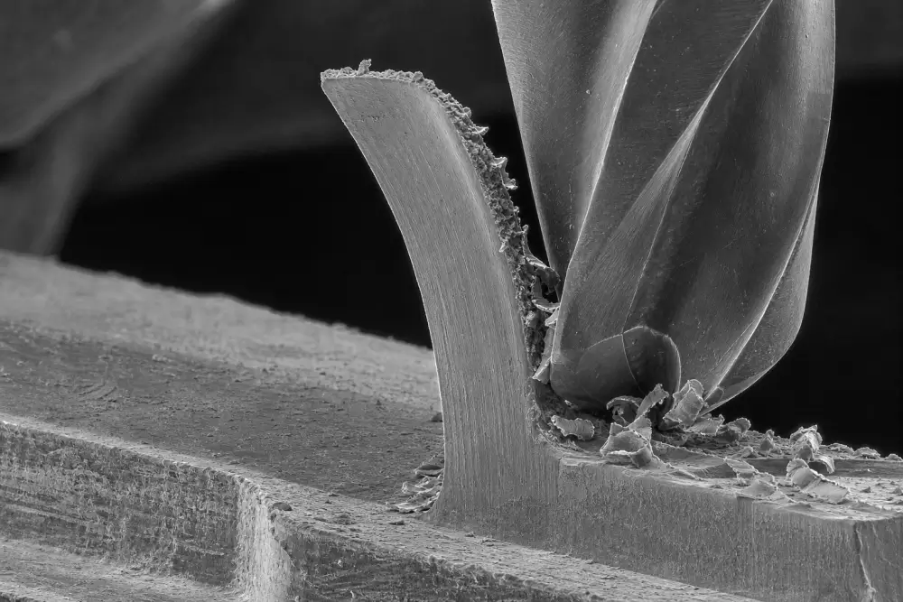
The Feed Rate Paradox: Why Overly Conservative Chip Loads Snap Micro Tools
A frequent error committed by junior programmers and sourcing managers involves reducing the feed per tooth to ultra-conservative values, such as 0.0002 mm per tooth, in an attempt to protect fragile cutters.
Shop-floor testing at Dazao demonstrates that ultra-light feeds accelerate micro tool breakage. When feed per tooth drops below the minimum chip thickness:
· The tool flute slides across the workpiece surface without shearing a clean chip.
· The material surface strain-hardens through mechanical burnishing, increasing local yield strength by up to 45 percent in stainless steels and titanium.
· As the machine axis continues forward interpolation, lateral cutting resistance accumulates until the tool bites into the work-hardened layer.
· The sudden impact exceeds the transverse rupture strength of the sub-micron carbide core, snapping the tool shank instantly.
To preserve tool life and dimensional accuracy, machining paths must maintain a chip load that safely exceeds the minimum chip thickness boundary, established at 15 to 30 percent of the effective cutting edge radius, while managing dynamic deflection forces.
Internal Corner Radii Constraints and Thin-Wall Geometric Boundaries
Micro end mills cannot generate zero-radius internal sharp corners. An engineering drawing calling for a 0.025 mm internal corner radius requires a 0.050 mm diameter cutter. At a slot depth of 0.500 mm, the cutter operates at a 10 to 1 length-to-diameter ratio, where severe deflection destroys dimensional tolerances. Dazao DFM protocols advise design engineers to specify internal corner radii at least 15 percent larger than nominal tool radii to prevent corner dwell chatter.
When designing thin ribs, unsupported sub-millimeter ribs experience harmonic chatter equivalent to macroscopic thin-wall CNC machining dynamics at an amplified frequency. Designers should establish safe micro rib boundaries by cross-referencing parameters in our specialized CNC wall thickness DFM design guide.
|
Feature Type |
Workpiece Material |
Practical Size Limit |
Maximum Aspect Ratio |
Standard Production Tolerance |
|
Micro Rib / Fin |
Al6061-T6 / Al7075 |
0.040 mm thickness |
6 to 1 ratio |
±0.003 mm |
|
Micro Rib / Fin |
Ti-6Al-4V Grade 5 |
0.060 mm thickness |
4 to 1 ratio |
±0.004 mm |
|
Micro Rib / Fin |
Medical PEEK Natural |
0.080 mm thickness |
3 to 1 ratio |
±0.006 mm |
|
Micro Channel |
Al6061-T6 |
0.050 mm width |
5 to 1 ratio |
±0.002 mm |
|
Micro Channel |
316L Stainless Steel |
0.080 mm width |
3 to 1 ratio |
±0.003 mm |
|
Micro Blind Hole |
Oxygen-Free Copper |
0.050 mm diameter |
8 to 1 ratio |
±0.003 mm |
|
Micro Through Hole |
Ti-6Al-4V Grade 5 |
0.100 mm diameter |
12 to 1 ratio |
±0.004 mm |
Spindle Dynamic Stiffness and Total Indicator Runout (TIR) Suppression
In conventional machining, dynamic tool runout of 0.005 mm on a 12.0 mm diameter end mill represents just 0.04 percent of the cutter envelope. In micro end milling, that identical 0.005 mm runout on a 0.100 mm micro cutter represents 5.0 percent of the entire tool diameter and frequently exceeds the total programmed chip load per tooth.
Dynamic Runout Asymmetry: Single-Flute Overloading and Premature Fatigue
Uncontrolled micro milling tool runout transforms a two-flute tool into an unbalanced single-flute cutter. Consider a two-flute 0.200 mm micro cutter operating at 0.0015 mm feed per tooth. If total dynamic indicator runout measures 0.002 mm at the tool tip:
· Flute A takes an excessive chip load of 0.0035 mm, driving stress well beyond its mechanical limit.
· Flute B experiences zero material engagement, sweeping through air without clearing material.
· The resulting asymmetric radial force induces severe cyclical fatigue, degrading surface finish from an intended Ra 0.2 µm to Ra 1.2 µm and snapping the tool within seconds of entry.
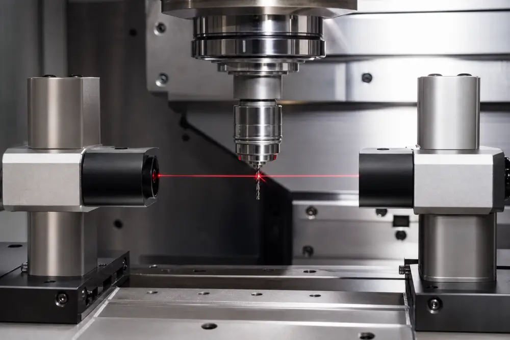
Thermal Shrink-Fit vs. Micro-Hydraulic Holders at 60,000+ RPM
Standard ER collet chucks are mechanically unsuitable for sub-millimeter milling. Even an ER11 collet rated to high-precision standards introduces between 0.003 mm and 0.006 mm of cumulative assembly runout due to thread angle tolerance, collet collapse asymmetry, and clamping nut friction.
Dazao standardizes on two precision tool holding systems for sub-millimeter milling:
1. Precision Thermal Shrink-Fit Holders: By heating the holder bore to seat the carbide shank directly, clamping force remains concentric across 360 degrees. Total runout measured at three times tool overhang consistently holds below 0.0010 mm.
2. Specialized Micro-Hydraulic Holders: Internal hydraulic bladders exert uniform radial pressure along the ground tool shank. These systems dampen high-frequency chatter harmonics during processing of tough aerospace and medical alloys while maintaining dynamic runout within 0.0012 mm.
For spindle platforms, ceramic hybrid ball-bearing spindles provide structural rigidity up to 60,000 RPM, maintaining runout below 0.0015 mm. For mirror surface requirements, aerostatic air-bearing spindles operating up to 120,000 RPM float the shaft on a pressurized air film, reducing total dynamic runout below 0.0003 mm. Suppressing dynamic tool runout at these extreme velocity levels requires rigid machine kinematics found exclusively in specialized multi-axis simultaneous 5-axis CNC machining centers equipped with direct-drive linear motors and active vibration dampening bases.
Non-Contact In-Process Laser Tool Metrology
Mechanical touch probes cannot inspect micro cutters; physical contact with a stylus trigger fractures tools under 0.3 mm diameter instantly. Dazao integrates focused-beam optical laser tool setters directly inside the machine enclosure, using a 0.020 mm optical beam waist to evaluate:
· Dynamic running diameter and tool length at operational RPM.
· True dynamic runout across all cutting flutes.
· Microscopic cutting edge chipping prior to initial workpiece contact.
|
Total Dynamic Indicator Runout Measurement |
Tool Operational Status |
Impact on Cutters Sized 0.200 mm and Below |
|
Under 0.0005 mm |
Optimal Condition |
Balanced dual-flute cutting, maximum fatigue life |
|
0.0006 mm to 0.0015 mm |
Acceptable for Larger Cutters |
30 percent reduction in micro tool fatigue life |
|
Greater than 0.0020 mm |
Critical Failure Threshold |
Instant tool breakage; mandatory holder rejection |
High-Aspect-Ratio Micro Hole Drilling: Hydrodynamic Chip Packing and Tool Wander
Drilling deep micro holes between 0.050 mm and 0.500 mm in diameter exposes cutters to extreme chip packing. In macro drilling, helical flutes lift chips clear of the cutting zone via continuous shear. In micro hole machining, the cross-sectional flute area of a 0.100 mm solid-carbide drill is so restricted that chip accumulation triggers instant torque spikes, snapping the drill within milliseconds.
Deep micro-drilling cycles require modifying standard geometry rules outlined in our comprehensive CNC hole design guide to account for surface tension and rapid chip accumulation.
Progressive Peck Drilling Kinematics and Retraction Deceleration
Standard canned cycles fail when drilling sub-millimeter holes with depth-to-diameter ratios exceeding 5 to 1. Successful chip evacuation requires progressive peck cycles:
· Initial Guide Peck: The first peck stroke reaches 1.0 to 1.5 times the drill diameter, establishing a rigid cylindrical guide inside the hole.
· Progressive Peck Decay: Subsequent pecks decrease to 0.2 or 0.1 times the drill diameter as depth increases, compensating for accumulated wall friction.
· Complete Flute Clearance: The micro drill retracts fully out of the hole on every stroke, allowing directed micro-filtered fluid to clear packed chips from the flutes.
· Controlled Re-entry Deceleration: Rapid traversing back to the previous cut depth causes hydraulic shock when cutting fluid is trapped in the bottom of the blind hole. The drill must decelerate 0.05 mm above the previous cut floor to prevent hydraulic pressure from snapping the drill tip.
Flat-Bottom Micro Pilot Pocketing for Positional Drift Control
A micro drill cannot self-center on an un-machined, raw surface. Even a 0.002 mm lateral deflection across the surface skin causes the drill to skate, wandering off true position and failing positional tolerance specifications. Dazao standard operating procedures mandate machining an ultra-flat pilot pocket using a flat-bottom micro end mill prior to drill entry. This pilot pocket features a diameter 0.005 mm larger than the drill and a depth equal to half the drill diameter. The micro drill enters this flat seat perpendicularly, keeping hole location tolerances within ±0.002 mm true position across production runs.
Micro-Burr Formation Mechanisms and Damage-Free Component Cleaning
Burr formation in micro processing cannot be corrected with manual edge-breaking tools, abrasive belts, or rotary brushes. A deburring tool in human hands exerts forces measured in tens of Newtons, which will flatten or shear sub-millimeter walls, destroy knife edges, and ruin part geometry. Effective micro machining burr control must be engineered directly into the machining cycle and chemical post-processing.
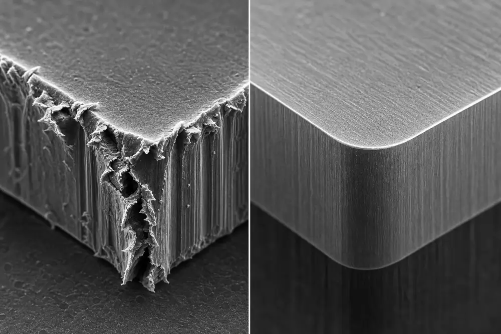
Kinematic Burr Suppression: Roll-Around Climb Milling Paths
Micro burrs form primarily as Poisson burrs and rollover exit burrs. Poisson burrs develop along the lateral sides of a channel as the tool compresses material laterally, forcing plastically deformed metal over the edge. Rollover burrs occur when the micro cutter breaks out of an edge: as the remaining unsupported wall thins below the chip thickness, material bends away from the cutter path rather than shearing cleanly.
To suppress exit burrs, Dazao CAM programming employs climb milling exclusively, combined with roll-around tool paths that exit surfaces along an arc. This toolpath maintains continuous compressive support on the workpiece boundary, reducing burr heights from 0.030 mm down to less than 0.002 mm. For mission-critical sub-millimeter features where absolute zero-burr conditions are strictly required, removing residual Poisson micro-burrs without eroding base edges requires specialized precision surface finishing solutions such as controlled electropolishing and targeted chemical smoothing.
The Ultrasonic Cleaning Hazard: Megasonic Cavitation and Capillary Entrapment
Cleaning micro components presents severe, undocumented manufacturing risks. When micro-machined parts with walls thinner than 0.080 mm enter industrial ultrasonic cleaning tanks, standard 28 kHz or 40 kHz ultrasonic cavitation generates localized micro-jets with shock pressures exceeding 50 MPa. These localized pressure pulses bend, fatigue, and shear delicate micro ribs off the substrate.
Furthermore, liquid surface tension acts as a physical barrier in micro features. In blind holes smaller than 0.200 mm diameter, the surface tension of standard cleaning water or aqueous solvents prevents fluids from penetrating the cavity. Trapped cutting fluids and microscopic chips remain sealed inside the hole by capillary action. Over time, trapped coolant causes galvanic micro-corrosion, prevents chemical passivating agents from coating the cavity, and blinds optical metrology systems during final inspection.
Dazao resolves this through a structured post-processing protocol:
· Solvent Surface-Tension Modification: Formulated cleaning solutions use specialized fluorinated solvents with ultra-low surface tension under 18 mN/m combined with vacuum degassing chambers to displace trapped gas pockets inside micro blind cavities.
· Low-Frequency Megasonic Cleaning: The cleaning process replaces standard ultrasonic cavitation with gentle 400 kHz to 1 MHz megasonic agitation. This frequency range strips sub-micron particulate without generating destructive micro-jet shockwaves against thin metal walls.
· Vacuum Evaporation Drying: Finished components dry inside a vacuum furnace where sub-atmospheric pressure flashes out residual moisture from micro channels without air-nozzle blast distortion.
Alloy Microstructure Behavior: From Ductile Adhesion to Thermal Degradation
Material machinability ratings developed for macro CNC operations do not translate to micro scales. Material microstructures, inclusion sizes, and grain orientations dictate tool wear, chip formation, and finished part yields.
|
Material Specification |
Micro Machinability Index |
Primary Failure Mode |
Tooling and Coating Selection |
Target Cutting Speed |
|
Al6061-T6 / Al7075-T651 |
High |
Chip re-welding, rapid Built-Up Edge |
Diamond-Like Carbon or uncoated carbide |
40 to 80 m/min |
|
Ti-6Al-4V ELI (Grade 23) |
Moderate |
Severe work hardening, concentrated edge heat |
AlTiN or TiSiN nanocomposite coating |
15 to 30 m/min |
|
316L Stainless Steel |
Poor |
High ductility, extreme rollover burr formation |
Multi-layer AlCrN nano-coatings |
12 to 25 m/min |
|
Medical PEEK (Optima) |
Moderate |
Thermal softening, microscopic burr fuzzing |
Polished single-crystal diamond or razor carbide |
50 to 100 m/min |
|
Oxygen-Free Copper (C10100) |
Difficult |
High plasticity, severe side-wall smearing |
High-rake uncoated carbide with mirror flutes |
30 to 60 m/min |
Aluminum Alloy Micro-Milling: Chip Adhesion and DLC Coating Performance
When performing micro machining aluminum, the primary mode of failure is built-up edge. Ductile aluminum sticks to the cutting edge under cutting pressure. When machining with a 0.2 mm tool, a built-up edge of just 0.005 mm alters the cutting geometry entirely, eliminates rake clearance, and fractures the tool shank.
Chip morphology during high-speed spindle operations aligns with the behavioral parameters analyzed in our comprehensive aluminum CNC machining technical guide. Dazao applies ultra-smooth Diamond-Like Carbon coatings with friction coefficients below 0.1 to prevent chip adhesion.
Surgical-Grade Titanium (Ti-6Al-4V) and Implantable PEEK Machinability
When executing micro CNC machining for medical devices, titanium alloys and bio-inert polymers require tight thermal management:
· Titanium Grade 5 (Ti-6Al-4V): The low thermal conductivity of titanium channels cutting heat directly into the microscopic tool tip. High-pressure micro-mist coolant must deliver continuous lubrication at the tool-workpiece interface to prevent cutting edge thermal degradation.
· Medical PEEK: High-speed processing easily exceeds the 143°C glass transition temperature of PEEK, softening local features and causing the polymer to gum up around tool flutes. Machining strategies require high feeds, razor-sharp uncoated cutting edges, and chilled air cooling to produce brittle chip separation and eliminate edge fuzzing.
Non-Destructive Micro-Workholding: Clamping Distortion Mitigation
Standard mechanical vices and chucks apply uncontrolled clamping forces that plastically crush, bow, or distort micro parts. Clamping a 2.0 mm by 2.0 mm housing with 0.1 mm wall thicknesses inside a conventional vice introduces clamping strains that consume the entire component tolerance budget before the spindle even turns on.
|
Part Geometry Classification |
Standard Machine Clamping Risk |
Dazao Precision Micro-Fixturing Solution |
|
Thin Foils and Planar Arrays |
Mechanical toe clamps cause localized bowing |
Porous ceramic vacuum chucks with optical flatness |
|
Fragile 3D Micro Housings |
Vices crush thin-walled perimeter features |
Phase-change water-soluble adhesive wax beds |
|
Multi-Axis Complex Implants |
Manual flipping loses sub-micron datums |
Integrated sacrificial runner frames with tab separation |
Porous Ceramic Vacuum Chucks and Phase-Change Adhesive Mounting
For planar substrates, micro-fluidic chips, and thin sheet arrays, porous ceramic vacuum chucks pull parts down onto an optically flat bed. Clamping force distributes evenly across the entire surface area without localized stress points.
For miniature 3D housings that lack parallel clamping faces, parts bond to sacrificial tooling plates using water-soluble glycol waxes or UV-curable polymer matrices. Once machining finishes, elevating the bath temperature to 65°C or washing in warm water releases the part without mechanical stress.
Integrated Sacrificial Runner Frames for Multi-Axis Processing
Complex multi-sided components remain anchored inside their raw stock via engineered 0.05 mm tabs. All milling, drilling, and finishing cycles complete on 5-axis platforms in a single setup. A final precision wire EDM pass, laser micro-cut, or controlled mechanical tab separation detaches the finished component from the carrier frame without manual handling damage.
Technology Trade-Off: Micro CNC Milling vs. Micro Electrical Discharge Machining
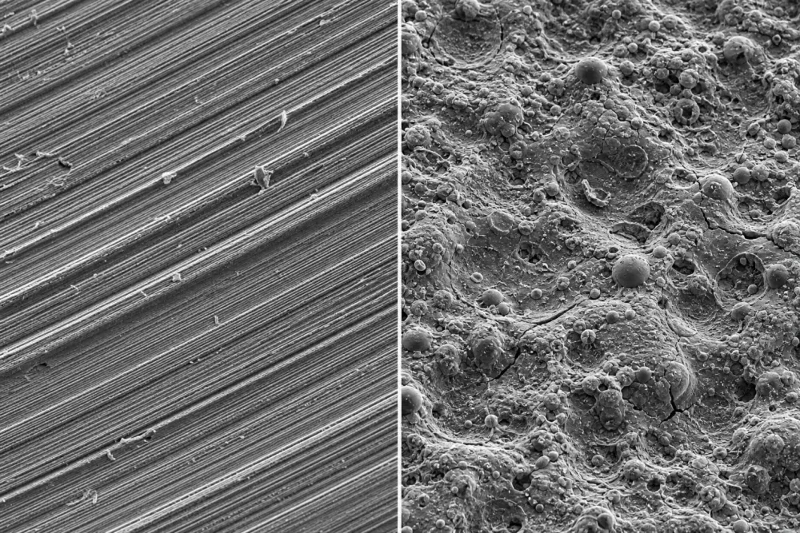
Sourcing teams regularly evaluate micro machining vs micro EDM when selecting manufacturing paths for sub-millimeter features. While micro CNC utilizes mechanical shear to remove metal, micro EDM uses controlled high-frequency electrical spark erosion.
|
Technical Parameter |
Micro CNC Machining |
Micro EDM (Sink and Wire) |
|
Material Compatibility |
All metals, engineering plastics, composites |
Conductive metals and semimetals only |
|
Minimum Internal Corner Radius |
Limited by tool radius down to 0.015 mm |
Limited by wire radius and spark gap down to 0.005 mm |
|
Maximum Aspect Ratio |
5 to 1 up to 10 to 1 depending on geometry |
Exceeds 20 to 1 for holes and deep slots |
|
Subsurface Metallurgical Integrity |
Base material lattice preserved, zero heat-affected zone |
Thermally altered recast layer 0.001 mm to 0.005 mm thick |
|
Surface Roughness (Ra) |
Ra 0.1 to 0.4 µm directly achieved |
Ra 0.2 to 0.8 µm with characteristic spark cratering |
|
Volumetric Removal Rate |
High in low-to-medium aspect ratio geometries |
Inherently slow volumetric material removal rate |
|
Tool Wear Impact on Cost |
High cutter breakage risk during unattended runs |
Continuous wire consumption or electrode redressing costs |
Subsurface Metallurgical Integrity: Sheared Lattices vs. Recast Heat Layers
Micro CNC milling preserves the original crystalline grain structure of the alloy, delivering smooth compressive stress profiles essential for dynamically loaded components like medical bone screws and aerospace fuel injectors. Micro EDM leaves a recast layer containing microscopic thermal tension cracks that reduce component fatigue life. Choose micro CNC milling when your component requires high structural fatigue life, utilizes non-conductive polymers like PEEK, or features continuous 3D contoured profiles. When aspect ratios exceed 15 to 1 or internal corner radiuses drop below 0.010 mm, transitioning to our high-precision wire EDM services provides superior dimensional control.
Choose micro CNC milling when your component requires high structural fatigue life, utilizes non-conductive polymers like PEEK, or features continuous 3D contoured profiles. When aspect ratios exceed 15 to 1 or internal corner radiuses drop below 0.010 mm, transitioning to specialized wire electrical discharge machining provides superior dimensional control.
Sub-Micron Inspection Blind Spots: Optical Artifacts and Thermal Drift
A micro feature cannot be declared conforming if the measurement system introduces more uncertainty than the drawing tolerance allows. Standard touch-trigger Coordinate Measuring Machines cannot inspect micro features: a 0.5 mm ruby probe tip cannot enter a 0.1 mm micro slot, and probe contact forces of 0.05 N will elastically deflect a 0.06 mm thin rib, resulting in false out-of-tolerance readings.
When establishing quality control criteria, refer to our aluminum CNC machining tolerances engineering guide to distinguish macroscopic limits from micro-scale thermal drift.
Optical Shadow Pseudo-Features and Sub-Pixel Boundary Calculation
Engineers often rely on high-magnification optical profile projectors, vision systems, or laser confocal microscopes. However, optical systems introduce subtle measurement errors:
· Shadow Pseudo-Features: In high-aspect-ratio channels, vertical walls cast optical shadows under ring illumination. The vision system edge-detection algorithm may mistake the shadow transition for the true physical wall boundary, reporting false slot-width errors up to 0.008 mm.
· Sub-Pixel Contrast Shifts: When inspecting rounded micro edges, subtle lighting changes alter pixel brightness thresholds. A minute edge burr of 0.0015 mm can cause the edge algorithm to flag an entire feature diameter as non-conforming.
· Focus Depth Ambiguity: In lenses with high numerical apertures, the shallow depth of field requires multi-plane focus stacking. If focal planes shift during measurement, vertical Z-axis dimensions can register false step errors.
The Human Thermal Interface: Fixture Expansion and Climate Stabilization
The volumetric thermal expansion coefficient of Al6061-T6 is approximately 23 micro-strains per degree Celsius. Consider an aluminum micro fixture holding parts to an inspection tolerance of ±0.002 mm across a 50.0 mm span:
· An ambient temperature shift of just 2.0°C in the inspection room expands the fixturing setup by 0.0023 mm.
· If an operator picks up the micro part or its holding fixture with bare hands, skin contact transfers body heat, driving the local metal temperature from 20°C to 26°C within 30 seconds.
· This localized 6°C rise generates over 0.0069 mm of thermal expansion, completely overwhelming the allowable ±0.002 mm tolerance band.
Dazao controls these variables through dedicated Class 10,000 clean inspection facilities. Components, custom fixturing, and optical measurement devices undergo a mandatory 4-hour thermal equilibrium soak at 20.0°C ± 0.2°C prior to final inspection. Parts are manipulated exclusively using thermally insulated tweezers, and optical boundary calculations apply sub-pixel edge detection algorithms to eliminate shadow false rejections.
Micro CNC Cost Structure Drivers and Manufacturing-Ready RFQ Best Practices
Understanding the primary drivers of micro CNC machining cost allows procurement professionals and engineering teams to adjust drawing requirements and eliminate unnecessary manufacturing expenses. To control prototype expenses, sourcing teams should consult our engineering breakdown of aluminum CNC machining cost drivers when establishing production tolerances.
|
Cost Generation Category |
Share of Total Part Cost |
Primary Expense Driver on Shop Floor |
Sourcing Optimization Opportunity |
|
CAM Setup and Alignment |
35 percent |
5-axis kinematic calibration, laser tool setting |
Bundle prototype volumes to amortize setup costs |
|
Tooling Consumption |
25 percent |
Micro-diameter carbide wear, breakage during setup |
Standardize corner radii to standard tool diameters |
|
Optical Metrology and QA |
25 percent |
Multi-plane confocal scanning, thermal stabilization |
Apply sub-micron tolerances only to critical datums |
|
Machine In-Cut Time |
15 percent |
Multi-peck drilling, low feed finish passes |
Relax non-functional cavity depths and surface callouts |
Review your engineering drawings against our practical CNC DFM checklist for manufacturing-ready parts before finalizing tight clearance notes. Before submitting a Request for Quotation for sub-millimeter components, evaluate your drawing against these criteria:
· Allow Internal Corner Relief: Replace sharp inside corners with radius callouts at least 15 percent larger than standard tool sizes, such as specifying R 0.120 mm instead of R 0.100 mm.
· Avoid Flat-Bottom Deep Hole Callouts: Flat-bottom micro holes require an extra finishing pass with a fragile flat end mill. Allow standard drill point angles between 118 degrees and 140 degrees whenever permissible.
· Isolate High-Tolerance Zones: Apply ±0.002 mm tolerances only to mission-critical alignment fits. Relax non-functional clearance channels and pocket depths to ±0.025 mm to cut inspection and cycle times in half.
· Define Burr Magnification Thresholds: Rather than calling for unquantified zero-burr conditions, specify burr limits under defined magnification, such as requiring no burrs detectable under 30x optical magnification.
Shop-Floor Case Evidence: Medical Hinges, Optical Arrays, and Failure Post-Mortem
Medical Articulation Linkage: Titanium Grade 5 ELI
· Part Geometry: Miniature multi-axis hinge link measuring 1.80 mm by 1.20 mm by 0.80 mm, featuring 0.25 mm pivot pin bores and 0.08 mm thin side walls.
· Manufacturing Strategy: Dazao engineered a dual-station fixture holding parts on sacrificial runners. We used a 0.20 mm CVD diamond-coated end mill for pocketing and a 0.245 mm micro drill followed by an ultra-fine reaming pass. Micro-mist cutting fluid prevented chip adhesion, and parts completed burr-free using high-resolution roll-around tool paths.
· Production Result: 100 percent conformance across a 5,000-piece production batch with process capability index values holding above 1.45 on critical pin bore centers.
Optoelectronic Alignment Block: Silicon-Photonic Fiber Guide Array
· Part Geometry: Multi-channel optical array block requiring eight parallel V-grooves spaced at 0.127 mm pitch, groove depths of 0.090 mm, and surface finish targets of Ra 0.1 µm.
· Manufacturing Strategy: Machined on a 5-axis platform equipped with an aerostatic air-bearing spindle operating at 90,000 RPM. We used custom single-crystal diamond 60-degree V-point cutters. The workpiece was secured using a porous ceramic vacuum plate, and the machine enclosure maintained a temperature of 20°C ± 0.1°C throughout the continuous cycle.
· Production Result: Pitch error measured less than 0.0008 mm across all eight channels, with channel wall roughness verified at Ra 0.08 µm, eliminating optical light scatter along the fiber alignment path.
Production Post-Mortem: Unvented Micro Blind Hole Tool Burst
· The Failure: During early prototype fabrication of an aerospace sensor housing, 0.150 mm carbide drills snapped consistently upon reaching 1.20 mm depth in 316L stainless steel, resulting in high scrap rates.
· Root Cause Investigation: The engineering drawing specified a 0.150 mm blind hole with an 8 to 1 aspect ratio and zero relief taper. High-pressure coolant entered the micro hole during deep peck cycles. As the drill descended back to cut depth, the trapped fluid could not escape past the narrow flute margins. The resulting hydraulic backpressure generated an axial load that buckled the drill shank before the cutting edge ever touched the bottom floor.
· DFM Resolution: Dazao consulted with the customer engineering team to incorporate a 1-degree draft angle along the non-functional hole depth and implemented a CAM clearance dwell cycle that purged fluid before rapid re-entry. Drill life immediately stabilized from 1 hole per tool to over 45 holes per tool, cutting prototype production costs by 68 percent.

Frequently Asked Questions (FAQ)
01.Why do micro end mills snap instantaneously during extremely light finishing passes?
02.How can ultrasonic cleaning damage sub-millimeter machined components?
03.What causes micro drills to snap during retraction in deep blind holes?
04.Why do optical vision inspection systems generate false rejects on micro features?
05.How does inspector body temperature affect micro tolerance verification?
06.How do you remove microscopic burrs without destroying sub-millimeter part geometry?





