


Cutting fluid is an active functional cutting tool component, not an auxiliary cleaning solvent. Selecting between soluble oils, semi-synthetics, and synthetics directly governs tool deflection, cycle times, and scrap rates. In Al6061-T6 and Al7075 milling, uncontrolled fluid chemistry causes built-up edge (BUE), severe thread galling, and galvanic oxidation. Maintaining target concentration via refractometer monitoring and removing tramp oil preserves ±0.005 mm tolerances and eliminates unplanned spindle downtime.
Coolant Dynamics: Engineering the Cutting Fluid as an Active Tool Geometry Component
In standard contract manufacturing, management frequently categorizes cutting fluid alongside floor degreasers and absorbent pads: a generic operational consumable purchased solely on bulk unit cost. Treating metalworking fluid as a secondary wash medium rather than an active component of the cutting tool assembly introduces systemic process instability. The fluid interface at the shear plane controls chip formation mechanics, thermal expansion of the workpiece, frictional rubbing along the tool flank, and high-speed evacuation of abrasive particulates across our precision CNC machining services across multi-axis cells.
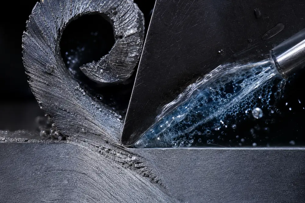
This technical CNC machining coolant guide provides production data derived from two decades of precision component manufacturing at Xiamen Dazao Machinery. Operating multi-axis machining cells under ISO9001:2015 and IATF16949:2016 certifications demonstrates that fluid mismanagement directly drives common shop-floor disasters:
The Monday Morning Odor Phenomenon: Fluid sumps left uncirculated over a 48-hour weekend shift undergo rapid dissolved oxygen depletion. Anaerobic bacteria (notably Desulfovibrio) metabolize sulfur compounds, releasing hydrogen sulfide gas, dropping sump pH below 7.5, and destabilizing the emulsion chemistry.
Micro-Tear Thread Failures: In blind-hole rigid tapping of 6061-T6 aluminum, degraded fluid lubricity increases cutting torque spikes by over 40%. The result is stripped pitch diameters, micro-welding on the tap flanks, and scrapped aerospace housings.
Delayed Galvanic Surface Staining: Workpieces machined with unbalanced, acidic coolant show flawless dimensions at final inspection, yet develop irreversible white-pitting oxidation inside vacuum-sealed packaging during transoceanic shipping.
For procurement directors and project managers, cutting fluid accounts for less than 1.5% of total production expenses. However, unmonitored fluid contributes to more than 15% of unexpected machining scrap, unpredicted tool wear, and secondary surface finishing rejections. Workpiece accuracy relies on mechanical axis calibration alongside holding rigid dimensional repeatability and tight CNC tolerances. Managing machine tool health requires equal technical focus on mechanical axes and the fluid sump below them.
Chemical Architecture: Technical Breakdown of the Four Primary Metalworking Fluids
Metalworking fluids fall into four distinct categories defined by oil content, emulsifier systems, and synthetic lubrication packages. Each variation exhibits specific boundaries for heat absorption, lubricity, fluid life, and biological resistance. Selecting the appropriate CNC coolant types requires balancing the mechanical heat-to-friction ratio of the designated cutting process.

Water-Soluble Emulsions (Soluble Oils)
Soluble oils consist of 60% to 85% severely refined mineral oil blended with petroleum sulfonates, emulsifiers, and coupling agents. When mixed with water, they produce an opaque, milky-white emulsion with droplet diameters ranging between 1 and 5 microns.
· Tribological Mechanism: The high concentration of free oil droplets delivers an uninterrupted hydrodynamic film along the tool flank face, preventing metal-to-metal contact during low-speed, high-load operations.
· Technical Limitations: High mineral oil volume provides a direct nutrient base for bacterial proliferation. When water hardness climbs past 350 ppm, calcium and magnesium ions break the surfactant bonds, causing oil separation and gummy residues across linear guide rails.
· Optimal Operations: Heavy broaching, general turning of medium-carbon steels (AISI 1045), and high-load tapping below 40 m/min surface speeds.
Semi-Synthetic Fluids
Semi-synthetics integrate 5% to 30% mineral oil combined with synthetic esters, biostable amines, and micro-emulsifiers. The resultant fluid exhibits a translucent to micro-opaque visual profile, with droplet diameters under 0.1 microns, making it ideal for production environments utilizing high-precision CNC milling platforms.
· Tribological Mechanism: The smaller micelle dimensions increase the fluid's total surface wetting area. This architecture balances high thermal dissipation capacity with dependable boundary-layer lubrication.
· Technical Limitations: Tramp oil integration easily destabilizes semi-synthetic emulsions if skimmers are neglected. Certain formulations generate micro-foaming when pressurized past 20 Bar in low-hardness water.
· Optimal Operations: Multi-axis CNC milling centers running diverse batches of carbon steels, 300-series stainless steels, and copper alloys under variable feed rates.
Fully Synthetic Coolants
Synthetics eliminate petroleum base oils entirely. Formulations rely on water-soluble polyalkylene glycols (PAG), surface-active wetting agents, organic corrosion inhibitors, and biostable conditioning chemicals. The fluid remains completely clear during operation.
· Tribological Mechanism: Heat removal mirrors the specific heat capacity of water (4.184 J/g°C), maximizing cooling directly at the primary shear plane. High-speed surface flushes sweep away chips before heat can migrate into the machine spindle or part fixture.
· Technical Limitations: Synthetic formulations lack natural boundary lubrication films under severe friction loads, increasing built-up edge risks during heavy aluminum cuts. Residual salts can strip protective paint coatings on older CNC enclosures and wash out way lube oils.
· Optimal Operations: Carbide surface grinding, fine boring, cast iron processing, and ultra-high-speed profiling where thermal expansion stability supersedes extreme-pressure lubricity.
Neat Straight Oils
Straight oils are pure petroleum or ester-based formulations run without water dilution. Additive packages integrate extreme pressure (EP) chlorine, active sulfur, and phosphorus compounds to maintain lubricating films past 800°C.
· Tribological Mechanism: Pure boundary lubrication. The fluid prevents friction-induced chip welding, eliminating chip-welding marks on fine finish passes.
· Technical Limitations: Heat extraction capacity is low (specific heat around 1.67 to 2.0 J/g°C). High cutting speeds generate heavy oil mists and airborne volatile organic compounds (VOCs), introducing flash fire hazards if run without automated mist suppression systems.
· Optimal Operations: Deep-hole gun drilling (L/D ratios greater than 15:1), precision gear hobbing, and high-volume Swiss screw machining of medical implants.
Engineering Comparison: Coolant Chemistries Under Operational Load
|
Performance Parameter |
Soluble Oil (Emulsion) |
Semi-Synthetic Fluid |
Synthetic Coolant |
Neat Straight Oil |
|
Mineral Oil Content (%) |
60% – 85% |
5% – 30% |
0% |
100% |
|
Viscosity (cSt @ 40°C, neat) |
25 – 45 |
30 – 60 |
15 – 35 |
10 – 40 |
|
Heat Dissipation Rating |
Moderate |
High |
Maximum |
Low |
|
Boundary Lubricity (EP) |
High |
Moderate to High |
Low to Moderate |
Maximum |
|
Bacterial Resistance |
Poor (Requires Biocides) |
Moderate to High |
High (Inorganic) |
Immune (Zero Water) |
|
Sump Longevity (Months) |
3 – 6 |
6 – 12 |
12 – 24 |
24 – 48 |
|
Post-Wash Complexity |
Solvent / Alkaline Wash |
Mild Alkaline Wash |
Aqueous Rinse |
Hydrocarbon Degreaser |
Metallurgy and Fluid Chemistry: Formulating for Aluminum and Extreme-Temperature Alloys
Matching cutting fluid formulation to workpiece metallurgy determines whether a production run maintains dimensional tolerance or scraps components through thermal distortion and chip welding, following best practices established for aluminum CNC machining.
Boundary Lubrication Dynamics in Aluminum Alloys
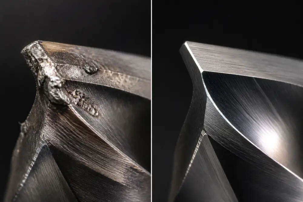
Aluminum alloys like Al6061-T6, Al7075-T651, and cast A380 possess exceptional thermal conductivity, but their low melting point and chemical affinity for tungsten carbide introduce severe chip welding hazards. At shear temperatures above 300°C, chip material adheres mechanically to the rake face, forming a dynamic built-up edge (BUE). As this built-up material breaks away during cutting, it tears carbide grains from the tool substrate, degrading the surface finish from Ra 0.8 to over Ra 3.2 in minutes and causing unplanned surges detailed in our aluminum CNC machining cost breakdown.
Deploying optimized CNC coolant for aluminum machining demands precise additive selection:
· Chlorine and Active Sulfur Exclusions: Chlorinated additives trigger stress corrosion cracking and micro-staining on non-ferrous surfaces. Active sulfur chemically stains structural alloys, creating dark copper-sulfide layers that prevent uniform post-machining chemical treatments.
· Synthetic Esters and Polymeric Friction Modifiers: High-performance formulations for coolant aluminum applications use non-ionic surfactants paired with synthetic polar esters. These polar molecules bond securely to the positive ionic charges on freshly cut aluminum, generating an anti-weld barrier under extreme feed pressures.
· Non-Silicone Defoaming Agents: Residual silicone defoamers adhere tenaciously to finished parts. When parts pass to downstream Type II/III anodizing or structural bonding, trapped silicone causes uneven dye absorption and coating delamination.
Chemistry Configurations for Stainless Steels, Titanium, and Gray Iron
Austenitic Stainless Steels (AISI 304 / 316L): Low thermal conductivity and rapid work-hardening demand high concentrations (10% to 12%) of semi-synthetic fluids loaded with passive, deactivated sulfurized esters. The chemistry must lubricate the cutting edge instantly before chip deformation triggers strain hardening.
Titanium Alloys (Ti-6Al-4V): Titanium generates localized shear temperatures past 900°C due to virtually zero thermal conductivity into the chip. The coolant must provide rapid heat removal while withstanding high mechanical shear. Fluid breakdown leads directly to rapid micro-cracking and catastrophic tool tip failure.
Gray and Ductile Cast Iron: Free graphite particles within iron act as solid internal lubricants but quickly contaminate standard water-soluble sumps. Cast iron dust converts mineral oils into thick, abrasive slurries. Formulations require fully synthetic fluids with rapid fines-settling additives and elevated anti-rust inhibitors to prevent flash corrosion on machine ways.
Material vs. Coolant Chemistry Selection & Risk Matrix
|
Workpiece Material |
Recommended Fluid Chemistry |
Target Concentration |
Critical Chemical Additives |
Principal Failure Risk |
|
Al6061-T6 / Al7075 |
Semi-Synthetic (High Ester) |
8% – 10% |
Polar Polymeric Esters, Non-Silicone Defoamer |
Built-Up Edge, Tap Galling, Post-Anodize Staining |
|
AISI 304 / 316L |
Soluble Oil or Semi-Synthetic |
10% – 12% |
Inactive Sulfurized Fatty Oils, Phosphorus EP |
Work-Hardening, Flank Wear, Micro-Chipping |
|
Ti-6Al-4V Grade 5 |
Semi-Synthetic / Synthetic |
10% – 14% |
High-Lubricity Synthetic Esters, Wetting Agents |
Thermal Tool Cracking, Workpiece Shrinkage |
|
Gray Cast Iron (HT250) |
Fully Synthetic |
5% – 7% |
Inorganic Corrosion Inhibitors, Fines Coagulants |
Flash Rusting, Sump Sludge Loading, Skin Dermatitis |
Hydraulic Delivery Regimes: Comparing Flood Cooling, High-Pressure Systems, TSC, and MQL
Selecting the optimal delivery mechanism requires matching the fluid's thermal-mechanical limits to the physical tool path. If cutting fluid fails to penetrate the vapor barrier at the tool-workpiece interface, even advanced chemical formulations fail.
Low-Pressure Flood Delivery Limitations
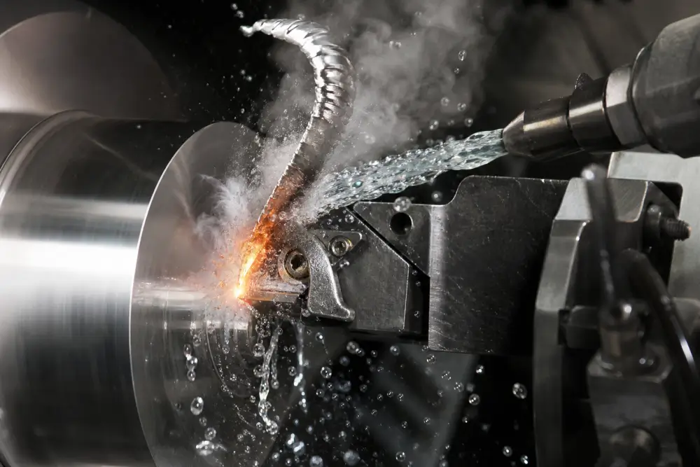
Traditional flood delivery pumps cutting fluid through flexible external loc-line nozzles at pressures between 2 and 5 Bar.
· The Hydrodynamic Deflection Problem: At spindle speeds exceeding 8,000 RPM, the rotating tool acts as a centrifugal fan, generating an air boundary layer that deflects low-pressure fluid streams away from the cut.
· Cavitation and Thermal Shock: In deep cavity milling, external nozzles direct fluid onto the tool shank rather than the cutting edge, multiplying cavitation risks inherent to deep pocket CNC machining. In intermittent milling passes, the cutting insert cycles between extreme dry friction heat (700°C) and sudden re-immersion in cold flood fluid. This rapid thermal cycling induces micro-cracking across the carbide substrate, leading to premature edge chipping.
High-Pressure Delivery and Through-Spindle Engineering
When evaluating flood coolant vs through spindle coolant, the critical physical differentiator is kinetic energy at the shear zone. Modern CNC platforms deploy high pressure coolant machining systems operating between 20 Bar and 70 Bar, channeling fluid through internal passages in the tool holder and cutting tool.
· Vapor Barrier Penetration: High cutting zone temperatures vaporize incoming water, establishing an insulating steam envelope around the tool tip. Coolant delivered at 70 Bar overcomes this vapor barrier, providing liquid contact directly at the tool flank and rake faces.
· Mechanical Chip Breaking: In high-feed turning of austenitic stainless steels and aerospace superalloys, high-pressure fluid jets act as mechanical wedges. The directed force bends stringy swarf upwards against the tool's molded chip breaker, snapping chips into small 6-shaped segments and preventing chip entanglement around the spindle.
· Operating Limitations: High-pressure delivery introduces mechanical side-loads. Tools exceeding an overhang ratio of 5:1 can experience micro-deflection when hit with asymmetrical high-pressure jets, inducing dimensional taper along deep walls. Through-spindle delivery requires sub-10-micron filtration units; particulates larger than 15 microns will clog internal coolant orifices, triggering thermal tool destruction within seconds.
Minimum Quantity Lubrication (MQL) Mechanics
When analyzing MQL vs flood coolant CNC machining, manufacturing engineers balance thermal cooling against pure boundary lubrication. MQL atomizes micro-droplets of pure ester or vegetable-based oil into an active compressed air stream at consumption rates between 10 and 50 ml per operating hour.
· Operational Advantages: MQL eliminates post-machining chemical washes, leaves dry chips with high scrap resale value, and eliminates bacterial fluid maintenance costs entirely.
· Physical Processing Limits: MQL provides virtually zero bulk heat removal. In aggressive roughing passes, workpiece thermal expansion must be compensated dynamically via software algorithms, diverging from strategies optimized for high-speed machining aluminum components.
· The Chip Evacuation Failure Mode: When pocket depths exceed three times the tool diameter (3xD), compressed air lacks the mass flow density required to hoist chips out of deep cavities. Un-evacuated chips drop to the bottom of the slot, leading to chip re-cutting, severe work-hardening, and catastrophic end mill breakage.
Delivery Methods: Engineering Comparison
|
Delivery Strategy |
Delivery Pressure (Bar) |
Primary Mechanism |
Chip Evacuation Capability |
Thermal Shock Risk |
Tool Life Impact (Stainless/Inconel) |
|
External Flood Coolant |
2 – 5 |
Bulk Heat Removal |
Moderate (Shallow Pockets Only) |
High (Thermal Cycling) |
Baseline (1.0x) |
|
Through-Spindle Coolant (TSC) |
20 – 40 |
Direct Zone Flushing |
High (Deep Holes & Blind Cavities) |
Low (Constant Immersion) |
1.8x – 2.5x |
|
High-Pressure Jet (HPC) |
50 – 80 |
Vapor Barrier Penetration |
Maximum (Dynamic Chip Fracture) |
Very Low |
2.5x – 4.0x |
|
Minimum Quantity Lubrication (MQL) |
4 – 8 (Pneumatic) |
Boundary Friction Reduction |
Poor in Deep Features (>3xD) |
N/A (Dry Environment) |
0.8x – 1.3x |
|
Cold Air Blast (-20°C) |
5 – 7 |
Chip Evacuation & Quenching |
Moderate |
Moderate |
0.5x – 0.9x |
Micro-Contamination Realities: Three Unpublicized Shop-Floor Failure Modes
Mainstream machining literature details basic fluid degradation metrics like foul odors and rust. However, high-precision machining environments encounter more subtle failure mechanisms that escape standard inspection routines.
Failure Mode 1: Refractometer Masking by Tramp Oil Emulsification
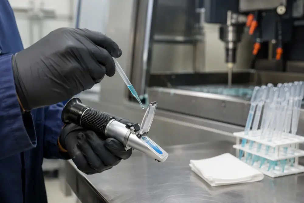
Operators frequently measure water-soluble coolant using an analog CNC coolant refractometer, observing a clean line at an apparently correct 8% Brix reading. Hours later, carbide end mills fail prematurely, exhibiting severe flank friction wear.
· The Underlying Mechanism: Tramp oil from machine slideways (ISO VG 68 way lube) drips continuously into the fluid sump. Under high-shear agitation from the main delivery pump, the chemical emulsifiers in the cutting fluid slowly pull these insoluble hydraulic and slideway oils into a micro-suspension.
· The Refractometer Blind Spot: Slideway oils bend light identically to active coolant concentrate. An 8% optical Brix measurement frequently contains 4% degraded way lube and only 4% active cutting fluid concentrate. The true extreme-pressure additive concentration drops below functional thresholds, causing rapid tool friction burnouts.
· Corrective Action: Verify active chemical concentration using chemical split-acid testing or automated digital refractometers that isolate refractive indices. Fluid sumps displaying a blurry, diffuse transition shadow on an optical refractometer must be treated immediately with disk-type coalescing skimmers.
Failure Mode 2: Acidification and Galvanic Micro-Pitting in Aluminum
Batches of precision Al6061-T6 housings run through Friday's second shift often pass dimensional and optical QC without defects. Following weekend storage inside closed containers, the parts emerge on Monday with irregular, milky-gray surface pitting. Downstream Type II anodizing processes magnify these spots into rejected cosmetic defects.
· The Underlying Mechanism: Coolant droplets trapped in blind tapped holes and deep floor pockets go stagnant over 48 hours. Anaerobic bacteria consume residual dissolved oxygen, dropping local fluid pH from an alkaline 9.2 down to an acidic 6.8.
· The Galvanic Cell: Residual cutting stresses on machined aluminum surfaces yield localized crystalline dislocations. In acidic, oxygen-starved fluid droplets, these stressed zones act as anodes relative to the relaxed bulk material, establishing a micro-galvanic corrosion cell. Organic amine complexes in degraded coolant accelerate this reaction, etching permanent pits into the substrate.
· Corrective Action: At Xiamen Dazao Machinery, all aluminum workpieces undergoing weekend holds must clear automated wash stations followed by pressurized dry-air sweeps, completely removing stagnant fluid films prior to storage.
Failure Mode 3: Evaporative Imbalance and Additive Saturation
During summer production peaks, warm ambient air and aggressive high-speed machining cause high evaporative water loss. Operators routinely top off low sumps with premixed fluid at the target 8% concentration. Over several days, linear guideways develop sticky varnishes, electronic proximity switches fail, and operators report localized skin rashes.
· The Underlying Mechanism: Only pure water evaporates from the machine enclosure; the chemical concentrate, mineral oils, and biocidal amines stay behind in the sump.
· The Concentration Spike: Adding premixed 8% coolant to replenish evaporative volume steadily drives the operational sump concentration up to 14%–16%. This excess chemical loading destabilizes the emulsion balance, promotes skin dermatitis, and leaves sticky polymer deposits that stall machine way covers.
· Corrective Action: Top-off fluid must never match original fill concentrations. Standard evaporation makeup protocols at Dazao Machinery require lean replenishment mixes formulated at 1.0% to 2.0% concentration to balance losses.
Sump Condition Monitoring: Implementing a Rigid Maintenance Protocol
Reliable CNC coolant maintenance requires disciplined process control rather than sporadic troubleshooting after tool failures occur.
Brix Index Adjustments and Refractometer Management
To measure concentration accurately:
First, clean the measuring prism using deionized water and wipe dry with a soft microfiber cloth.
Second, apply two drops of pure deionized or reverse-osmosis water to calibrate the scale to a zero baseline.
Third, apply two drops of agitated cutting fluid across the complete face of the prism and close the daylight plate.
Fourth, determine the true percentage by scaling the observed Brix shadow against the specific concentrate index factor specified on the chemical technical sheet.
For example, when using a semi-synthetic blend with an index factor of 1.2, an observed Brix reading of 6.0 indicates an actual fluid concentration of 7.2 percent. Neglecting this multiplier leads operators to run lean emulsions, inducing premature abrasive flank wear.
Operational Target Concentrations: CNC Coolant Concentration Chart
Maintaining precise operational targets across varied cutting processes prevents premature tool burn and workpiece staining. The following CNC coolant concentration chart establishes factory benchmarks:
|
Machining Operation |
Workpiece Material Category |
Target Concentration Range (%) |
Acceptable Brix Range (1.0 Factor) |
|
High-Speed Face Milling |
6000/7000 Series Aluminum |
8.0% – 10.0% |
8.0 – 10.0 |
|
Fine Profiling & Tapping |
Al6061-T6 / Cast A380 |
10.0% – 12.0% |
10.0 – 12.0 |
|
General Roughing & Turning |
AISI 1045 / 4140 Steel |
6.0% – 8.0% |
6.0 – 8.0 |
|
Deep-Hole Drilling / Tapping |
304 / 316 Stainless Steel |
10.0% – 14.0% |
10.0 – 14.0 |
|
High-Pressure Jet Milling |
Inconel 718 / Ti-6Al-4V |
12.0% – 15.0% |
12.0 – 15.0 |
|
Cylindrical / Surface Grinding |
Hardened Tool Steels (HRC 58+) |
3.5% – 5.0% |
3.5 – 5.0 |
Resolving Fluid Aeration and Foaming Failures
When machine sumps foam aggressively, bubbles bypass pump seals, cavitate high-pressure circuits, and starve cutting interfaces of cooling fluid. Identifying CNC coolant foaming causes requires systematic troubleshooting:
· Water Softness Imbalance: Incoming water with hardness below 70 ppm (4°dH) causes excessive surfactant activity. Correct this by dosing the sump with calcium acetate to stabilize water hardness between 140 and 200 ppm.
· Mechanical Air Entrainment: High-volume return lines dropping fluid into the main tank from high positions trap ambient air. Relocate fluid return outlets beneath the minimum liquid level line to eliminate free-fall aeration.
· Through-Spindle Seal Failure: Worn rotary unions allow high-pressure shop air to enter the fluid delivery lines, turning the coolant delivery into an aerated foam emulsion.
· Chemical Contamination: Alkaline wash residues carried over from previous operations strip defoamers out of solution. Flush machine enclosures thoroughly using clean water before charging with new metalworking fluids.
Production Failure Logs: Engineering Case Studies from the Dazao Facility
Operational data from actual manufacturing cells illustrates how fluid management dictates component quality and bottom-line machining costs.
Case 1: Complex Thin-Walled Aluminum Enclosure Production
· Component Geometry: 6061-T6 thin-walled electronics chassis featuring 65 mm deep pockets and 1.2 mm wall profiles, facing vibration challenges encountered in thin wall CNC machining.
· Initial Setup: External flood cooling using an 8% semi-synthetic emulsion; three-flute 12 mm solid carbide end mills running at 10,000 RPM.
· Production Failure: External flood nozzles failed to clear chips from deep pockets. Swarf collected at the cavity floor, causing chip re-cutting, severe tool chatter, and rapid aluminum welding to the end mill. Surface roughness degraded past Ra 1.6, and three consecutive tools fractured during roughing.
· Dazao Process Redesign: Shifted to a high-ester semi-synthetic formulation, increasing active concentration to 11%. Process engineers rerouted delivery through a 40 Bar Through-Spindle Coolant line fitted to a parabolic-flute roughing tool.
· Operational Results: Dynamic high-pressure fluid flow evacuated chips instantaneously from deep pockets. Surface finish improved to Ra 0.35, tool life increased by 260%, and cycle time dropped by 22% by eliminating intermediate tool-clearing retracts, meeting all recommended standards in our CNC wall thickness design guide.
Case 2: Production Tapping in AISI 316L Stainless Manifolds
· Component Geometry: Fluid control manifolds requiring 48 blind M3x0.5 threaded holes, 9 mm deep, in cold-finished AISI 316L.
· Initial Setup: General-purpose 7% semi-synthetic flood coolant feeding standard cobalt-vanadium spiral-flute taps.
· Production Failure: Taps experienced severe micro-chipping on cutting edges, failing every 40 to 50 holes. Thread pitch diameters fluctuated out of tolerance due to severe material work-hardening inside the hole.
· Dazao Process Redesign: Swapped external flood lines for high-pressure synchronized tapping heads that supply a dedicated ester-based extreme-pressure (EP) neat cutting fluid via micro-pulsed delivery.
· Operational Results: Thread surface finish achieved class 6H compliance without micro-tearing. Tap life expanded from 45 holes to over 210 holes per tool, cutting tool change downtime by 78%.
Quality Assurance Protocols: Supplier Capability Audit and Coolant DFM Checklist
Before signing off on production purchase orders for tight-tolerance aerospace, medical, or automotive assemblies, engineering teams should evaluate supplier fluid capabilities against our production-grade CNC DFM checklist for manufacturing-ready parts:
DFM Coolant Accessibility Audit
Are internal blind tapped holes designed with sufficient chip relief depth (at least 2x pitch) to prevent fluid hydraulic lock and broken taps?
Do narrow deep pockets (depth-to-width ratio greater than 3:1) allow physical line-of-sight clearance for high-pressure through-spindle cooling?
Are part geometries free of pockets that trap stagnant fluid, which could trigger micro-galvanic etching during subsequent heat treatment or packaging?
Supplier Facility Coolant Audit
Does the manufacturing facility deploy automated proportioners for water-concentrate mixing, or do operators rely on inconsistent manual bucket fills?
Are optical or digital refractometer inspections logged daily for every CNC machining center on the line?
Does the machine tool inventory feature dedicated tramp oil separation equipment (disc skimmers, coalescers, or centrifuge systems)?
Is water purity conditioned through on-site Reverse Osmosis (RO) or Deionization (DI) systems to maintain incoming mineral hardness below 150 ppm?

FAQs
01.Why does cutting fluid produce a rotten egg odor after weekend shutdowns?
02.Why do tools burn out despite refractometers showing proper 8 percent concentration?
03.What causes high-pressure through-spindle coolant to overflow the enclosure with foam?
04.Why do machined 6061-T6 aluminum parts develop milky stains when stored over weekends?
05.Why does minimum quantity lubrication fail when milling deep aluminum pockets?
06.Why does summertime fluid evaporation cause operator skin dermatitis and machine stickiness?





