


Managing cutting edge degradation directly dictates part tolerances, cycle times, and scrap rates across production milling and turning cells. Flank wear, rake face cratering, and built-up edge alter shear physics long before complete tool fracture takes place. Eliminating geometric part failure requires hard wear-offset limits, application-specific edge preparation, rigid toolholding assemblies, and preventive replacement schedules backed by actual cutting data rather than machine spindle meters alone.
The Production Floor Reality: Hidden Financial Hazards of Tool Degradation
Uncontrolled CNC tool wear represents one of the largest unbudgeted liabilities in custom metal components procurement. Procurement directors and project managers evaluating batch manufacturing quotes frequently focus entirely on basic machine hourly rates. This narrow view overlooks how cutting tool deterioration introduces micro-inch dimensional drift, hidden bench labor, and delivery delays. Within real production cells, seventy percent of batch scrap occurs not from total tool fracture, but during the unstable window where a cutting tool edge dulls, and an operator attempts to machine several extra units beyond the safe operating envelope.
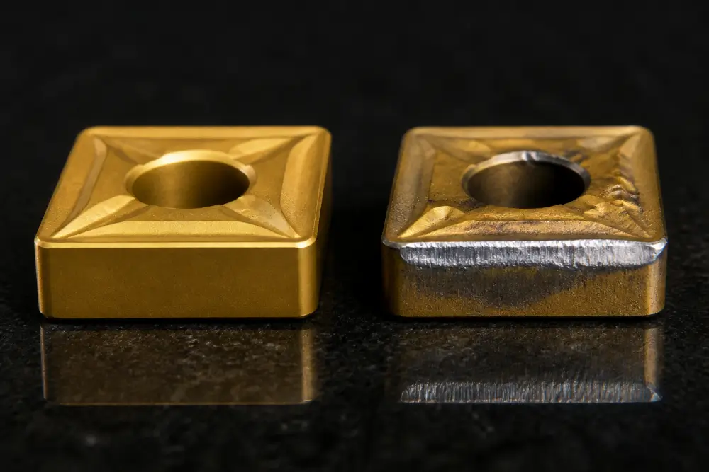
When cutting edges experience physical deterioration, the shear dynamics between the tool edge and raw stock shift. A sharp tool generates clean shear deformation across the primary shear plane at shear angles between twenty-five and thirty-five degrees. As edge degradation takes over, clean cutting action degenerates into mechanical rubbing and material plowing. The operational fallout is immediate: lateral cutting forces climb, tool deflection escalates, excessive heat transfers into the component body, and finished features drift away from blueprint specifications.
For high-precision structural parts in aerospace alloys, automotive enclosures, and robotic brackets, an unmonitored dimensional shift of 0.015 mm or a surface roughness jump beyond Ra 0.8 ruins the entire lot. When preparing parts for manufacture, executing a thorough CNC DFM review ensures that tool geometries and edge clearances match feature tolerances. At Dazao, our precision CNC machining services establish strict tooling baselines to prevent unmonitored edge decay from ever reaching customer parts.
Core Wear Morphologies: Classifying Degradation Patterns and Root Causes
Identifying the diverse types of tool wear in machining requires inspecting microscopic stress points acting on the tool matrix and coating layers. Mechanical abrasion, thermal fatigue, chemical dissolution, and adhesion each present distinct visual profiles across different alloys.
Clearance Mechanics: Flank Wear vs Crater Wear
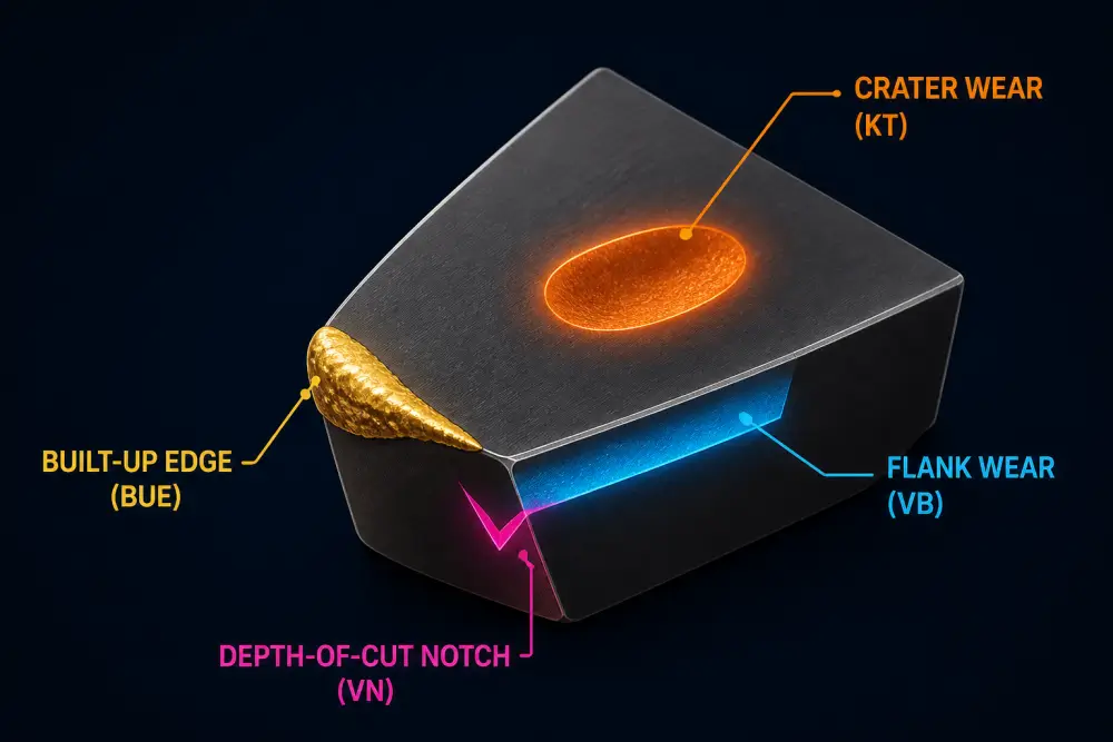
Differentiating flank wear vs crater wear is fundamental to stabilizing continuous production cells. These two failure modes appear on different tool faces, stem from distinct physical interactions, and produce completely different part failure modes.
· Flank Wear: Develops across the clearance face of the cutting insert directly adjacent to the cutting edge. This wear pattern is driven by ongoing abrasive friction against hard microscopic constituents within the workpiece, such as silicon particles in cast aluminum or iron carbides in alloy steels. As this clearance land widens, clearance relief drops to zero degrees, forcing the tool flank to rub against the freshly machined surface. Spindle load shows a predictable, linear rise, while part dimensions consistently drift positive or negative depending on external or internal cutting paths. In production cells, when flank wear land width reaches 0.3 mm on roughing tools or 0.15 mm on finishing tools, the tool must be indexed.
· Crater Wear: Forms on the rake face of the insert, positioned between 0.1 mm and 0.5 mm behind the cutting edge. This condition is caused by high-temperature chemical diffusion and molecular dissolution between the chip stream and the carbide substrate, particularly at elevated surface speeds above 180 meters per minute in steel turning or milling. As hot chips pass across the rake face at temperatures exceeding 800 degrees Celsius, iron atoms diffuse into the tungsten carbide matrix, washing out the cobalt binder phase. This carves a concave depression that deepens until the cutting edge thins out and snaps without advance warning on machine load meters.
Ductile Material Behavior: Built-Up Edge in Aluminum Machining
Managing tool wear aluminum challenges machinists with unique material behaviors. Non-ferrous alloys such as Al6061-T6 and Al7075-T6 rarely produce aggressive abrasive flank loss, yet their high ductility and low melting thresholds make them prone to severe adhesion. Matching proper aluminum CNC machining technical parameters is essential to avoiding high friction zones.
The formation of built-up edge in aluminum machining occurs when localized pressure and friction weld micro-layers of aluminum stock directly onto the carbide rake face. This material transfer takes place when cutting velocities fall below the thermal threshold needed for continuous chip formation, when tools lack polished chip flutes, or when emulsion lubricity drops below acceptable limits.
Once adhered, this welded mass acts as a false cutting tip, modifying the effective rake angle and rake geometry. Because it lacks structural stability, it periodically breaks away during the cut, tearing micro-particles of the underlying carbide substrate along with it. This cyclical welding and tearing erodes the cutting edge, producing torn surface finishes, fish-scale marks, and tall burrs along component boundaries. Applying dedicated high-speed machining aluminum strategies generates the necessary chip clearance velocity, often exceeding 600 meters per minute, to bypass this adhesion window completely.
Boundary Notch Wear and Edge Micro-Chipping
· Boundary Notch Wear: Manifests as localized V-shaped gouges at the depth-of-cut perimeter where the cutting edge meets the outer surface of the workpiece. This wear mode is common when cutting work-hardening materials like austenitic 304 or 316 stainless steels and nickel superalloys. The cold-worked boundary layer from previous passes mechanically saws into the carbide edge, generating a stress concentration zone that risks breaking the nose radius.
· Cutting Edge Micro-Chipping: Presents as small mechanical fractures along the cutting edge with dimensions from 0.02 mm to 0.1 mm. Unlike steady abrasive wear, chipping stems from dynamic shock loads during interrupted cuts, chatter from weak fixturing, spindle runout exceeding 0.005 mm, or thermal cycling.
Thermal Fatigue Cracking
Thermal cracking appears as a series of parallel microscopic fissures running perpendicular to the cutting edge. This failure mode occurs during high-speed face cuts in multi-axis CNC milling operations where flood coolant is applied inconsistently. As an insert enters the cut, temperatures at the cutting edge rise rapidly. When it exits the cut, external flood coolant quenches it back down. This continuous expansion and contraction generates internal tensile stresses that crack the carbide matrix, resulting in sudden, unexpected edge detachment.
|
Wear Pattern |
Primary Physical Driver |
Visual Indicator on Tool |
Part Quality Impact |
Primary Engineering Countermeasure |
|
Flank Wear |
Mechanical clearance abrasion |
Uniform flat wear land on clearance face |
Linear dimensional drift; gradual Ra climb |
Reduce surface speed; select harder carbide substrate |
|
Crater Wear |
High-temperature chemical diffusion |
Smooth concave pocket on rake face |
Sudden edge fracture without advance warning |
Apply thick Al2O3 coatings; lower cutting velocity |
|
Built-Up Edge |
Material adhesion and cold-welding |
Lumps of material welded to the rake face |
Cloudy, torn finishes; ragged exit burrs |
Increase cutting speed; run polished flutes; increase coolant oil ratio |
|
Notch Wear |
Severe friction against work-hardened skin |
Deep V-notch at depth-of-cut boundary line |
Step marks on side walls; localized edge shearing |
Vary depth of cut between passes; use lead angles below 45 degrees |
|
Thermal Cracking |
Rapid cyclical thermal expansion and contraction |
Comb-like parallel cracks across cutting edge |
Premature insert breakage during roughing passes |
Switch to dry milling with high-volume air blast |
Workshop Blindspots: Costly Errors Overlooked in Production
Standard machining literature assumes ideal conditions, but real-world batch production involves dynamic shop floor variables. Managing continuous production requires addressing edge failure modes that rarely appear in basic machining manuals.
Blindspot 1: The Offset Creep Trap and Feature Distortion
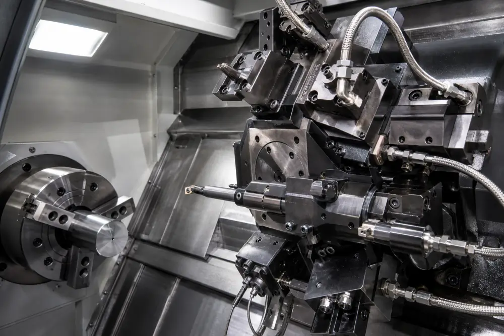
When an internal bore begins to shrink due to gradual abrasive flank wear on an indexable boring bar, the immediate instinct of an operator is often to adjust the CNC control wear offset. Shifting the wear offset outward by 0.01 mm brings the bore back within tolerance at the entrance.
However, continuing this process over tens of parts creates a severe secondary problem: the offset creep trap. While the wear offset brings the bore entry dimension back on paper, it does not reduce physical tool degradation. The tool tip has lost its original cutting clearance, raising radial tool forces significantly.
Instead of cleanly shearing material, the tool exerts massive lateral pressure on both the workpiece and the machine spindle. This elevated deflection pushes the boring bar backward during the cut. The finished bore now passes inspection at the top where tool engagement begins, but exhibits severe taper, out-of-roundness, and barrel distortion deeper in the part. In critical components requiring strict CNC tolerance and GD&T limits, this unchecked pressure ruins the geometric roundness of bearing journals.
To prevent this issue, Dazao enforces strict operating procedures: once cumulative tool wear offsets exceed 0.03 mm on precision bores, the machine flags a mandatory insert indexing requirement. Modifying software coordinates to mask worn carbide geometry is strictly forbidden.
Blindspot 2: The Secondary Deburring Cost Trap
Standard manufacturing accounting tracks insert costs as a direct tooling line item, while deburring labor is often buried under general assembly or finishing overhead. This separation leads to flawed economic decisions on the shop floor.
When a solid carbide end mill runs aluminum or low-carbon steel parts past its optimal operational window, its microscopic edge hone radius increases through micro-chipping and gentle wear. The cutter continues to hold drawing dimensions, and surface profilometers may still return acceptable Ra values along the flat floors.
However, the blunted edge transition now pushes a microscopic burr along the edge profiles of every machined slot and chamfer. A part that previously exited the machine with clean, self-breaking edges now features razor-sharp, rolled-over burrs exceeding 0.15 mm in height.
Downstream deburring times jump from thirty seconds of light wiping to four minutes of tedious hand-filing per unit. The production cell might save fifteen dollars by keeping an aging end mill on the machine for fifty more cycles, but it burns hundreds of dollars in secondary manual labor and introduces the risk of edge gouges from manual scraping tools. Managing this dynamic is vital to maintaining an efficient overall aluminum CNC machining cost balance across volume production.
Blindspot 3: Small-Tool Spindle Load Monitoring Limitations
Modern CNC machine controls offer built-in spindle load monitoring, and sales literature often suggests that setting power envelope alarms will prevent tool breakage. While this functions well for large face mills and heavy roughing tools pulling high spindle torque, it creates a dangerous blindspot when machining with micro-tooling.
When running a 1.5 mm end mill, a 2.0 mm drill, or an M3 forming tap, the cutting force generated by the tool is negligible compared to the inertia and baseline electrical draw of an 11 kW or 15 kW machine spindle. The frictional increase between a sharp micro-cutter and a completely worn cutting edge amounts to a fraction of an ampere.
The spindle load meter shows no perceptible change. By the time the load monitor detects a measurable spike, the tool has already shattered, often embedding hardened broken carbide fragments directly into high-value castings or custom manifolds.
To implement reliable CNC tool wear monitoring on sub-3mm tools, a production line must not rely on spindle load limits. The only reliable approach requires:
· Strict part counting based on physical endurance studies.
· High-magnification optical inspection at predetermined intervals.
· In-process laser tool setters to verify tool length and runout between cycles.
Warning Indicators: Sensory Signals and Downstream Part Rejections
Early detection of tool wear separates controlled precision manufacturing from unpredictable batch scrap. Operating a stable CNC cell requires tracking sensory, physical, and metallurgical indicators before edge degradation damages the workpiece.

Machine Sensory Cues and Material Deformation
Experienced machinists rely on specific signs of cutting tool wear to catch edge deterioration before out-of-tolerance conditions occur:
· Acoustic Pitch Variations: A fresh cutting edge generates a consistent, low-frequency hum indicating uniform chip shear. As clearance lands erode and frictional rubbing grows, the sound shifts to a higher-frequency harmonic squeal or a harsh vibration. This shift points to structural deflection and chatter.
· Chip Color and Shape Distortion: Chips provide direct visual evidence of edge condition. Under normal operating conditions in medium-carbon or alloy steels, the machine creates tightly curled C-shaped or helical chips with a uniform silver-straw color. As the edge dulls, friction spikes, producing dark purple or black chips with ragged, torn edges. In aluminum, wear shows up as stringy, unmanageable ribbons that wrap around tool shanks rather than snapping cleanly.
· Spindle Electrical Draw Drift: On tools larger than 6 mm, clearance wear causes a gradual, predictable increase in spindle load. A steady five to ten percent rise above baseline cutting power signals standard clearance land growth. Any sudden jump beyond fifteen percent indicates severe crater development, micro-chipping, or impending catastrophic failure.
Quality Deterioration and Geometric Out-of-Tolerance Defects
The direct tool wear effects on surface finish extend beyond cosmetics; they impact functional mechanical tolerances and sealing interfaces:
· Profilometer Traces and Ra Spikes: Clearance wear lands do not form evenly. Micro-notches and abrasive scoring marks along the tool nose radius transfer directly to the workpiece wall. A finishing pass that begins at Ra 0.4 often climbs past Ra 1.6 within twenty machining cycles if the tool nose radius loses its form.
· Thin-Wall Deflection and Dimensional Rebound: As lateral tool forces increase, the tool pushes against flexible workpiece features rather than cleanly shearing material. In thin-wall CNC machining projects, this elevated radial force causes the wall to flex outward during the pass. Once the cutter clears the feature, the material springs back, leaving the wall thicker in the center and tapered across its height.
· Heavy Exit Burrs on Critical Ports: As cutting edges transition from sharp shear cutters to blunted plowing tools, the workpiece material yields plastically instead of shearing cleanly. This displacement forms heavy edge burrs at entry and exit faces. In aerospace manifold blocks and hydraulic valve sleeves, these burrs block micro-ports, requiring aggressive manual clearing that risks damaging sealing faces.
Coolant Delivery Failures as a Wear Multiplier
Cutting fluid performance directly impacts tool longevity, especially in sticky non-ferrous alloys:
· Dilution Below Target Brix Levels: When concentration drops below six percent, the fluid loses lubricity. Workpiece material cold-welds to carbide flutes, accelerating the formation of built-up edges in aluminum and stainless alloys. Maintaining rigorous CNC coolant maintenance and concentration management prevents these lubrication failures.
· Excessive Oil Concentration: Running water-soluble fluids above twelve percent reduces cooling capacity. The mixture cannot dissipate heat away from the cutting zone quickly enough, causing high thermal gradients and thermal fatigue cracking along carbide edges.
· Recutting Suspended Chips: When wash-down nozzles fail to clear chips from deep pockets, the cutter recuts chips suspended in the cutting fluid. This introduces rapid impact shocks that chip finishing cutting edges within seconds.
Tool Life Calculation vs. Real Shop Floor Variables
Predicting insert longevity is essential for accurate cycle planning and unattended manufacturing. However, standard mathematical approximations require practical adjustments to reflect shop floor conditions.
The Classical Taylor Model and Production Limitations
In classic machining literature, the Taylor Tool Life Equation models the relationship between cutting speed and tool durability. It establishes that cutting velocity multiplied by tool life raised to an empirical material exponent equals a constant cutting speed value for a one-minute tool life.
While this model serves as a standard reference for cutting tool life calculation, practical shop results often diverge from theoretical values because the baseline equation isolates cutting speed while holding dynamic mechanical variables constant.
The following table demonstrates why real-world batch production often diverges from standard theoretical models:
|
Theoretical Assumption |
Real-World Production Reality |
Practical Impact on Tool Life |
Corrective Production Countermeasure |
|
Perfectly rigid, infinitely stiff workpiece clamping |
Thin-walled profiles flex, creating intermittent harmonic vibration |
Tool edge experiences dynamic micro-chipping, reducing life by up to 50% |
Design custom conforming soft jaws and damping fixtures |
|
Tool runout at cutting edge is zero |
Toolholder runout, collet debris, and taper wear cause runout over 0.008 mm |
Total cutting load transfers unevenly to a single flute, causing early chipping |
Enforce heat-shrink or hydraulic chucks with maximum 0.003 mm runout |
|
Raw material hardness is uniform across the lot |
Castings and hot-rolled forgings have hard outer scales and chemistry shifts |
Localized notch wear spikes at the raw material skin line |
Program dedicated roughing tools to skin the part before finishing passes |
|
Continuous uninterrupted tool contact |
Part features include cross-holes, slots, keyways, and interrupted faces |
Thermal and mechanical impacts shock the carbide substrate on every pass |
Reduce surface speed by 20% and use micro-grain carbide substrates |
Engineering Remedies for Accelerated Edge Loss
Applying effective tool wear causes and solutions requires adjustments to tool geometry, toolpath strategy, and cutting feeds:
· The Feed Rate Paradox: When faced with rapid edge wear, operators often reduce their feed rate. In austenitic stainless steels, nickel alloys, and work-hardening materials, reducing the feed rate causes severe damage. Dropping the feed per tooth below 0.05 mm forces the cutting edge to rub directly against the strain-hardened layer left by the previous tooth. The correct response is often to maintain or slightly increase the feed rate to cut beneath the work-hardened skin while reducing the surface cutting speed by fifteen to twenty-five percent.
· The Tool Overhang Ratio: Tool deflection increases with the cube of the unsupported length of the cutter. A tool operating at an overhang ratio of 5:1 experiences more than eight times the static deflection of an identical cutter set at 3:1. When handling deep cavities or complex pockets, following proven guidelines for deep pocket CNC machining setups helps stabilize tool shanks and suppress vibration. Operators must clamp tools to the shortest possible gauge length, selecting necked or tapered-core cutters when deep cavity access is required.
Preventive Protocols: Procurement Auditing and Process Control
To deliver reliable, low-cost precision parts, a manufacturing facility must manage CNC tool life through standardized operating procedures rather than operator guesswork.
Dazao Tool Life Management Framework
At Dazao, our production processes operate on standardized protocols to prevent edge degradation from causing dimensional non-conformance:
· The 80-Percent Safe Life Baseline: We do not run indexable inserts or solid carbide cutters to their theoretical breaking point. Production baseline studies determine the mean time between dimensional shifts for each alloy family. We mandate tool changes at eighty percent of that cycle count. The remaining twenty percent serves as a safety buffer against unexpected raw material hardness variations.
· Cascaded Tool Downgrading: Premium carbide cutters that reach their wear limit on high-tolerance finishing passes are not discarded immediately. After optical verification, these cutters transition down to preliminary roughing operations, pocket clearing, or chamfer prep passes. This extracts full economic value from the carbide substrate without risking critical final drawing dimensions.
· Dedicated Substrate and Coating Allocation:
1. Aluminum Alloys: Uncoated, highly polished sub-micron carbide grades with twenty-degree positive rake angles, or specialized diamond-like carbon coatings to eliminate adhesion and built-up edge formation.
2. Stainless Steels: PVD TiAlN or AlTiN multi-layer coatings on micro-grain carbide, paired with edge hones prepared to thirty microns to resist notch formation.
3. Structural Steels: High-toughness CVD TiCN-Al2O3 coated inserts featuring molded chipbreakers to control chip curl and manage thermal diffusion during heavy roughing.
Procurement Supplier Audit: Essential Tool Management Questions
When auditing a precision CNC supplier for medium-to-high volume production, engineering and procurement managers should evaluate their tool-wear management processes:
· How do you calculate tool replacement intervals on critical features?
If the supplier claims their operators change tools based on sound or visual surface inspection, their process relies on reactive intervention. Look for clear, documented part counters built directly into CNC part programs that halt the cycle when predetermined life limits are reached.
· What is your hard limit for CNC wear offsets before requiring a physical insert change?
Capable facilities establish written standard operating procedures governing the maximum allowable wear offset, such as limiting diameter offsets to 0.03 mm maximum on precision bores. This prevents operators from relying on excessive offsets that lead to out-of-round features and deep bore taper.
· What offline edge inspection equipment supports your shop floor?
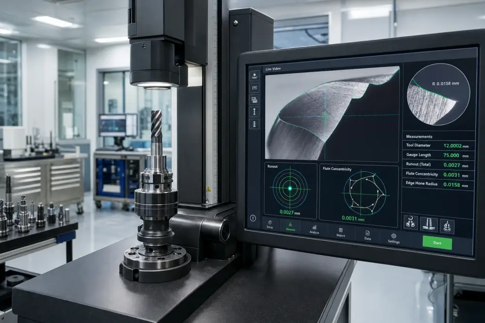
Ask to see their optical tool presetters and inspection microscopes. A qualified production facility measures tool runout, flute concentricity, and edge hone radii before loading cutting tools into the machine spindle.
· How do you control coolant concentration across machine cells?
Request to review their weekly refractometer tracking logs. Shops that monitor and log cutting fluid concentration prevent sudden built-up edge spikes, irregular insert wear, and ruined surface finishes across large volume runs.

FAQs
01.Why does chasing CNC wear offsets create tapered bores?
02.How does coolant dilution trigger sudden built-up edge in 6061 aluminum?
03.Why do machine spindle load monitors fail to protect micro-tools?
04.How does squeezing extra parts from a dull tool destroy deburring budgets?
05.Why does reducing feed rates accelerate wear in stainless steel?
06.What causes theoretical tool life calculations to fail during batch runs?





