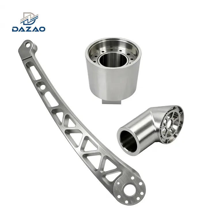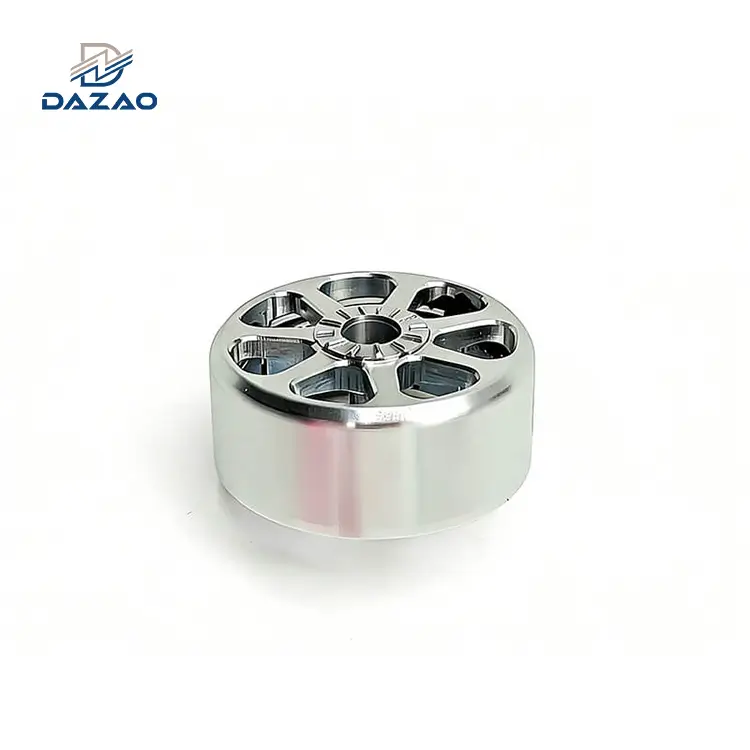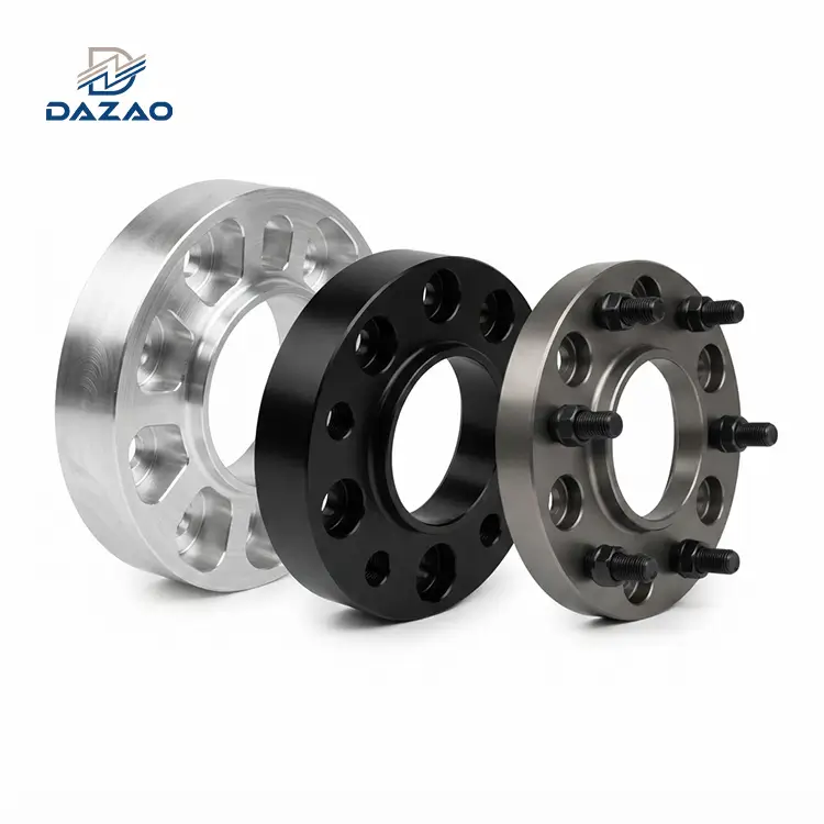

Specifying anodic surface conversion for precision CNC components requires balancing microhardness, dielectric breakdown, color saturation, and fatigue life against unit manufacturing costs. Because anodic oxide growth consumes substrate aluminum while building outward, dimensional tolerances change significantly across internal and external features. Internal bearing bores contract by the full thickness of the coating, external shafts expand by the equivalent value, and threaded pitch lines experience geometric interference governed by flank angles. Precision feature success demands rigorous tolerance offsets during CNC programming or dedicated masking protocols.
Aluminum Anodizing Engineering Guide: Types, Thickness Tolerances, Color Consistency & Masking Specifications
Precision CNC machining delivers parts with micron-level tolerances, but surface finishing often introduces unpredictable variables. The process of anodizing aluminum is not an additive cosmetic finish like powder coating or physical vapor deposition. It is an electro-chemical conversion process that converts the surface of aluminum alloys into a hard, porous, non-conductive layer of aluminum oxide.
When engineering teams specify anodic coatings without accounting for base metal cutting parameters and metallurgy, assemblies encounter severe geometric interference. To establish reliable manufacturing baselines, engineers should review standard production practices detailed in our aluminum CNC machining guide. This aluminum anodizing guide defines the mechanical, dimensional, and chemical parameters required to specify anodized aluminum parts correctly across automotive, robotics, aerospace, and semiconductor applications.
Engineering Post-Mortem: Why Anodizing Deviations Cause Assembly Failures and Dimensional Scrap
In high-mix, low-volume CNC production, surface finishing accounts for nearly thirty percent of post-machining scrap. Most of these rejections stem from an incorrect understanding of anodic film formation:
1. Fastener Galling and Cold-Welding Seizure: Assembling stainless steel screws into anodized internal threads without anti-seize paste causes immediate thread galling. The microscopic hardness of the aluminum oxide coating combined with geometric thread shrinkage creates extreme friction, mechanically locking the threads. Attempting extraction shears the screw head, destroying the machined component.
2. Inter-Batch Color Drift: Machined assemblies combining extruded Al6061 mounting plates, forged Al7075 structural links, and cast Al5083 tool plates display severe color mismatches even when dipped in the exact same dye bath. Differences in silicon, copper, and zinc concentrations change the optical refractive index of the oxide cell, turning uniform assemblies into mismatched components.
3. Unintended Dielectric Isolation: Aluminum oxide is an electrical insulator with a dielectric breakdown strength exceeding one thousand volts at fifty microns thickness. When chassis designs rely on internal mounting faces for grounding or electromagnetic shielding, uncontrolled anodizing cuts electrical continuity. Post-process mechanical scraping of the anodized layer exposes raw aluminum to galvanic corrosion and produces uneven grounding pads.
4. Bore Clamping and Hoop Stress Failures: Press-fit bearing bores specified with tight ISO H7 tolerances will shrink significantly when treated with a heavy hardcoat. Inserting a precision bearing into an uncompensated, anodized bore drives hoop stress past the yield strength of the material, cracking thin-walled housings or pinching the internal bearing race, leading to immediate rotational binding.
Root Cause Analysis: How Unspecified Plating Allowances Scrapped 120 Robotic Links at Dazao
During an early production run at Dazao, where our facility delivers high-precision CNC machining services with integrated surface treatments, our engineering department manufactured one hundred and twenty sets of robotic articulation links machined from billet Al6061-T6.
The customer drawing specified an internal bearing bore of twenty-eight millimeters with a tolerance band of plus twenty-one microns and minus zero microns to accept an angular contact bearing. The title block contained an incomplete finish note specifying hard anodize at fifty microns thickness in black.
The drawing omitted the anodizing drawing callout clarifying whether the bore tolerance applied before or after coating. The CNC milling department machined the bore to twenty-eight millimeters and twelve microns, dead center within the tolerance band. The external finishing supplier applied a nominal fifty-micron Type III hardcoat. Because Type III hardcoat builds outward by approximately twenty-five microns per surface, the internal diameter closed by fifty microns across both opposing walls.
The resulting pre-plating machined bore diameter of twenty-eight millimeters and twelve microns was reduced by the fifty-micron outward physical growth, leaving a final post-anodizing bore diameter of twenty-seven millimeters and nine hundred and sixty-two microns. This left the bore thirty-eight microns below the minimum allowable specification.
When the assembly department attempted to install the bearings, the press force exceeded twelve kilonewtons, scoring the bearing cups. The customer requested chemical stripping of the hardcoat using a hot sodium hydroxide caustic bath. While sodium hydroxide strips the aluminum oxide film, it also attacks the underlying bare aluminum substrate. Once stripped, the bore diameters measured twenty-eight millimeters and sixty-two microns, far exceeding the upper tolerance limit.
All one hundred and twenty components, valued at fourteen thousand two hundred dollars in machining time, were scrapped. Following this incident, Dazao instituted a mandatory manufacturing protocol: every internal drawing must specify pre-machining dimensions alongside post-finish requirements, or explicitly mandate thread and bore masking.

Comparative Evaluation of Anodizing Processes: MIL-A-8625 Type I, Type II, and Type III Hardcoat
Selecting the correct process from the recognized types of aluminum anodizing requires matching functional mechanical stresses against environmental exposure and dimensional tolerances. When weighing options between chemical passivation, micro-arc oxidation, or standard electro-chemical conversion, engineers should review the comparative selection criteria in our aluminum surface finishing guide. The global manufacturing sector operates primarily under the military specification MIL-A-8625 or its international equivalent, ISO 7599 and ISO 10074.
Type I: Chromic Acid Anodizing
Type I processes utilize an electro-chemical bath of chromic acid, forming an ultra-thin film ranging from half a micron to two and a half microns.
The thin layer does not measurably alter close tolerances, making pre-machining offsets unnecessary. An essential mechanical advantage is that Type I induces almost zero reduction in the fatigue strength of the alloy. Chromic acid residues trapped in structural micro-cracks or deep blind features are non-corrosive to aluminum. However, it delivers poor wear resistance and low abrasion durability. Due to environmental directives targeting hexavalent chromium compounds, Type I is restricted primarily to military aircraft components, thin-gauge structural stampings, and fatigue-critical aerospace joints.
Type II: Standard Sulfuric Acid Anodizing
The primary process in modern manufacturing, Type II operates in an agitated fifteen to twenty percent sulfuric acid bath maintained between eighteen and twenty-two degrees Celsius under a current density of twelve to fifteen amps per square foot.
It produces coating thicknesses from eight to twenty-five microns. The resulting hexagonal pore structure possesses high capillary attraction, making it suitable for organic or inorganic dyeing. Passed under ASTM B117 salt spray testing, sealed Type II films deliver between three hundred and thirty-six to over one thousand hours of continuous salt fog exposure resistance depending on alloy purity.
Type III: Hard Anodizing Aluminum Parts (Hardcoat)
Type III anodizing produces heavy-duty industrial wear surfaces. It requires an acidified sulfuric acid electrolyte kept at lower operating temperatures, typically between minus two and positive four degrees Celsius, driven by high current densities between twenty-four and thirty-six amps per square foot and elevated voltages up to one hundred volts. The process of hard anodizing aluminum parts through this low-temperature method yields an exceptionally dense structural matrix.
It generates dense coating thicknesses from twenty-five to seventy-five microns, with fifty microns representing the global engineering standard. Microhardness reaches between four hundred and five hundred and twenty Vickers, providing high scratch and sliding-wear resistance. It also exhibits high breakdown isolation, insulating against voltages from eight hundred to over two thousand volts direct current depending on thickness and sealing status.
Technical Selection: Evaluating Wear Resistance, Dielectric Breakdown, and Color Limitations
Evaluating Type II vs Type III anodizing requires evaluating three parameters: cellular morphology, microhardness, and coloration capability.
1. Cellular Morphology and Abrasion Rates:
Type II coatings have wider hexagonal pore diameters near twelve nanometers with thinner barrier cell walls near ten nanometers. This structure accepts dyes quickly but exhibits lower structural shear resistance under abrasive loads. Type III hardcoat baths, operated near freezing, slow chemical dissolution by the acid while driving rapid electro-chemical growth. This forms tightly packed cells with small pore diameters near five nanometers and thick cell walls near thirty nanometers. Under Taber Abrasion testing with a CS-17 wheel and one thousand grams of load over ten thousand cycles, Type III Al6061-T6 hardcoat loses less than fifteen milligrams of material, whereas Type II loses between thirty-five and fifty milligrams under identical conditions.
2. Optical Limitations: Clear Anodizing vs Black Anodizing on Hardcoat:
Type II produces an optically transparent oxide column on low-silicon, low-copper alloys like Al6063 and Al6061, allowing crisp clear anodizing vs black anodizing and bright shades of red, blue, or gold. Type III hardcoat produces a naturally dark, dense structure. On Al6061, fifty microns of un-dyed hardcoat appears dark bronze-gray; on Al7075, it takes on an olive-tinted brownish-gray cast. Because the base oxide is naturally dark, bright colored dyes cannot be absorbed effectively. Industrial components treated with Type III coatings are therefore limited to natural dark bronze or dye-saturated black.
3. Fatigue Life Penalty:
The extreme hardness of a fifty-micron Type III coating introduces significant residual tensile stress at the substrate interface. Micro-cracks naturally present within the hardcoat layer act as stress risers under cyclic mechanical loading. Specifying fifty microns of hardcoat on Al7075-T6 or Al6061-T6 reduces the base material fatigue limit by twenty to forty percent. For dynamic load components such as rotating shafts, high-speed automated linkages, or drone propeller hubs, engineering drawings should balance wear requirements against fatigue life, often capping thickness at twenty-five to thirty microns or calling for post-anodize shot-peening treatments.
Coating Thickness Selection Matrix Across Industrial Applications
The following aluminum anodizing thickness chart provides engineering baselines across standard industrial applications:
|
Anodizing Process (MIL-A-8625) |
Nominal Film Thickness (µm) |
Dimensional Growth per Surface (µm) |
Vickers Hardness (HV 0.05) |
Dielectric Breakdown (V) |
Common Industrial Applications |
|
Type I (Chromic Acid) |
0.5 – 2.5 µm |
~0.25 – 1.25 µm |
180 – 220 HV |
< 100 V |
Aircraft wing ribs, structural bulkheads, precision optical mounts |
|
Type II Class 1 (Clear) |
8 – 15 µm |
~4 – 7.5 µm |
250 – 320 HV |
200 – 400 V |
Semiconductor chassis, robotic covers, medical enclosure frames |
|
Type II Class 2 (Colored) |
12 – 25 µm |
~6 – 12.5 µm |
280 – 350 HV |
200 – 600 V |
Consumer electronics, automotive engine covers, drone arms |
|
Type III Class 1 (Hard Clear) |
25 – 50 µm |
~12.5 – 25 µm |
400 – 480 HV |
800 – 1500 V |
Hydraulic pump bodies, pneumatic cylinders, linear slide rails |
|
Type III Class 2 (Hard Black) |
40 – 65 µm |
~20 – 32.5 µm |
420 – 520 HV |
1000 – 2000 V |
Defense slide rails, subsea sensor housings, high-wear conveyor tracks |
|
Type III (Heavy Build-up) |
65 – 100 µm |
~32.5 – 50 µm |
380 – 450 HV |
> 2000 V |
Worn journal repair, downhole drilling subs, electrical isolation bushings |

Dimensional Growth Mechanics: Managing Anodic Build-Up Across Precision CNC Tolerances
The most frequent point of confusion among design engineers is the physical growth pattern of the anodic layer. Plating processes deposit material exclusively outward onto the surface.
The phenomenon of anodizing dimensional change CNC parts behaves differently: the oxide layer converts base aluminum atoms in place, drawing oxygen from the electrolyte bath.
When planning multi-axis machining operations, managing these dimensional growth variables must align with the strict geometric dimensioning guidelines found in our CNC tolerance design and GD&T manual.
The 50/50 Growth Rule: Substrate Consumption vs. Outward Ceramic Expansion
Because one volume unit of metallic aluminum converts to approximately one point six volumes of aluminum oxide, the newly created ceramic matrix expands beyond the original boundary:
· Penetration Depth: Fifty percent of total coating thickness forms below the original surface line, consuming base material.
· Build-Up Thickness: Fifty percent of total coating thickness expands outward, beyond the original pre-machined contour.
For an engineer designing a part requiring a fifty-micron Type III hardcoat, the actual outward material growth per treated surface is twenty-five microns.
Cylindrical Feature Shifts: Internal Bore Shrinkage vs. External Shaft Growth
Calculating the net impact of the fifty percent build-up factor across typical CNC machined geometries:
· External Diameters (Shafts, Bosses, Locator Pins):
External boundaries grow outward across both opposing surfaces. The final outer diameter equals the pre-plated diameter plus the full nominal coating thickness. For example, a thirty-millimeter shaft treated with fifty microns of hardcoat expands to thirty millimeters and fifty microns.
· Internal Diameters (Bearing Bores, Dowel Pin Pockets):
The cylindrical walls grow toward the centerline from both sides, shrinking the opening. The final inner diameter equals the pre-plated diameter minus the full nominal coating thickness. A thirty-millimeter bore treated with fifty microns of hardcoat shrinks to twenty-nine millimeters and nine hundred and fifty microns.
· Linear Spacing, Slot Widths, and Pocket Depths:
For open step heights or isolated pocket depths where one reference floor is anodized, the shift equals half of the nominal coating thickness. For an internal slot with two opposing faces growing toward each other, the effective slot width decreases by the full nominal thickness.
Electric Field Concentration: Preventing Corner Spalling via the 0.5 mm Edge Radius Standard
A recurring cause of rejection on Type III hard-anodized parts is corner chipping, flaking, or burn-off on sharp outside edges. During the electrolytic reaction, electric field lines concentrate heavily around sharp ninety-degree outer edges. This spike in local current density causes significant heating and excessive oxide growth.
Because aluminum oxide grows perpendicular to the substrate surface, two competing growth fronts collide at a sharp ninety-degree corner. This collision creates a void-filled, highly brittle plane running outward at a forty-five-degree angle. Under light mechanical contact or assembly clamping, this unsupported edge shears off, exposing the bare substrate.
To prevent edge spalling, mechanical designers should apply the practical edge-break strategies in our aluminum part deburring manual. Dazao design rules require:
· For Type II coatings up to twenty microns: Break all sharp edges with a minimum chamfer or radius of zero point two millimeters.
· For Type III coatings between twenty-five and fifty microns: Break all sharp outside corners with a minimum radius of zero point five millimeters, with one millimeter preferred. Avoid sharp ninety-degree intersections entirely.
Machining Compensation Protocol: Holding an H7 Bore Tolerance Under 40 µm Hardcoat
A design calls for a linear guide carriage block machined from Al6061-T6, containing a twenty-five-millimeter bore designed for an H7 press-fit tolerance of plus twenty-one microns and minus zero microns. The drawing specifies a Type III hardcoat thickness of forty microns plus or minus five microns to provide wear resistance against environmental grit.
Step 1: Establish the Nominal Coating Impact
A forty-micron nominal film thickness generates twenty microns of internal penetration and twenty microns of outward growth per surface. This produces a total diametrical bore shrinkage of forty microns.
Step 2: Calculate the Target Pre-Machined Machining Window
To ensure the finished bore falls between twenty-five millimeters zero microns and twenty-five millimeters twenty-one microns after anodizing, the lower machining threshold must be set to twenty-five millimeters and forty microns, while the upper machining threshold must be set to twenty-five millimeters and sixty-one microns.
Step 3: Production Floor Execution at Dazao
The CNC milling technician sets the boring bar tool compensation to target twenty-five millimeters and fifty microns plus or minus five microns. Once processed through the hardcoat bath with forty microns applied, the bore closes by forty microns. The pre-treatment bore of twenty-five millimeters and fifty microns contracts to twenty-five millimeters and ten microns. The finished feature sits dead-center within the customer specified tolerance band, eliminating post-plating scrap or secondary reaming.
Hidden Anodizing Pitfalls: Factory-Floor Failure Modes and Preventative Protocols
Standard finishing handbooks focus almost entirely on tank bath chemistry while ignoring component-level mechanical failures. At Dazao, our engineering and quality teams have documented three recurring defect modes that lead to component scrap across the precision CNC sector.
Entrapped Acid Bleed-Out: Chemical Causes and Ultrasonic Neutralization in Blind Holes
Blind threaded holes create microscopic fluid reservoirs. During the anodizing cycle, components cycle through concentrated sulfuric acid baths containing one hundred and fifty to two hundred grams per liter of acid under pressures driven by tank depth and agitation.
Because surface tension prevents standard immersion rinses from exchanging fluid inside narrow blind cavities, residual acid remains trapped behind air pockets at the bottom of the threads.
When the part enters the hot sealing tank near one hundred degrees Celsius, thermal shock caps the outer pore cells, trapping the boiling acid inside the blind root. Three to five days later, during warehouse storage or final customer assembly, the residual acid slowly weeps outward along the root flank. This weeping produces an unremovable, powdery white bloom of aluminum sulfate salt that corrodes adjacent mating surfaces and strips dyed colors.
Dazao Shop-Floor Countermeasures:
· Design Depth Rules: Limit blind tapped hole depths to a maximum of two and a half times the major diameter unless a relief cross-hole is engineered into the design.
· Ultrasonic Pulsed Neutralization: All components with blind internal threads must pass through an agitated deionized ultrasonic rinse, followed by a warm three percent sodium bicarbonate neutralization soak, capped by high-pressure compressed air evacuation at six bar prior to hot water sealing.
Thread Flank Geometric Interference: Why 60° Angles Multiply Pitch Line Build-Up by 4x
A common calculation error occurs when engineers assume a fifty-micron Type III hardcoat simply reduces the minor diameter of an internal thread by the standard outward build-up thickness of twenty-five microns. This assumption ignores the sixty-degree included flank angle of standard ISO metric threads.
To prevent fastener binding, machinists must adjust root and pitch parameters according to the internal tapping parameters detailed in our CNC thread design guide.
Because anodic oxide grows perpendicular to every exposed surface, the coating forms simultaneously along both opposing thirty-degree flank angles. The outward build-up per flank surface equals half the nominal film thickness. Projecting this normal growth onto the pitch line requires dividing by the sine of thirty degrees. Because the sine of thirty degrees is zero point five, the pitch line shift per flank equals the nominal film thickness. When accounting for both opposing flanks across the diameter, the total effective pitch diameter reduction equals two times the total nominal coating thickness.
For a fifty-micron Type III hardcoat, the effective pitch diameter of an internal thread decreases by one hundred microns. For an M3 by zero point five thread, the total allowable pitch diameter tolerance band for a 6H class is only eighty microns. An unmasked, uncompensated fifty-micron hardcoat reduces the pitch diameter by more than the entire tolerance window, ensuring stainless steel fasteners seize within the first two turns.
Dazao Shop-Floor Countermeasures:
· Mandatory Masking Threshold: All internal threads M5 and smaller scheduled for Type III hardcoat must be plugged using silicone masking inserts.
· Oversized Pre-Tapping: For high-density electronic chassis where masking hundreds of small holes is cost-prohibitive, Dazao implements oversized taps with pitch diameter offsets between fifty and one hundred microns during CNC machining to absorb the four-fold flank growth.
Galvanic Robbing in Shared Baths: Controlling Over-Burn in Mixed Al6061 and Al7075 Batches
Subcontract finishing shops often group different aluminum alloys on the same titanium rack or in the same tank to meet minimum batch weights. Mixing Al6061-T6 and Al7075-T6 on a single flight bar creates immediate electrochemical imbalance.
Al7075 contains high concentrations of zinc up to six point one percent and copper up to two percent, which significantly lower its electrical resistivity compared to silicon-magnesium balanced Al6061. Under constant-current rectification, the lower-resistance Al7075 components draw disproportionate current density.
The Al7075 parts overheat locally, suffering edge dissolution and burning, while the adjacent Al6061 components receive insufficient current, resulting in thin, soft coatings that fail pin-abrasion testing.
Dazao Shop-Floor Countermeasures:
· Strict Alloy Segregation: Different alloy series are never loaded onto the same rack or processed in the same bath.
· Current-Density Recalibration: Al7075 production runs require dedicated chilling down to minus two degrees Celsius to control boundary layer temperatures, while Al6061 runs operate safely between positive two and positive four degrees Celsius.

Feature Isolation Strategies: CNC Machining Allowances vs. Precision Masking Operations
Controlling critical tolerances requires choosing between upfront CNC machining compensation and mechanical masking. Each approach carries specific trade-offs regarding tooling expense, labor time, and inspection yield, which can be evaluated alongside the design fundamentals covered in our aluminum CNC machining design guide.
Internal Thread Processing: Tapping Tolerances vs. Silicone Plug Masking Protocols
For anodizing masking threaded holes, the mechanical threshold centers around thread pitch and diameter:
· M6 and Larger Under Type II Processes: Masking is generally unnecessary. Standard 6H taps provide enough clearance to absorb ten to fifteen microns of Type II film growth without exceeding torque limits.
· M5 and Smaller Under Type II Processes: Use high-limit taps with an oversize pitch diameter offset. If standard 6H taps are used, apply silicone threaded plugs.
· All Threads Under Type III Hardcoat: Mechanical masking is mandatory. If masking is impossible due to internal access restrictions, cut threads using custom-ground taps with an explicit pitch diameter offset calculated by doubling the nominal thickness and dividing by the sine of the flank half-angle.
Press-Fit Bearing Bores: Comparing Dedicated Masking Plugs with Secondary Reaming
Machining an ISO H7 bore presents distinct challenges for surface finishing:
· Strategy A: CNC Pre-Machining Offset:
The CNC machine bores the feature oversize by exactly the expected diametrical reduction of the full nominal film thickness. This delivers zero post-processing labor while ensuring protective hard oxide covers the entire bore surface. However, the anodizer must maintain film thickness within an extremely tight three-micron window across the entire flight bar, requiring advanced process monitoring.
· Strategy B: Mechanical Masking via Pull-Plugs:
Tapered EPDM or precision-ground silicone plugs protect the bore throughout etching and anodizing. The bore maintains original machined tolerances within five microns and remains free of oxide build-up. However, manual masking adds labor expense, and the untreated bare metal remains susceptible to atmospheric galvanic corrosion if steel bearings contact raw aluminum in damp environments.
· Strategy C: Post-Anodize Secondary Machining:
The part undergoes full hardcoat without bore masking, leaving zero point one millimeters of stock on the diameter. A polycrystalline diamond reamer or internal grinding wheel cuts the bore to final H7 size post-coating. This guarantees bore roundness and positional true position under five microns regardless of tank variables. However, specialized tooling is required to cut through high-hardness oxide, and transitions between raw aluminum and hardcoat edges are prone to micro-chipping.
Electrical Grounding Pads: Masked Chem-Film Conversions vs. Mechanical Fixture Isolation
Aluminum chassis for avionics and robotics require distinct, highly conductive metal pads for electrical ground returns. Because anodizing creates a durable electrical insulator, these grounding pads must be protected:
1. Precision Masking Fixtures: Reusable bolted masking fixtures with fluoroelastomer gaskets seal grounding pads against electrolyte ingress.
2. Dual-Surface Finishing Combining Anodize and Chem Film:
The entire part is first processed with clear or yellow chromate conversion coating under MIL-DTL-5541 Type II Class 3, which maintains low surface contact resistance below five thousand micro-ohms per square inch. The grounding pads are then masked with die-cut vinyl adhesive tape, and the remaining component undergoes structural Type II or Type III anodizing. This process delivers environmental protection across the exterior body while retaining electrical conductivity on specified grounding lands.

Surface Aesthetics and Optical Performance: Clear vs. Black Anodic Dye Formulations
Surface aesthetics across high-end consumer hardware, surgical optics, and automotive interiors depend heavily on electro-chemical parameters. Clear anodizing preserves the natural sheen of the metal, whereas black anodizing absorbs visible light through saturated organic or inorganic dye chemistry.
Substrate Composition, Media Blasting, and Sealing Variables Driving Inter-Batch Shift
Maintaining color uniformity across multiple production lots requires controlling four specific variables:
1. Base Alloy Chemistry and Intermetallic Phases
The presence of alloying elements alters oxide clarity and dye uptake:
· Al1xxx Series: Delivers mirror-clear finishes with high metallic reflectivity.
· Al5xxx Series: Delivers clear, bright satin finishes preferred for consumer enclosures.
· Al6061: Offers neutral clear coatings and accepts deep black dyes uniformly.
· Al7075: Creates a distinct yellow-bronze cast that shifts black dyes toward a muted, greenish-brown hue.
· Al2024: Produces a muddy gray-brown baseline with poor, patchy dye absorption.
Due to the intermetallic copper compounds present in Al7075 and Al2024, these alloys should not be paired with Al6061 on the same visible exterior assembly if identical color matching is required.
2. Mechanical Pre-Treatment Consistency
Variations in surface finish directly shift optical reflectivity. To prevent visual mismatches, surface roughness must stay within target parameters, matching the surface profile specifications outlined in our CNC surface roughness chart.
Sandblasting media must be tightly monitored. Fresh number one hundred glass beads produce a diffuse matte appearance, but as the glass breaks down into fine dust over fifty operating cycles, the resulting surface texture shifts toward a semi-burnished sheen. This shift causes parts run through identical dye tanks to appear noticeably different in tone. Dazao quality standards require sandblasting media charge levels to be audited every forty production hours to maintain a stable surface profile between Ra 1.6 and 2.2 microns.
3. Film Thickness Variations
In colored Class 2 anodizing, deeper oxide columns hold greater dye volume:
· Film thickness of ten microns: Produces light saturation that appears washed out or dark gray.
· Film thickness of twenty microns: Produces full optical saturation that yields a deep black.
· Thickness drift of five microns across an oversized part creates noticeable color gradients across continuous faces.
4. Sealing Methodology
· Mid-Temperature Nickel Acetate Sealing between seventy-five and eighty-five degrees Celsius: Delivers dye retention without surface smudging, making it preferred for optical black parts.
· Boiling Deionized Water Sealing between ninety-six and one hundred degrees Celsius: Environmentally compliant, but creates a microscopic chalky haze on the exterior surface if bath pH drifts outside the five point five to six point five window.
Objective Spectrophotometer Inspection: Establishing Industrial Delta E Color Limits
To eliminate subjective visual disagreements, Dazao implements industrial spectrophotometer inspections under standard D65 illumination in accordance with ISO 7724 and ASTM E308:
|
Color Matching Tier |
Allowable Delta E (ΔE*ab) |
Practical Industrial Application |
|
Tier 1: Critical Cosmetic |
Less than 0.8 |
Consumer electronics housings, high-visibility cockpit instruments |
|
Tier 2: Standard Industrial |
Less than 1.5 |
Automotive brackets, industrial robotic arms, high-mix subsea housings |
|
Tier 3: Functional / Hidden |
Less than 3.0 |
Internal motor mounts, hidden structural brackets, fluid manifolds |
Engineering Drawing Callouts: Structuring MIL-Spec and ISO Documentation Without Ambiguity
Vague engineering notes frequently lead to supplier misinterpretations, dimensional scrap, and delivery delays. A production-ready drawing callout must define the standard, type, class, coating thickness, dimensional limits, and clamping boundaries.
Standard Industry Specifications Reference
· MIL-A-8625F: Anodic Coatings for Aluminum and Aluminum Alloys.
· ISO 7599: Anodizing of aluminum and its alloys for clear and colored decorative coatings.
· ISO 10074: Specification for hard anodic oxidation coatings on aluminum and its alloys.
· AMS 2469 and AMS 2472: Aerospace Material Specifications for hard and general sulfuric anodizing.
Defining Dimensional Boundaries: Before-Coating vs. After-Coating Drafting Syntax
Engineering drawings must eliminate dimensional ambiguity by including one of the following explicit statements:
· Option A (Industry Preferred): All dimensions and tolerances apply after final surface treatment. This requires the CNC machining supplier to calculate and apply all pre-machining allowances.
· Option B: All dimensions and tolerances apply before surface treatment, with final coating thickness to be added. This places control of nominal component growth on the engineering design team.
If your engineering group requires assistance establishing these tolerance allowances, you can consult directly with our application engineers for DFM feedback during CAD review.
Electrical Contact Planning: Designating Permitted Rack Mark Zones on Non-Critical Faces
Anodizing requires a secure mechanical and electrical connection to suspend the part in the electrolyte bath. Because current flows directly through the titanium or aluminum rack contact point, the contact area receives no coating and leaves bare base metal exposed.
If a technician clamps a spring contact onto an O-ring groove, an internal bore, or a primary visible face, the clamp point will create an un-anodized leak path or visual defect. Engineering drawings must designate specific non-critical zones, stating that permitted rack marks must be restricted to designated areas with zero contact marks allowed on functional sealing features and internal bores.
Quality Inspection Protocols: Eddy-Current Gauging, Acid Dissolution, and Salt Spray Testing
· Thickness Verification under ASTM B244: Non-destructive eddy-current testing across a minimum of five distributed points per component.
· Sealing Quality under ASTM B680: Acid dissolution weight-loss testing verifying pore hydration without surface smudging.
· Corrosion Resistance under ASTM B117: Neutral salt spray testing verifying three hundred and thirty-six hours of exposure for Type II coatings and one thousand hours for Type III coatings with zero pitting corrosion.
Anodizing Cost Breakdown: Commercial Drivers and Design-Stage Cost Reduction
Understanding the pricing structure behind aluminum anodizing cost helps procurement teams reduce piece costs without compromising mechanical performance. To understand how finishing operations integrate into total part pricing, review our technical breakdown on managing overall aluminum CNC machining cost.
Processing Cost Drivers: Thermal Chilling, Racking Density, and Manual Masking Labor
1. Coating Type Selection:
Type III hardcoat typically carries a forty to eighty percent price premium over Type II. This cost difference stems from lower tank throughput, longer bath times, and high electrical power consumption required by high-output direct current rectifiers and commercial fluid chillers holding baths near freezing.
2. Masking Complexity and Labor Costs:
Manual masking is the largest driver of finishing costs on precision CNC parts. Inserting fifty silicone plugs into small blind holes on a complex manifold can take fifteen minutes of manual labor per part, often exceeding the cost of the anodizing bath cycle itself.
3. Custom Racking vs. Standard Spring Fixtures:
Heavy parts exceeding five kilograms or complex geometries require custom-bolted titanium tooling to maintain contact under mechanical agitation. These fixtures carry non-recurring engineering costs that must be amortized over the production run.
4. Lot Minimums and Batch Sizes:
Anodizing facilities price by the flight bar or apply minimum lot charges between one hundred and two hundred and fifty dollars per run. Running five prototype parts carries the same minimum base cost as running eighty parts that fit on the same rack.
Actionable Cost Reduction Strategies for Procurement Teams and Component Designers
|
Design Configuration |
Cost Penalty |
Engineering Alternative |
Unit Cost Impact |
|
Specifying 50 µm Hardcoat Everywhere |
High electricity and chilling costs |
Specify 15 µm Type II unless the application explicitly requires high sliding wear |
30% to 50% reduction in finishing cost |
|
Masking 20+ Blind M3 Threads |
High manual labor insertion and removal time |
Use oversized taps during CNC machining; eliminate thread masking |
Saves $0.15 to $0.40 per threaded hole |
|
Zero Specified Racking Zone |
High rework and scrap rate from clamp contact marks |
Designate explicit internal clearance holes or back faces for clamp attachment |
Eliminates 100% of aesthetic rack mark rejections |
|
Small Fragmented Batches |
Incurs tank minimum fee on every release |
Consolidate releases into uniform batch sizes matching plater bar capacity |
40% to 60% savings on net processing fees |
|
Custom Color Matching |
Specialty dye bath setup, continuous titration |
Standardize on Class 1 Clear or Class 2 Optical Black |
Eliminates custom dye setup charges |
Dazao Quality Control Protocol and Engineering Pre-Release Checklist
Ensuring predictable surface finishing requires verifying that drawing notes match production capabilities before material reaches the CNC spindle. At Dazao, our engineering reviews filter out conflicting tolerances and missing finish parameters during the DFM phase, referencing our verified CNC DFM checklist for production-ready components.
Procurement and Design Release Checklist
Before releasing aluminum component drawings to production, verify each of the following engineering checkpoints:
· Base Alloy Consistency: Is the alloy selected suitable for the chosen finish? If bright colors are required, have high-copper alloys like Al2024 and Al7075 been avoided?
· Dimensional Boundaries: Does the drawing clearly state whether all dimensions apply after surface treatment?
· Chamfers and Radii: Are all sharp exterior edges broken with at least a zero point five millimeter radius to prevent corner burn-off and coating spalling under Type III hardcoat?
· Thread Compensation Strategy: For threads M5 and smaller, has the drawing clarified whether holes should be masked with silicone plugs or tapped oversize with specialized tooling?
· Bore Tolerance Allowances: Have internal bearing bores accounted for diametrical shrinkage equal to double the outward surface growth?
· Racking Permissions: Is there an explicit drawing zone identifying acceptable rack contact marks away from functional sealing grooves and primary cosmetic surfaces?
· Process Specification: Does the callout reference an established standard like MIL-A-8625 Type III Class 2 Black with explicit thickness tolerances instead of generic text?

FAQs
01.Why do stainless steel bolts immediately seize when installed into anodized aluminum threads?
02.Can an assembly containing both Al6061 and Al7075 achieve an identical anodized color match?
03.What causes white salt-like powder to weep out of blind holes days after anodizing?
04.Can chemical stripping restore parts when hardcoat anodizing causes undersized bearing bores?
05.Should stainless steel threaded inserts like Helicoils be installed before or after anodizing?
06.How can an anodized aluminum electronics chassis maintain proper electrical grounding?