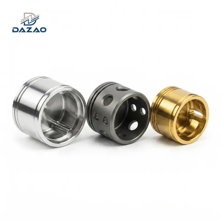

Hard coat anodizing Type III is an electrochemical ceramic conversion process rather than a mechanical deposition layer. It transforms aluminum into alpha-phase aluminum oxide, growing equally inward and outward relative to the original part boundary. Failing to account for this outward dimensional expansion leads to frozen assemblies, undersized bores, and stripped fasteners. While unsealed coatings provide peak abrasive wear resistance, they degrade substrate fatigue life significantly and risk adhesive galling against raw stainless steel. Mitigating these risks requires applying accurate pre-machining dimensional allowances, providing edge radii of at least 0.5 mm, and enforcing clear technical notes on engineering drawings.
Type III Hard Anodize vs Type II: Ceramic Conversion vs Cosmetic Plating
Treating hard anodizing aluminum as merely an extended variant of decorative Type II anodizing remains a frequent root cause of scrapped components in contract manufacturing. Standard sulfuric anodizing operates in warm electrolyte baths around 20 degrees Celsius, using modest current densities near 1.5 amperes per square decimeter to form thin, porous, decorative layers between 8 and 18 microns. In stark contrast, producing hard anodizing requires chilling the sulfuric acid bath between 0 and 4 degrees Celsius, driving current densities to 2.5 through 3.5 amperes per square decimeter, and regulating potentials up to 75 volts. Consult our detailed guide on aluminum anodizing types and thickness boundaries for fundamental process classifications.
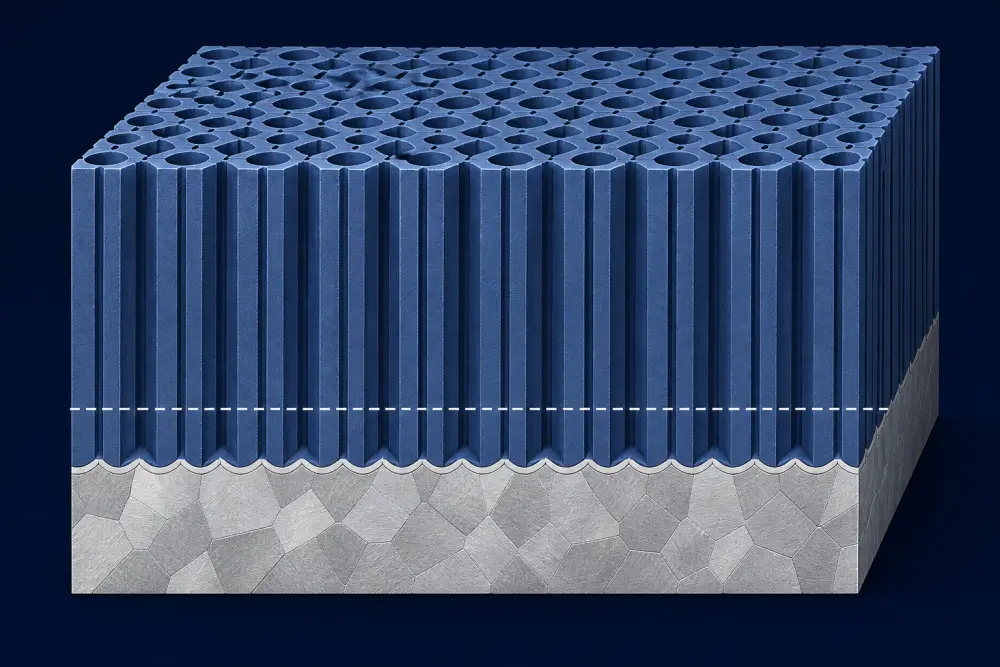
These low temperatures suppress the natural dissolution rate of the acid, enabling dense columns of crystalline and amorphous aluminum oxide to nucleate. The resulting surface forms a structural ceramic layer integrated directly with the metallic base. Reviewing aluminum CNC machining process fundamentals highlights how this thermal and chemical reaction alters baseline material performance.
At the Dazao production facility, teardown analyses of malfunctioning linear slides reveal that engineers often machine features to final print dimensions before anodizing. Immersing a precision sliding shaft in a hardcoat bath causes the diameter to grow significantly, while the matching housing bore shrinks by the same magnitude. The calculated running clearance turns into an unyielding mechanical interference fit. Type III hardcoat is an active functional modification that alters dimensional envelopes, electrical conductivity, and surface roughness.
|
Electrochemical Parameters |
Type II Standard Anodize |
Type III Hard Coat Anodize |
|
Electrolyte Bath Temperature |
18 to 22 degrees Celsius |
0 to 4 degrees Celsius |
|
Operating Current Density |
1.2 to 1.8 A/dm2 |
2.5 to 3.6 A/dm2 |
|
Maximum Terminal Voltage |
12 to 18 Volts |
Up to 75 to 100 Volts |
|
Typical Layer Thickness |
8 to 18 microns |
45 to 75 microns |
|
Cellular Pore Structure |
Wide, open pore morphology |
Dense, highly compacted cell walls |
|
Primary Engineering Intent |
Decorative tint and basic corrosion barrier |
Wear resistance, dielectric strength, sliding life |
Hard Anodize Dimensional Change: Calculating the 50/50 Growth Rule
Predicting hard anodizing dimensional change begins with understanding the dual-directional growth mechanism. The total film thickness divides into two equal fractions: 50 percent penetrates below the original surface boundary into the base metal, while 50 percent builds outward. Specifying a total hard anodizing thickness of 50 microns generates an outward physical growth of 25 microns on each coated surface.
|
Specified Total Coating |
Surface Growth per Side |
Outside Diameter (Shaft) Growth |
Inside Diameter (Bore) Reduction |
|
25 microns (0.0010 in) |
12.5 microns (0.0005 in) |
+25.0 microns (+0.0010 in) |
-25.0 microns (-0.0010 in) |
|
50 microns (0.0020 in) |
25.0 microns (0.0010 in) |
+50.0 microns (+0.0020 in) |
-50.0 microns (-0.0020 in) |
|
75 microns (0.0030 in) |
37.5 microns (0.0015 in) |
+75.0 microns (+0.0030 in) |
-75.0 microns (-0.0030 in) |
Sharp Corner Dog-Boning and Edge Radius Rules
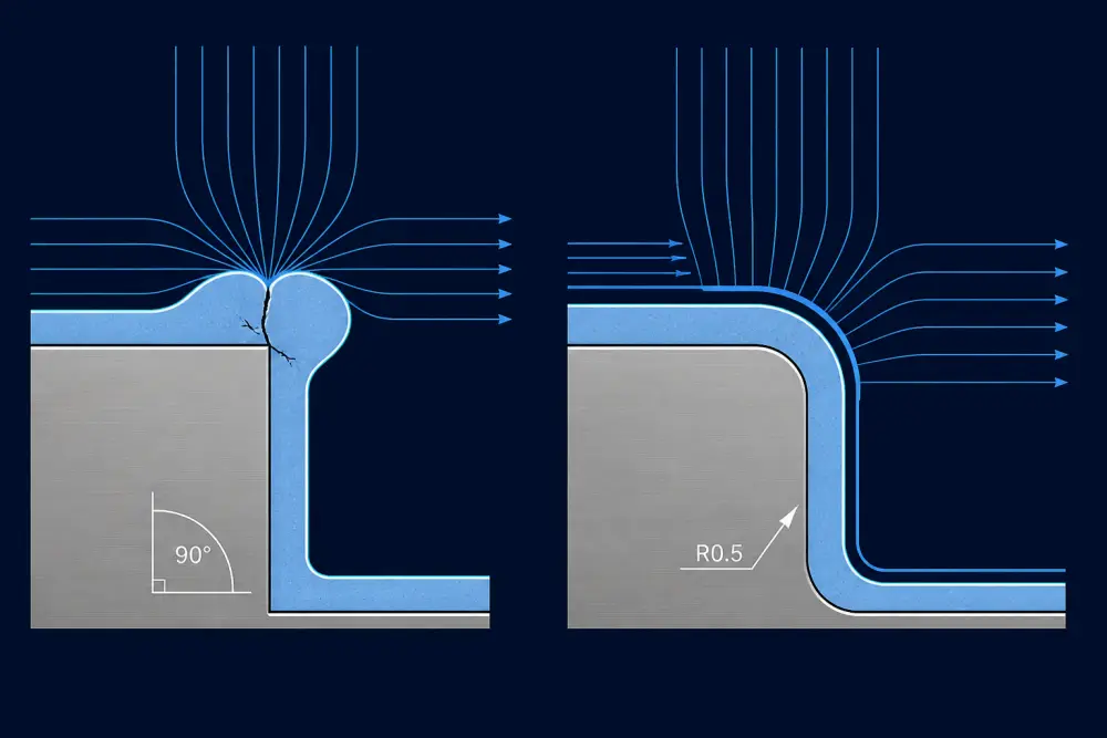
Assuming that 50/50 expansion occurs uniformly over complex geometrical profiles will cause inspection failures. On sharp 90-degree external edges, electrical field lines crowd together intensely. The coating nucleates from both adjacent perpendicular faces at once, expanding outward along a 45-degree angle.
This localized buildup forms a raised, fragile ridge commonly called dog-boning. At these sharp corners, the total thickness often reaches 130 to 150 percent of the nominal side wall specification. This raised ridge prevents components from sliding into close-fitting bores and fractures under minimal side impact, generating abrasive alumina debris. Enforcing proper edge deburring for aluminum parts and adding an external corner radius of at least 0.5 mm redistributes electrical flux lines, keeping growth uniform.
Blind Bore Current Starvation and Internal Taper Risks
While outer profiles gather concentrated electrical energy, internal features face chemical starvation. In small, blind-ended cavities, fluid circulation stops during processing. The trapped electrolyte rapidly depletes its sulfate ions, while heat from the exothermic conversion reaction cannot escape.
When the ratio of depth to diameter inside a blind bore exceeds two to one, effective current density near the floor drops toward zero. The entrance of the bore receives the specified 50 microns of hardcoat, while the deepest section receives minimal growth. This produces an unwanted internal taper that binds shafts. Rectifying this issue on manifold blocks requires mounting auxiliary titanium cathode tubes down the bore centerline alongside dedicated spargers to flush chilled acid through the cavity.
Thread Pitch Expansion and Dowel Pin Press-Fit Allowances
Because thread profiles use 60-degree flank angles, dimensional expansion is magnified geometrically. Outward growth along each flank shifts the functional pitch diameter by four times the single-surface build-up. A 25-micron build-up per face expands an external thread pitch diameter by 100 microns, while shrinking an internal thread pitch diameter by that same 100 microns.
Standard metric or unified internal threads will consistently fail go-gauge verification if tapped to normal tolerances prior to coating. Machinists must utilize oversized taps, such as GH5 or GH7 classes, to pre-compensate for this inward growth. For shafts and pins, integrating tight CNC tolerance design and GD and T principles into early models ensures proper post-coat clearance. Pressing ground steel pins into uncompensated hard-anodized bores creates immense hoop stress that shatters the unyielding alumina layer, often fracturing the surrounding aluminum housing.
Hard Anodizing Wear Resistance: Tribological Limits, Sealing & Counterface Selection
The widespread adoption of hard anodized aluminum applications stems from superior sliding durability. A properly controlled hardcoat on Al6061 achieves micro-hardness numbers between 900 and 1000 HV 0.05 (equivalent to 60 to 70 HRC), matching case-hardened steels and hard chrome plating. Standard Taber abrasion evaluations show that hardcoated aluminum loses less than 1.5 milligrams of material per 1000 cycles under a 1000-gram load with CS-17 wheels, outperforming standard Type II finishes ten times over.
|
Surface Condition |
Micro-Hardness (HV 0.05) |
Taber Wear Loss (mg / 1000 cycles) |
Dynamic Friction vs Steel (Lubricated) |
|
Bare Al6061-T6 Base Metal |
95 to 115 HV |
35 to 50 mg |
0.60 to 0.70 (Dry) |
|
Type II Anodize (15 microns) |
300 to 400 HV |
15 to 25 mg |
0.45 to 0.55 (Dry) |
|
Type III Hardcoat (Unsealed) |
900 to 1050 HV |
1.0 to 2.5 mg |
0.20 to 0.30 |
|
Type III Hardcoat (Sealed) |
700 to 850 HV |
3.0 to 5.0 mg |
0.25 to 0.35 |
|
Hard Chrome Plating |
950 to 1100 HV |
1.5 to 2.0 mg |
0.15 to 0.25 |
|
Carburized 4140 Alloy Steel |
700 to 800 HV |
2.0 to 3.5 mg |
0.35 to 0.45 |
The 75-Micron Over-Thickness and Soft Bloom Trap
Specifying thickness beyond 60 microns does not yield proportional gains in hard anodizing wear resistance. As the dielectric layer grows past 60 microns, its high electrical resistance requires driving voltages beyond 85 volts, generating significant heat at the pore bases.
Concurrently, outer cell walls remain exposed to the acidic bath for over two hours. This extended exposure erodes the outer cell mouths, creating a structural gradient: an extremely hard, dense layer at the metal interface capped by a soft, chalky, powdery exterior zone. Under sliding loads, this powdery zone shears away immediately, producing loose ceramic particles that abrade mating parts. Optimal sliding endurance is achieved by maintaining total thickness between 40 and 55 microns.
Sealed vs Unsealed Hardcoat: Friction Coefficient and Fatigue Debit
Evaluating hard anodizing sealed vs unsealed configurations reveals engineering compromises between chemical protection and mechanical durability. In hot water or chemical sealing baths, anhydrous alumina reacts to form boehmite, swelling and closing the columnar pores. This provides corrosion protection exceeding 1000 hours in neutral salt spray tests, but softens the micro-hardness by 15 to 20 percent.
|
Engineering Attribute |
Unsealed Type III Hardcoat |
Sealed Type III Hardcoat |
|
Surface Micro-Hardness |
Maximum (900 to 1050 HV) |
Reduced (700 to 850 HV) |
|
Taber Abrasive Endurance |
Peak resistance |
15% to 30% reduction |
|
Salt Spray Corrosion Life |
Moderate (Requires lubrication) |
High (> 1000 hours per ASTM B117) |
|
Substrate Fatigue Knockdown |
Up to 40% to 60% reduction |
20% to 35% reduction |
|
Microporous Oil Retention |
Exceptional (Capillary absorption) |
Poor (Closed pore structures) |
Unsealed coatings create a significant mechanical risk: dynamic fatigue debit. The extreme electrical voltages and thermal differentials introduce micro-cracks that penetrate vertically to the substrate. Under cyclic bending or vibration, these crack roots act as stress-concentration points against the ductile aluminum, cutting fatigue endurance by up to 60 percent.
Furthermore, unsealed coatings exposed to moisture without boundary lubrication exhibit fretting wear. The open pores absorb humidity, causing micro-adhesion and fretting erosion against steel pins. If unsealed coatings are specified for high hardness, the mechanism must run submerged in oil or receive an engineered dry-film lubricant to seal the open cells.
Counterface Tribology: Galling Risks with Stainless Steel and Raw Hardcoat
Directing two hard-anodized surfaces against each other causes rapid failure. The non-yielding ceramic asperities cannot deform elastically; under load, high points shear off as sharp particles, triggering severe galling.
Similarly, running hardcoat against mating components machined from stainless steel such as 304 or 316 grades causes immediate adhesive wear. The ductile stainless steel tears under load, transferring metal onto the hardcoat where it oxidizes into hard debris that scores the assembly. Optimal counterfaces include case-hardened alloy steels ground below Ra 0.2 microns, high-leaded bronzes, or structural polymers like PEEK and carbon-filled PTFE running with boundary lubrication.
Aluminum Alloy Selection for Type III Hardcoat: 6061, 7075, 2024 and Castings
Constituent alloying elements dictate the final quality of the anodic film. Aluminum converts cleanly to aluminum oxide, whereas copper, silicon, zinc, and magnesium either dissolve into the electrolyte, segregate along grain boundaries, or remain embedded as raw particles that reduce coating hardness.
Al6061-T6: The Dimensional Stability and Hardness Benchmark
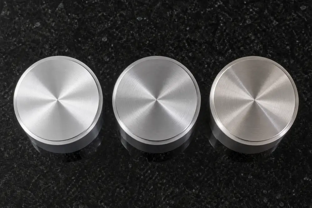
For structural sliding components, hard anodizing 6061 aluminum represents the premier industrial standard. Al6061 contains magnesium and silicon that form clean magnesium-silicide precipitates, allowing uniform hexagonal oxide cells to develop. Applying aluminum CNC machining design guidelines to 6061-T6 produces hardness readings reliably between 900 and 1000 HV. Using the T651 temper eliminates internal stresses, preventing component distortion during processing.
Al7075-T6: High Yield Strength with Dielectric Voltage Limits
Aerospace-grade 7075-T6 anodizes well, but its 5.1 to 6.1 percent zinc content increases electrical resistance across the barrier layer. This demands higher operating voltages, producing wider pores and a slightly lower micro-hardness of 750 to 850 HV. Natural, un-dyed coatings on 7075 appear olive-drab or bronze. While 7075 provides superior core strength, 6061 is preferred for sliding wear resistance.
Al2024-T3: Copper Dissolution, Burning and Pulse Rectification
Alloys containing more than 2.0 percent copper, such as 2024, introduce severe processing risks. Copper phases dissolve into the acid rather than forming stable oxides, triggering localized micro-arcing that melts component edges. Successfully hardcoating 2024 requires reducing tank temperatures below zero degrees Celsius and utilizing specialized pulsed rectifiers. Even when processed properly, 2024 achieves hardness values of only 550 to 650 HV and rarely supports coatings thicker than 35 microns.
Cast Aluminum Alloys (A380, A356): Silicon Inclusions and Spalling
Specifying functional hardcoat on high-silicon die-castings is a critical design mistake. Die-cast alloys contain 7.5 to 9.5 percent silicon, an element that does not convert to aluminum oxide. Instead, raw silicon inclusions become trapped in the film, creating a fragile, non-adherent layer prone to spalling. Review our technical guide on machining and surface treating cast aluminum to evaluate proper conversion alternatives.
|
Alloy Material Grade |
Principal Alloying Elements |
Practical Thickness Limit |
Achievable Micro-Hardness |
Process Yield / Rejection Risk |
|
Al6061-T6 |
1.0% Mg, 0.6% Si |
75 microns (0.0030 in) |
900 to 1050 HV |
High Yield / Low Risk |
|
Al7075-T6 |
5.6% Zn, 2.5% Mg |
60 microns (0.0024 in) |
750 to 850 HV |
High Yield / Moderate Risk |
|
Al2024-T3 |
4.4% Cu, 1.5% Mg |
35 microns (0.0014 in) |
550 to 650 HV |
Moderate Yield / High Burning Risk |
|
Al5052-H32 |
2.5% Mg, 0.25% Cr |
65 microns (0.0025 in) |
800 to 900 HV |
High Yield / Low Risk |
|
A380 (Cast) |
8.5% Si, 3.5% Cu |
20 microns (0.0008 in) |
350 to 500 HV |
Low Yield / Severe Flaking Risk |
Precision Masking Methods and the Chemical Stripping Scrap Trap
On standard decorative anodizing lines, components with visual imperfections can be stripped in hot caustic solutions and re-coated with minimal base metal loss. Applying this practice to Type III hardcoat destroys precision parts.
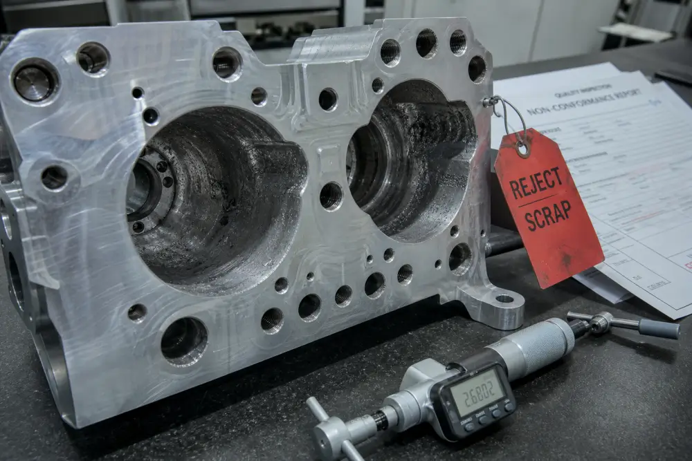
Why Chemical Stripping Ruin Base Metal Tolerances
Because hardcoat forms a dense ceramic matrix, stripping chemicals require 30 to 60 minutes to dissolve a 50-micron coating. The acid or caustic solution penetrates the vertical pores and micro-cracks, attacking the raw aluminum substrate beneath while the surface ceramic is still dissolving.
By the time the hardcoat is removed, the chemistry has etched away 25 to 50 microns of base metal. Bearing bores emerge oversized, thread crests are dissolved, and ground faces lose planarity. At Dazao, hard-anodized parts that fail dimensional checks cannot be stripped; they are scrapped.
Silicone Plugs, Lacquers and Edge Capillary Bleed Prevention
When specific features must remain raw metal, masking materials must endure high voltages and agitated acid:
· Molded Silicone Plugs: Required for tapped holes to prevent acid ingress. Plugs must compress firmly against lead-in chamfers.
· Precision Polyimide Tape: Used for flat electrical grounding pads. Poor tape adhesion causes acid to creep via capillary action, etching feathered reject zones.
· Chemical Stop-Off Lacquers: Applied manually on complex profiles and cured thermally.
Masking always creates a raised transition lip of 25 microns at the boundary where the coating ends, which can obstruct sliding mechanisms.
Post-Anodize Diamond Machining (PCD) vs Complex Masking
Given the labor costs and leakage risks of masking, post-anodize machining provides a superior alternative for tight tolerances. Dazao frequently coats components entirely without masking, returning them to high-precision equipment running precision CNC machining services at Dazao.
Operators cut through the 1000 HV ceramic layer on designated bearing fits using Polycrystalline Diamond (PCD) or Cubic Boron Nitride (CBN) inserts. This yields precise journal locations, eliminates masking labor, and ensures surface finishes down to Ra 0.2 microns.
Engineering Drawing Callouts: MIL-A-8625 Type III Standards and Tolerances
Ambiguous technical drawings remain a primary cause of production delays and component rejections. Simply noting hard anodize black on a print leaves critical engineering requirements undefined.
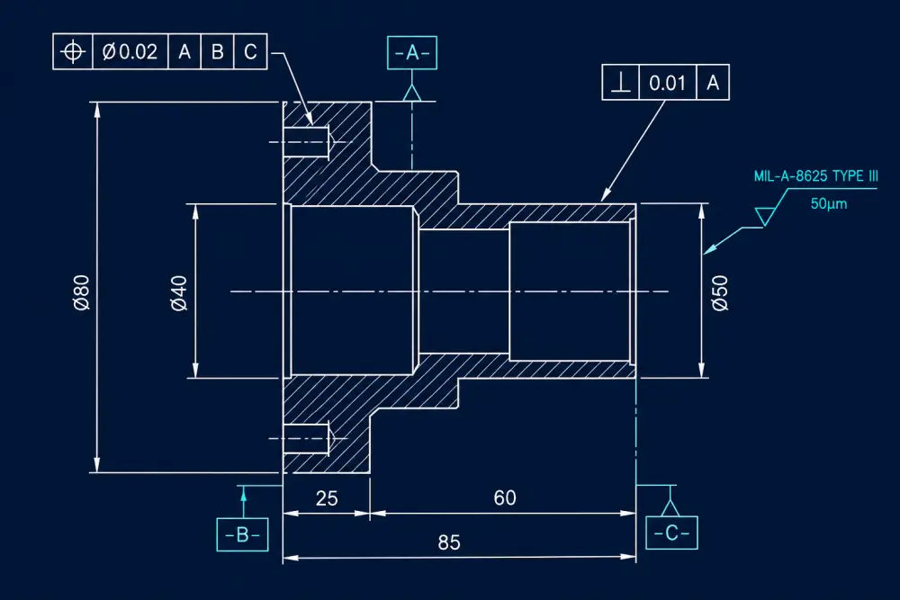
MIL-A-8625 Type III Class 1 vs Class 2 Specification Clauses
Drawings should reference established industry standards:
· MIL-A-8625, Type III, Class 1: Non-dyed, displaying natural shades from charcoal gray to bronze.
· MIL-A-8625, Type III, Class 2: Dyed, almost exclusively black. Dark natural oxide prevents bright colors.
· AMS 2469: Aerospace specification governing hard anodic coatings on aluminum alloys.
· ISO 10074: International standard defining hard anodizing parameters.
Establishing an unambiguous hard anodizing drawing callout protects project timelines and eliminates supplier misunderstandings. A correct note structure must state: Anodize per MIL-A-8625F, Type III, Class 1, coating thickness 50 microns plus or minus 10 microns, with all dimensional limits applying after processing and unsealed for sliding wear service.
Defining Pre-Plate vs Post-Plate Dimensions Legally
Machine shops evaluate engineering drawings strictly by their explicit notes. Prints must clearly state: ALL DIMENSIONAL TOLERANCES APPLY AFTER ANODIZING.
With this directive, programmers apply negative offsets to outside diameters and expand bore dimensions in early operations. If dimensions apply prior to treatment, the note must state: Dimensions apply prior to surface treatment.
Predicting Surface Roughness (Ra) Degradation
Hardcoating alters microscopic surface textures. The energetic conversion reaction degrades fine finishes, increasing roughness values by 1.5 to 2.5 times. Refer to our reference guide for understanding the CNC surface roughness chart and Ra limits.
A ground finish of Ra 0.4 microns will shift toward Ra 0.8 to 1.0 microns post-coating. If an application demands an Ra value under 0.2 microns for dynamic seals, the processing plan must include post-anodize diamond micro-lapping or honing.
Hard Anodizing Cost Drivers and Dazao DFM Sourcing Checklist
Accurately calculating hard anodizing cost requires assessing variables well beyond part surface area. The process operates under demanding electrochemical regimes, and specific design features drive processing expenses upward. Review our detailed breakdown of aluminum CNC machining cost drivers to understand total part economics.
Power Density, Chilling and Masking Labor Cost Breakdown
· Electrical Power and Cooling: Operating high-current baths at sub-zero temperatures requires substantial industrial chiller refrigeration to counter exothermic reaction heat.
· Manual Masking Labor: Installing plugs, trimming tapes, and painting stop-off lacquers can account for more than 50 percent of the total finishing invoice.
· Dedicated Titanium Fixtures: Carrying hundreds of amperes into workpieces requires heavy-duty titanium clamps.
Clamping Footprints and Titanium Rack Witness Marks
Unlike decorative parts wired onto light racks, Type III parts require heavy mechanical clamping. These contact points shield the underlying aluminum, leaving bare witness marks.
Procurement teams must identify non-critical faces where clamping marks are acceptable. Prohibiting rack marks entirely forces the use of expanding internal threaded collets, driving up fixture and handling costs.
Dazao Pre-Production DFM Verification Checklist
Before releasing production drawings, verify these five engineering checks:
1. Is Type III genuinely required, or does 15-micron Type II provide sufficient corrosion resistance at lower cost?
2. Are all external edges designed with at least an R0.5 mm radius to prevent corner dog-boning?
3. Have deep blind bores been evaluated for internal auxiliary cathode tooling or secondary reaming?
4. Has CAD modeling accounted for 50 percent outward dimensional growth across critical features?
5. Have you evaluated post-anodize diamond machining as a cost-effective alternative to complex manual masking?
Strategic Implementation: Managing Electrochemical Growth in Precision CNC Machining
Type III hard anodizing bridges the mechanical performance gap between lightweight aluminum alloys and heavy case-hardened steels. Approaching this process as an integrated metallurgical transformation rather than a cosmetic after-treatment prevents the costly fit-up and sliding failures that disrupt precision assembly lines.
Success requires proactive engineering: calculating dimensional changes during early modeling, choosing optimal alloys like 6061-T6, avoiding incompatible counterfaces like raw stainless steel, adding generous corner radii, and issuing precise technical drawing callouts. Incorporating these manufacturing controls protects project timelines and ensures reliable field performance under severe operating conditions.

FAQs
01.Why do internal threads seize after Type III hard anodizing?
02.Can an out-of-tolerance hard anodized part be chemically stripped and redone?
03.Why do non-dyed Type III hardcoat parts show different colors across batches?
04.How do you prevent ceramic spalling during dowel pin press-fitting?
05.Why does black Type III hardcoat sometimes fade to a purple hue?
06.Why do unlubricated stainless steel bolts gall inside hard anodized threads?