


Specifying surface roughness is a functional engineering calculation, not a cosmetic preference. Over-specifying finishes inflates cycle times and production expenses exponentially: reducing roughness from Ra 0.8 vs Ra 1.6 surface finish down to Ra 0.4 µm can triple cycle times and double total component costs without providing functional value. This technical manual details the mathematical boundaries of Ra vs Rz metrics, defines process limits across 3-axis, 5-axis, and grinding setups, and outlines the micro-tribological requirements for dynamic seals, bearing seats, and structural interfaces based on empirical production data from the Dazao machining facility.
On standard manufacturing drawings, the surface finish block is frequently treated as an afterthought. Designers often assign a blanket Ra 0.4 µm (16 µin) or Ra 0.8 µm (32 µin) callout across an entire part title block to guarantee quality. In high-precision CNC machining, this practice creates an immediate cost multiplier. When evaluating overall production budgets, understanding the baseline aluminum CNC machining cost factors helps avoid arbitrary over-specification on non-mating faces.
At the Dazao manufacturing plant, an engineering review of an Al6061-T6 fluid distribution manifold designed for semiconductor cooling equipment highlighted this exact issue. The original CAD drawing specified an all-over surface texture of Ra 0.4 µm. To achieve this requirement across deep internal cavities, pockets, and external mounting tabs, the initial production routing mandated high-feed roughing, secondary semi-finishing with small step-overs, fine finish milling at reduced feeds, and manual bench polishing on non-mating external surfaces. The resulting unit price sat at $130 per component, accompanied by an extended 22-minute machining cycle.
Dazao initiated a Design for Manufacturability (DFM) review with the client mechanical engineering team. Functional segmentation revealed that only two internal port faces interfaced with fluorocarbon O-rings, and only one planar face mounted to a thermoelectric cooler. The external flanges, mounting brackets, and clearance pockets performed purely structural duties.
Dazao revised the drawing:
· External non-functional surfaces were relaxed to Ra 3.2 µm (125 µin), cut in a single finishing pass with an 8 mm corner-radius end mill.
· The thermal contact face was assigned Ra 0.8 µm (32 µin) via face milling.
· The static sealing counterbores were held to Ra 1.6 µm (63 µin) with a circular interpolation toolpath.
This targeted adjustment dropped cycle times from 22 minutes to 8.5 minutes. By eliminating unnecessary secondary benching, parts moved directly from the machine without the added lead times documented in our deburring aluminum parts cost guide. Unit manufacturing cost dropped from $130 to $45, scrap rates dropped to zero, and lead times were compressed by three weeks. Achieving optimal CNC surface roughness requires matching micro-topographical geometry to mechanical duty. Understanding the physics of contact surfaces prevents severe financial waste in precision part manufacturing.
Micro-Topography Demystified: Ra vs Rz surface roughness and Contact Mechanics
Surface roughness quantifies the vertical deviations of a real mechanical surface from its ideal geometric form. When assessing Ra vs Rz surface roughness, evaluating how these two profiles are calculated reveals why relying exclusively on Ra compromises high-load assemblies.
Statistical Averaging Flaws of the Ra Parameter in Load-Bearing Assemblies
Roughness Average (Ra) is the arithmetic mean of absolute values of the profile height deviations recorded along an evaluation length, measured from the mean graphical centerline.
Because Ra integrates and averages all micro-peaks and micro-valleys across the sampling stroke, it is an integrated statistical metric. This math creates an engineering hazard: two surfaces with completely different micro-topographies can yield the exact same Ra reading.
A surface featuring a flat bearing plateau interrupted by three deep machining gouges can register an identical Ra 0.8 µm value to a uniform, symmetrical sine-wave surface composed of sharp peaks and shallow valleys. If that surface operates as a high-pressure hydraulic face, the deep gouges in the first profile will act as direct leak paths. Conversely, if the second surface supports a heavy bearing load, the sharp peaks will encounter intense localized contact stress, deform plastically during initial startup, and shed metal debris directly into the lubricant system.
Peak-to-Valley Realities: Why Rz Defines Fatigue and Dynamic Seal Longevity
Rz measures the average maximum peak-to-valley height calculated across several consecutive individual sampling lengths (traditionally five sampling cut-offs under ISO 4287 and ASME B46.1).
By evaluating the distance between the highest peak and the deepest valley within each cut-off zone:
· Extreme peaks that cause galling, interference fit seizure, and high localized friction are highlighted.
· Deep valleys that create leakage paths, fatigue notch concentrations, and fluid bypass channels are captured.
For components exposed to cyclic mechanical fatigue, such as aerospace actuator rods or automotive powertrain splines, an isolated deep scratch acts as a localized stress riser that initiates micro-cracks. Ra completely masks this defect, whereas Rz flags it immediately.

The Material Ratio Curve (Abbott-Firestone): Contact Area vs Lubricant Void Volume
A major gap in basic surface roughness discussions is the failure to consider the Material Ratio Curve, historically known as the Abbott-Firestone curve. This metric records the ratio of contact bearing area to non-contact void volume as a function of profile depth.
When establishing surface roughness values for CNC machining, two surfaces cut to identical Ra 0.8 µm tolerances typically present completely divergent functional bearing profiles:
· Asperity Peak Profile: Generated by worn cutting tools, excessive feed rates, or unstable chip formation. The surface contact area at twenty percent profile depth is under fifteen percent. When clamping bolts are torqued down or bearing press-fits are installed against this profile, the microscopic tips immediately crush under plastic deformation. The joint loses bolt preload tension, causing subsequent dimensional shift and joint looseness.
· Plateau-Honed Profile: Generated through rigid tooling, optimized tool nose radii, and controlled semi-finish and finish cutting paths. The plateaus provide an immediate sixty to seventy percent material contact area at shallow depths, while the residual micro-valleys act as fluid reservoirs. The assembly maintains its initial preload torque indefinitely, resists early adhesive scuffing, and provides stable hydrodynamic film support.
CNC surface finish chart and Physical Machining Constraints
The attainable surface profile is fundamentally governed by the physics of metal removal: the geometry of the tool cutting edge, feed rates, structural rigidity of the machine-tool-workpiece loop, and cutting fluid delivery. Achieving repeatable micro-finishes demands rigid machine centers such as those deployed across Dazao precision custom CNC machining services.
Real-World Machining Capabilities Across Milling, Turning, and Grinding
The following CNC surface finish chart identifies the standard operational limits, achievable roughness brackets, and comparative cost multipliers across volume manufacturing operations at Dazao.
|
Machining Process |
Standard Production Range (Ra, µm) |
Precision Limit Range (Ra, µm) |
Typical Rz Range (µm) |
Dimensional Tolerance Capability (mm) |
Cost Multiplier Index |
|
Rough CNC Milling / Turning |
Ra 3.2 - 6.3 |
Ra 2.5 |
Rz 12.5 - 25.0 |
±0.10 to ±0.20 |
1.0x (Baseline) |
|
Standard 3-Axis CNC Milling |
Ra 1.6 - 3.2 |
Ra 1.2 |
Rz 6.3 - 12.5 |
±0.025 to ±0.050 |
1.4x - 1.8x |
|
Precision 5-Axis CNC Milling |
Ra 0.8 - 1.6 |
Ra 0.4 |
Rz 3.2 - 6.3 |
±0.010 to ±0.025 |
2.2x - 3.0x |
|
Precision CNC Turning |
Ra 0.8 - 1.6 |
Ra 0.4 |
Rz 3.2 - 6.3 |
±0.008 to ±0.015 |
1.5x - 2.0x |
|
Cylindrical / Surface Grinding |
Ra 0.2 - 0.8 |
Ra 0.1 |
Rz 0.8 - 3.2 |
±0.002 to ±0.005 |
3.5x - 5.0x |
|
Lapping / Diamond Polishing |
Ra 0.025 - 0.1 |
Ra 0.012 |
Rz 0.1 - 0.5 |
±0.001 to ±0.002 |
8.0x - 15.0x+ |
Theoretical Cusp Height Mechanics vs Machine Tool Physical Boundaries
In a turning or face-milling operation free of vibration, mechanical runout, and thermal growth, surface roughness is strictly dictated by cutting tool nose radius and feed rate. As the cutting tool advances across the revolving or stationary workpiece, the spherical nose profile traces a series of overlapping circular arcs. The material remaining between two consecutive passes forms a residual cusp or scalloped ridge.
The theoretical peak-to-valley height of this cusp depends directly on the square of the feed per revolution (or feed per tooth in milling) divided by eight times the tool corner radius. To halve the theoretical cusp height, an operator cannot simply double the spindle speed. Spindle velocity does not alter the geometric footprint of the tool path. The feed rate must be reduced, or the tool nose radius must be expanded.
However, both adjustments hit physical barriers on the shop floor:
· The Minimum Chip Thickness Effect: If the feed per tooth is reduced below the cutting edge honing radius (typically 5 to 15 µm on coated carbide inserts), the tool ceases to shear metal cleanly. Instead, the tool edge rubs and burnishes the stock, plowing the alloy, inducing severe compressive residual stresses, generating extreme heat, and deteriorating the actual finish from a theoretical Ra 0.4 down to an unstable, torn Ra 1.6.
· Chatter and Tool Deflection: Increasing the tool nose radius from 0.4 mm to 1.6 mm expands the tool-to-workpiece contact length. This dramatically increases radial cutting forces. On slender parts, long-overhang boring bars, or thin-walled components, these radial loads induce dynamic chatter, producing cyclical wavy marks that ruin the surface profile.

Production Floor Disruptions: Chatter, Runout, and Minimum Chip Thickness
When tuning machine tools at Dazao, machinists actively monitor three primary disruptions that prevent parts from matching theoretical surface finish charts:
1. Chip Recutting and Entanglement: Long, stringy swarf produced during ductile metal operations that fails to break against the insert geometry wraps around the tool shank. These trapped chips drag across the freshly cut surface, engraving chaotic scratches that spike Rz readings without warning.
2. Dynamic Harmonic Vibration (Chatter): Mismatches between spindle speeds and machine structural natural frequencies generate regenerative chatter. This leaves a distinctive pattern of faceted reflections and periodic undulating waves across the surface.
3. Tool Runout and Flank Edge Micro-Chipping: A tool holder displaying just 5 µm of dynamic radial runout causes a single flute on a four-flute end mill to carry the entire finishing load while the remaining flutes cut air. Even microscopic flank degradation causes immediate surface tearing, a mechanism detailed in our analysis of CNC tool wear types and causes.
Application-Driven Selection: Ra 0.8 vs Ra 1.6 surface finish for Critical Interfaces
Selecting between Ra 0.8 and Ra 1.6 requires analyzing the operational mode of the mating components rather than defaulting to the tighter number.
Structural Mating Surfaces and Locating Bores (Ra 1.6 to Ra 3.2 µm)
For rigid structural mounts, gearbox outer covers, motor adapter plates, and bracket interfaces, specifying Ra 1.6 µm or Ra 3.2 µm is standard practice. These surfaces depend on bolt clamp loads to generate frictional shear resistance.
Extremely smooth surfaces (under Ra 0.8 µm) lower the static friction coefficient across dry unlubricated joints. This increases reliance on dowel pins to resist joint slipping under transverse shear loads. Furthermore, a surface prepared to Ra 3.2 µm provides superior mechanical interlocking tooth for structural adhesives, primers, and powder coatings compared to a burnished, low-roughness surface.
Interference Fits and Precision Bearing Journals (Ra 0.8 µm)
Inner and outer bearing rings demand an interface engineered to Ra 0.8 µm (32 µin) or finer, controlled alongside strict roundness tolerances (typically within 0.005 mm). Surface micro-finish works in direct tandem with geometric limits, as established in our guide to CNC tolerance design and GD&T cost optimization.
When press-fitting an anti-friction ball bearing onto an arbor shaft, the interface relies on calculated micro-interference (such as an ISO k5 or m5 tolerance class). If the shaft is cut too coarse (Ra 1.6 to 3.2 µm), the microscopic peak asperities will shear off or crush flat during press-mounting. This mechanical flattening reduces the intended interference fit, leaving the inner ring under-clamped. Under heavy cyclic torque reversals, the ring will walk, creep, and frett against the shaft seat, culminating in catastrophic bearing seizure.
Static Gasket and O-Ring Grooves: Preventing Radial Leak Paths
When selecting the proper surface roughness for sealing surfaces, design requirements split sharply between static elastomeric seals (such as O-rings) and dynamic reciprocating or rotating seals.
For static elastomeric seals operating up to 10 MPa (1450 psi), a surface finish between Ra 0.8 µm and Ra 1.6 µm represents the operational sweet spot:
· An elastomer must conform under initial compression into the micro-cavities of the machined metal. If the face is rougher than Ra 3.2 µm, the rubber cannot deform fully into the deep valley troughs, permitting pressurized gas or low-viscosity hydraulic oil to track across the seal.
· Toolpath Lay Orientation: The direction of the surface lay relative to the contained fluid pressure is critical. Face-milling across an O-ring groove face leaves radial cutter arc lines that bridge the high-pressure side directly to the ambient atmosphere. These micro-arcs serve as open fluid escape channels. Static sealing grooves must always display a concentric, circular, or multi-directional cross-hatched lay orientation relative to the perimeter of the seal.
The Hydrodynamic Lubrication Failure Mode in Dynamic Reciprocating Seals
A costly error observed in precision manufacturing is mirror-polishing a reciprocating shaft or hydraulic piston rod down to Ra 0.05 µm (2 µin) under the assumption that smoother surfaces always extend seal longevity.
Dazao reviewed a batch of hydraulic actuator cylinder assemblies returned from service due to rapid fluid leakage and damaged nitrile U-cup seals after fewer than 300 cycles. The customer engineering team had polished the chrome-plated reciprocating rods down to a mirror finish of Ra 0.03 µm.
The failure mode was lubrication starvation:
· Dynamic reciprocating seals require the presence of a microscopic hydrodynamic fluid film measuring between 0.1 and 0.5 µm thick between the sliding elastomer lip and the moving steel rod.
· This microscopic oil film is sustained by the shallow micro-valleys of the machined metal profile, which act as micro-hydrodynamic reservoirs.
· On a surface polished to Ra 0.03 µm, these micro-reservoirs are wiped clean. The elastomeric seal makes direct, unlubricated contact with the dry metal face. Friction temperatures spike rapidly, the rubber vulcanizes, degrades, and embrittles, and the seal lip shreds, inducing immediate dynamic fluid bypass.
For dynamic hydraulic rod assemblies, the correct engineering specification is a cross-hatched, plateau-finished surface held between Ra 0.15 µm and Ra 0.30 µm (6 to 12 µin), combined with an Rz limit under 1.5 µm. This micro-geometry preserves a stable hydrodynamic boundary layer while preventing peak asperities from penetrating the elastomeric seal lip.
Aluminum Milling Challenges: surface roughness aluminum and Post-Anodizing Inversion
Achieving a stable surface roughness aluminum profile requires controlling material ductility and thermal behavior during high-speed shear. Wrought alloys such as Al6061-T6 and Al7075-T651 exhibit high thermal expansion coefficients and a strong chemical affinity for standard cutting tool binders. Maintaining stable shear without tearing requires optimal chip thinning strategies covered in our high-speed machining aluminum guide.
Ductile Shear Mechanics: Preventing Built-Up Edge on 6061 and 7075 Alloys
When cutting speeds or chip evacuation rates fluctuate, aluminum micro-welds to the rake face of carbide inserts, forming a Built-Up Edge (BUE). Once a BUE develops, high frictional heat welds chip fragments directly onto the tool face, fundamentally changing the cutting edge geometry. The effective rake angle shifts unpredictably, transforming sharp shearing action into continuous burnishing and plowing.
As the cutting pressure fluctuates, the hardened BUE breaks away periodically, tearing parent material straight from the finished workpiece and leaving micro-voids behind. Through this cycle, a surface intended for Ra 0.8 µm degrades rapidly into a torn, scuffed profile exceeding Ra 3.2 µm.
To preserve micro-inch surface integrity in aluminum milling, Dazao mandates high-pressure through-spindle coolant (minimum 70 bar or 1000 psi) to evacuate swarf before recutting can occur. Furthermore, finishing passes utilize balanced tool holders paired with Polycrystalline Diamond (PCD) or Diamond-Like Carbon (DLC) coated end mills. Choosing dedicated geometries prevents material pickup, following principles from our end mill selection guide.
The Roughness Inversion Effect in Chemical Etching and Hardcoat Anodizing
A frequent assumption in mechanical design is that subsequent surface finishing will smooth out tool marks. Production data reveals that surface roughness after anodizing frequently degrades rather than improves. Chemical pretreatments interact directly with machined grain boundaries, a factor explored in our aluminum surface finishing guide.
During standard anodizing pretreatments, parts undergo alkaline etching in a heated sodium hydroxide bath to strip natural oxidation. This chemical attack preferentially corrodes grain boundary intermetallics (such as magnesium-silicide phases in 6000-series alloys).
If the base surface contains cold-worked residual shear stresses or uneven micro-scallops from rapid finish milling:
1. The alkaline bath etches along those directional stress lines, widening micro-crevices.
2. A freshly machined surface measuring Ra 0.4 µm can degrade to Ra 0.8 µm to Ra 1.2 µm after basic chemical etching.
3. In Type III Hardcoat Anodizing (MIL-A-8625), where an anodic oxide layer of 40 µm to 50 µm is grown under high current densities and sub-zero acid baths, the oxide layer develops as an array of columnar hexagonal cells. Because these columnar structures grow perpendicular to the microscopic peaks and valleys of the substrate, the crystalline growth exaggerates the underlying topography.
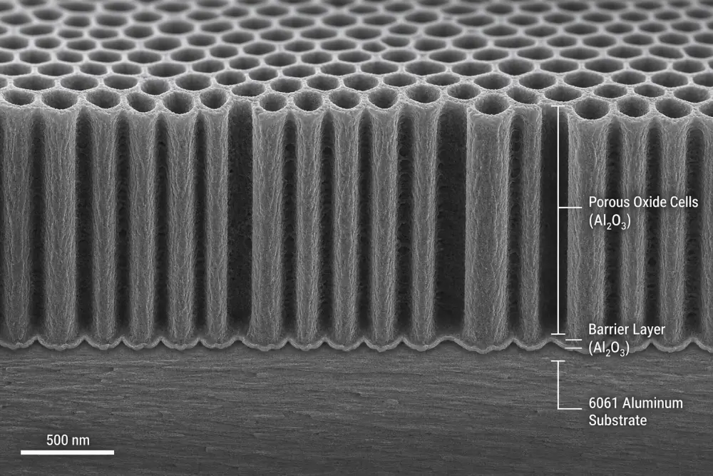
Dazao resolved a critical field failure on a batch of drone camera gimbal pivot shafts where a bearing seat called out Ra 0.4 µm and an ISO h6 diameter tolerance. The components were machined to specification in the green state. After 50 µm hardcoat anodizing, the surface roughness degraded to Ra 1.1 µm, and the micro-scale volumetric expansion choked the bearing journals, causing bearing bind during final assembly.
To prevent post-treatment dimensional failure:
· Drawings must explicitly specify whether surface roughness tolerances apply before anodizing or after final coating.
· If a post-anodize finish of Ra 0.4 µm is mandatory, the green CNC substrate must be precision-machined to Ra 0.2 µm or polished prior to electrochemical processing to account for post-treatment growth.
Blueprint Callout Standards: surface roughness symbols on engineering drawings
Ambiguous drawing callouts remain a major cause of manufacturing disputes and unintended cost overruns. Correctly placing surface roughness symbols on engineering drawings requires strict adherence to international standards (ISO 1302 and ASME Y14.36M).
Anatomy of ISO 1302 and ASME Y14.36M Surface Texture Designations
A standardized surface texture callout uses a basic checkmark outline with specific modifier locations:
· The Checkmark Base: A basic open checkmark indicates a surface where material removal is optional. A checkmark enclosed with a horizontal crossbar at the bottom mandates material removal by machining. A checkmark containing a circle inside the apex specifies that material removal is strictly prohibited, which is standard for cast surfaces, forging skins, or sheet stock.
· Upper Parameter Limit: Positioned directly above the horizontal extension line, this designates the maximum allowable roughness threshold (such as Ra 0.8). When dual limits are specified to establish an oil retention band, the upper limit is placed directly over the lower limit.
· Machining Method: Placed along the upper horizontal line, this text defines the required manufacturing process (such as Ground, Turned, or Milled) only when a specific method is functionally mandatory.
· Surface Lay Direction: Positioned below the horizontal extension bar, this symbol dictates the required orientation of tool marks relative to the drawing view.
· Machining Allowance: Positioned to the left of the checkmark apex, this numeric value defines the minimum required stock removal allowance in millimeters.
Specifying Surface Lay Directions for Pressurized Boundaries
When managing sealing surfaces, the microscopic direction of the tool marks controls fluid containment integrity:
|
Lay Symbol |
Texture Direction Relative to Drawing Projection |
Functional Application |
|
= |
Parallel to the plane of projection |
Low-wear linear guides and sliding gibs |
|
⊥ |
Perpendicular to the plane of projection |
Brake friction faces and mechanical clamp pads |
|
X |
Angularly crossed in two oblique directions |
Honed cylinder liners for hydrodynamic oil retention |
|
M |
Multi-directional, non-directional, or random |
High-pressure static gasket and O-ring mating flanges |
|
C |
Circular and roughly concentric to part center |
Turned face-seal O-ring grooves |
|
R |
Radial relative to the center of the surface |
Flat thrust bearing runners |
Eliminating Drawing Ambiguity and Title-Block Over-Specification
· Blanket Title-Block Requirements: Specifying a global title-block note such as all machined surfaces to be Ra 0.8 µm unless otherwise noted forces the machine shop to run fine finishing passes on non-critical clearance faces, tapped hole internal minor diameters, and external edge chamfers. Conducting direct engineering DFM design reviews prior to quote release resolves these blanket liabilities.
· The Deep Cavity Accessibility Blind Spot: Calling out an Ra 0.4 µm finish at the bottom floor of an internal pocket with a length-to-diameter tool aspect ratio exceeding 6 to 1 requires non-standard long-reach tooling. At these tool extensions, deflection and harmonic vibration make fine finishes difficult to achieve without specialized electrical discharge machining (EDM) or custom abrasive flow machining.
Metrology Verification: how to measure surface roughness Without Quality Disputes
Verifying micro-topography on the shop floor requires a firm understanding of how to measure surface roughness using stylus profilometers and optical metrology systems.
Stylus Profilometry Mechanics and Diamond Tip Geometry Filtering
A contact stylus instrument draws a diamond-tipped probe (standard tip radius of 2 µm or 5 µm with a 60-degree or 90-degree cone angle) across the component face at a controlled traverse speed. A mechanical-inductive or optical sensor tracks the vertical displacement of the diamond tip relative to an internal reference datum or reference skid. Rigorous quality operations rely on certified in-house precision metrology and CMM inspection capabilities to guarantee correlation.
· Tip Radius Filtering: A 5 µm radius stylus cannot physically penetrate narrow micro-valleys narrower than 5 µm. It rides across the valley shoulders, mechanically filtering out the true valley depth. For precision ground or polished surfaces, a 2 µm stylus tip is required to avoid under-reporting peak-to-valley distances.
· Non-Contact Optical Metrology Limits: White-light interferometry and confocal laser scanning provide high-speed three-dimensional scans without surface contact. However, on highly reflective aluminum or curved surfaces with steep local slopes, optical scatter and specular reflections can generate false height spikes, yielding inflated Ra and Rz metrics. For contractual acceptance at Dazao, contact diamond stylus tracing remains the definitive baseline.

The Cut-Off Wavelength Conflict: Aligning Sampling Rules Under ISO 4288
The most common quality dispute between design buyers and precision manufacturing plants involves the omission of the cut-off wavelength parameter.
A profilometer does not measure a single continuous line and convert it directly into Ra. It passes the raw profile data through a mathematical Gaussian filter that separates high-frequency micro-roughness from low-frequency surface waviness and form errors. The cut-off wavelength defines the filter boundary: high frequencies shorter than the cut-off length are computed as surface roughness, while longer low-frequency waves are filtered out as waviness.
At the Dazao inspection laboratory, a batch of optical mounting plates was flagged for rejection by an overseas customer incoming quality team. The drawing called out Ra 0.8 µm without stating a cut-off length or filtering standard.
· The customer receiving inspector set the profilometer to a default cut-off wavelength of 2.5 mm with a total evaluation length of 12.5 mm. Under this broad window, the instrument captured the low-frequency machine tool pitch variation across the large plate and combined it with the micro-profile, yielding a failing reading of Ra 1.15 µm.
· Dazao verified the parts per ISO 4288, which governs default measurement rules. Under ISO 4288, non-periodic surfaces with an expected Ra between 0.1 µm and 2.0 µm require a cut-off wavelength of 0.8 mm and an evaluation length of 4.0 mm.
· When re-inspected under the standard 0.8 mm cut-off setting, the low-frequency waviness was isolated, and the actual micro-roughness registered at Ra 0.65 µm, well within the engineering tolerance limit.
To prevent costly quality disputes, mechanical drawings and inspection agreements must explicitly state the filter parameters, defining both the target Ra threshold and the 0.8 mm cut-off length.
Manufacturing Economics: Quantifying CNC surface finish cost Multipliers
The relationship between surface finish requirements and manufacturing expense is non-linear. Tighter finishes require exponential cycle-time expansions, specialized tooling setups, secondary processing, and lower yields, driving up total CNC surface finish cost.
Cycle Time and Secondary Operation Cost Progression Across Ra Tiers
Moving from a standard commercial finish down to an optical or fluid-tight profile transforms machining economics:
· From Ra 3.2 µm to Ra 1.6 µm: Step-over distances in ball-nose milling are halved. Machine axis feeds are throttled down by thirty to fifty percent on finishing passes. Machining cycle time increases by forty to sixty percent.
· From Ra 1.6 µm to Ra 0.8 µm: Standard tool paths must be split into dedicated semi-finishing and finishing sequences to minimize tool deflection. Tool replacement intervals tighten to prevent micro-chipped edges from degrading the finish. Costs rise by approximately two to two-and-a-half times over baseline.
· From Ra 0.8 µm to Ra 0.2 µm: Standard 3-axis or 5-axis CNC milling cannot consistently hit this threshold in production volumes. The process requires specialized cylindrical or surface grinding, requiring secondary part setups, custom locating fixtures, stress-relief heat treatment cycles to prevent grinding warp, and coordinate checking via CMM. Cost multiplier reaches three-and-a-half to five times baseline.
· Sub-Ra 0.1 µm (Super-Finishing / Polishing): Grinding must be followed by manual diamond lapping, abrasive flow machining, or vibratory barrel polishing. Scrap risks compound due to manual handling errors. Cost multiplier exceeds eight to fifteen times baseline.
The following cost model reflects internal production data at Dazao for facing an Al6061-T6 structural interface measuring 100 mm by 100 mm:
|
Target Surface Finish (Ra) |
Required Manufacturing Process Sequence |
Finishing Pass Feed Rate (mm/min) |
Cycle Time per Face (Minutes) |
Tooling & Consumables Cost per Unit |
Relative Unit Cost Index |
|
Ra 6.3 µm (250 µin) |
Single-pass rough face mill |
2200 |
0.8 min |
$0.40 |
1.0x |
|
Ra 3.2 µm (125 µin) |
Roughing + single finishing pass |
1600 |
1.4 min |
$0.85 |
1.25x |
|
Ra 1.6 µm (63 µin) |
Roughing + semi-finish + finish pass |
900 |
2.8 min |
$1.60 |
1.70x |
|
Ra 0.8 µm (32 µin) |
Dynamic rough + fine finish (PCD tool) |
450 |
5.5 min |
$3.20 |
2.45x |
|
Ra 0.2 µm (8 µin) |
CNC rough mill + surface grind setup |
N/A (Grinding pass) |
14.0 min |
$8.50 |
4.80x |
|
Ra 0.05 µm (2 µin) |
Mill + grind + manual diamond lapping |
N/A (Manual process) |
35.0 min |
$22.00 |
11.50x |
DFM Protocol: Tiered Surface Finish Callouts for 30%+ Cost Reduction
Designers can balance cycle times and cosmetic value by consulting our core aluminum CNC machining guide. Implementing a tiered surface finish methodology yields substantial savings:
1. Tier 1 (Critical Interfaces): Restrict Ra 0.8 µm or Rz 3.2 µm solely to precision bearing fits, dynamic seal journals, and high-frequency thermal transfer interfaces.
2. Tier 2 (Static Fit Surfaces): Assign Ra 1.6 µm to Ra 3.2 µm to O-ring glands, bolt clamping faces, and dowel locating blocks.
3. Tier 3 (Clearance Enclosures): Relax internal pocket floors, non-mating cosmetic walls, and weight-relief cutouts to Ra 6.3 µm.
This tiered discipline eliminates unnecessary fine-pitch passes, reducing machining cycle times by thirty to forty-five percent while preserving all core mechanical functions.
Engineering Review and Procurement Quality Alignment Protocols
Before releasing CAD models and production prints to quotation, run this eight-point audit developed on the Dazao manufacturing floor to optimize manufacturing efficiency and avoid costs linked to over-specification.
5-Point DFM Design Verification Before Drawing Release
· Eliminate Global Title-Block Defaults: Ensure the drawing title block does not enforce an arbitrary blanket specification (such as Ra 0.8 µm) on unmachined faces, clearance bores, tapped threads, and non-contact relief cuts.
· Separate Static vs Dynamic Sealing Zones: Limit static O-ring grooves to Ra 0.8 to Ra 1.6 µm with concentric circular or multi-directional lay patterns. Do not mirror-polish dynamic reciprocating seals below Ra 0.15 µm to avoid hydrodynamic film collapse and dry friction.
· Account for Post-Treatment Growth: If parts require Type III Hardcoat Anodizing or chemical plating, define whether the surface callout applies before or after processing. Account for rougher surface profiles caused by alkaline etching and oxide growth.
· Verify Tool Aspect Ratios in Deep Cavities: Confirm that surfaces requiring Ra 0.8 µm or finer do not require internal end mills with length-to-diameter ratios greater than 4 to 1, which introduce chatter and tool deflection.
· Pair Ra with Rz on Critical Mating Interfaces: For high-load interference press-fits, dynamic bearings, and high-pressure fluid split-lines, pair an Ra callout with a maximum Rz limit to prevent micro-peak crushing and localized fluid bypass.
4-Point Technical Alignment for Machine Shop Sourcing
· Clarify Profilometer Filter Settings: Define the cut-off wavelength (0.8 mm standard for Ra values between 0.1 µm and 2.0 µm) and evaluation length in quality inspection agreements to prevent inspection discrepancies.
· Establish Acceptable Cutter Lay Patterns: Explicitly specify if face-milling cutter sweep marks are permissible across high-pressure gasket sealing planes.
· Identify Secondary Grinding Requirements Early: If an interface must be held to Ra 0.4 µm or tighter, confirm with the supplier during quoting whether this demands secondary grinding or if it can be achieved in-machine via high-speed diamond tooling.
· Implement Tiered Surface Callouts: Segment the part into functional tiers to achieve optimal pricing, separating critical mating faces held to Ra 0.8 µm from general fit-up faces at Ra 1.6 to 3.2 µm and non-functional clearance pockets relaxed to Ra 6.3 µm.

FAQs
01.Why did my dynamic hydraulic seal fail after mirror-polishing to Ra 0.05 µm?
02.How does cut-off wavelength λc cause inspection disputes on Ra 0.8 µm callouts?
03.Why does hardcoat anodizing ruin a qualified CNC surface finish?
04.Why does a bearing press-fit come loose despite meeting an Ra 0.8 µm specification?
05.Can end-milling cutter marks cause vacuum or O-ring seal leaks at Ra 0.8 µm?
06.How can engineering teams eliminate unnecessary costs caused by drawing title-block roughness notes?





