
Specifying a simple sandblast note on an engineering drawing without defining abrasive media chemistry, mesh size, blast pressure, and quantitative surface profile targets (Rz and peak density Rpc, rather than Ra alone) is a primary root cause of component failure. Inappropriate media selection rounds precision edges, embeds ferrous contaminants into aluminum substrates, induces thin-wall warping through unbalanced compressive stresses, and leads to premature coating delamination. Controlled surface preparation requires selecting the exact media geometry for the alloy, isolating blast equipment to prevent galvanic cross-contamination, and specifying mechanical anchor profiles compatible with target coating thicknesses.
Engineering Risks of Unspecified Sandblasting Callouts on CNC Drawings
A frequent error on mechanical drawings for precision components is the generic surface treatment callout requesting sandblasting metal parts to a uniform matte finish.
In machine shop environments, this ambiguous note delegates critical engineering decisions to secondary finishing operators. Without strict process boundaries, operator discretion dictates the blast cabinet selection, media type, operating pressure, nozzle distance, and dwell time. The result is severe dimensional variation between production lots and compromised component functionality.
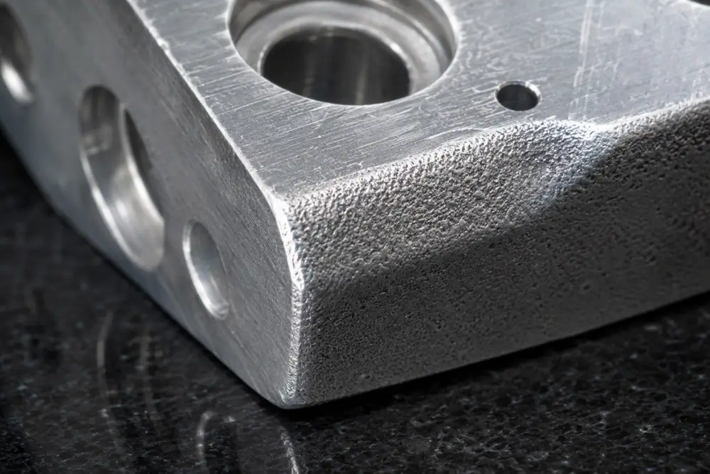
Case Analysis: Dimensional Loss and Edge Erosion on Al6061 Manifolds
A tier-one robotics client contracted Dazao to inspect and salvage a batch of 450 units of five-axis CNC-machined valve manifolds made from Al6061-T6. Sourcing teams looking to understand baseline production budgets can reference our breakdown on aluminum CNC machining cost factors, where post-finishing steps often dictate final project margins. In this case, the original vendor treated surface texturing as an uncontrolled manual cleaning pass.
Before finishing, the parts were routed through an advanced aluminum CNC machining process to establish tight geometric alignments. However, the manufacturing vendor processed the components in a general-purpose blast room using recycled 24-mesh angular chilled iron grit under 6.5 bar (equivalent to 94 psi) line pressure. The resulting damage was catastrophic:
Precision edge breaks measuring 0.2 mm by 45 degrees eroded into uncontrolled irregular fillets between 0.6 mm and 0.9 mm radius, violating the mechanical seal land boundary for internal O-rings.
Internal M4 tapped holes had their lead chamfers completely peened over. Media packed into blind thread bases, seizing thread go-gages during quality verification.
High kinetic energy impact eroded 0.038 mm of parent metal from the mounting faces, driving critical bore center-to-face dimensions outside the drawing tolerance band of plus or minus 0.020 mm.
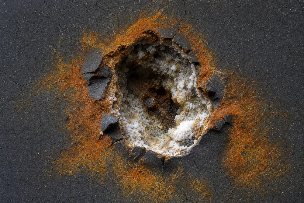
Embedded ferrous particulates triggered galvanic corrosion during subsequent clear sulfuric anodizing, resulting in dark starburst micro-pitting across functional sealing faces.
The entire batch of 450 parts was non-conforming, resulting in an eighteen-thousand-dollar raw material and machine time loss. Treating surface blasting as a minor cosmetic operation permanently alters surface geometry, hardness, and dimensions.
Sandblasting vs Bead Blasting: Micro-Impact Dynamics and Media Selection
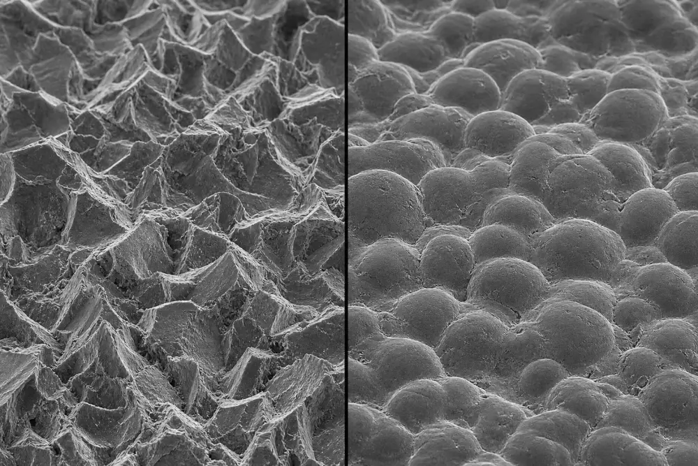
Selecting media requires understanding the mechanical difference between angular abrasion and spherical peening. Engineers evaluating broader workshop finishing methods can consult our aluminum surface finishing guide to compare mechanical media treatments against chemical etching and electropolishing. The industry comparison between sandblasting vs bead blasting highlights two distinct surface interaction modes:
Angular Grit Abrasion vs. Spherical Peening Mechanics
Angular abrasives such as white fused alumina, brown fused alumina, garnet, or crushed glass feature sharp, multi-faceted cutting edges. Upon impact, these particles act as microscopic cutting tools, gouging material via micro-machining and leaving sharp peaks and valleys. This geometry creates the mechanical anchor pattern required when performing sandblasting for coating adhesion.
Spherical media such as soda-lime glass beads, ceramic beads, and conditioned steel shot deliver kinetic energy through rounded geometries. Instead of cutting the substrate, they induce plastic deformation, displacing material radially into hemispherical dimples. This peening action builds compressive residual stresses, closes micro-fissures, and controls sandblasting surface roughness without tearing the parent material.
Industrial facilities have eliminated silica sand due to respiratory silicosis risks and its rapid breakdown into inactive dust. Modern operations utilize engineered media matched to the alloy substrate, hardness, and downstream processing steps. When handling sandblasted aluminum, operators must choose between preserving dimensions or producing aggressive mechanical tooth patterns.
Engineering Abrasive Media Classification
White Aluminum Oxide features a sharp angular shape with a Mohs hardness of 9.0. Typically specified in 80 to 180 mesh sizes, it achieves a surface roughness between Ra 1.6 and 4.5 microns on Al6061, Al7075, titanium, and stainless steels. It delivers a non-contaminating profile for structural adhesive bonding or thin-film coatings.
Brown Aluminum Oxide features sub-angular geometry with a Mohs hardness of 9.0. Operating in 46 to 120 mesh sizes, it generates an aggressive Ra of 2.5 to 6.3 microns on carbon steels and alloy castings. It is the primary industrial standard for sandblasting rust and mill scale removal before thermal spray or heavy industrial primers.
Soda-Lime Glass Bead features a spherical geometry with a Mohs hardness of 5.5 to 6.0. Used in 100 to 200 mesh sizes, it produces an Ra finish between 0.8 and 2.2 microns on non-ferrous metals, brass, and copper. It yields a clean satin aesthetic finish and removes light burrs without removing base metal stock.
Almandine Garnet features sub-angular grains with a Mohs hardness of 7.5 to 8.0. Delivered in 60 to 120 mesh sizes, it produces an anchor profile between Ra 2.0 and 5.0 microns on structural steel fabrications and heavy marine components, balancing high cutting speed with low dust generation.
Silicon Carbide features very sharp angular edges with an extreme Mohs hardness of 9.5. Typically utilized in fine 120 to 240 mesh sizes, it creates an etched surface between Ra 1.0 and 3.2 microns on hardened tool steels, ceramics, and tungsten carbide components.
Plastic Urea and Melamine media feature polyhedral angular geometry with a low Mohs hardness of 3.5 to 4.0. Running in 30 to 60 mesh sizes, it maintains an Ra between 0.4 and 1.2 microns for stripping paint from thin-gauge aerospace skins and composite assemblies without altering base metal dimensions.
Media Breakdown and Work-Mix Control Across Shifts
Abrasive media fractures with every impact against the target workpiece. When utilizing glass beads during sandblasting aluminum parts, spherical beads typically shatter into sharp, jagged fragments after three to five recirculation cycles under 5.0 bar impact pressure.
If quality control teams do not continuously replace spent media, the operating mixture transitions from a spherical peening medium to an irregular, low-mass angular grit. This shift alters the resulting surface texture, creating visible color variations that become glaringly apparent when parts receive black anodized aluminum CNC finishes.
Three Critical Surface Blasting Defects Overlooked by Machine Shops
Standard technical resources focus primarily on cosmetic cleanliness and basic blast speed. However, Dazao engineering data reveals three destructive mechanisms that repeatedly compromise structural, chemical, and coating integrity during production.
Sub-Surface Ferrous Contamination and Anodizing Pitting
Machining facilities processing diverse metals often route carbon steel weldments, cast iron brackets, and precision aluminum components through shared blast equipment. This operational shortcut creates a destructive corrosion mechanism.
When angular media impacts soft non-ferrous metals like Al6061-T6 or Al5052 at velocities exceeding 60 meters per second, sharp particles fracture and embed permanently into the metal matrix. Scanning electron microscope energy-dispersive X-ray spectroscopy analysis demonstrates that up to 14 percent of a blasted surface area can retain embedded abrasive media fragments.
If the blast media was previously used on carbon steel or iron castings, microscopic ferrous dust transfers into the abrasive charge. Under blast pressure, these sub-micron iron particles are driven into the aluminum surface.
When the component later enters a sulfuric acid bath to produce clear anodized aluminum components, or undergoes treatment meeting strict aluminum anodizing thickness and type specifications, these embedded iron particles create localized galvanic cells. The acid bath initiates aggressive galvanic attack around the foreign ferrous inclusion, hydrogen gas evolves rapidly, and the continuous aluminum oxide film fails to form. The outcome is visible starburst micro-pitting, dark halo discolorations, and localized dielectric breakdown.
The Dazao Quality Protocol dictates that aluminum and stainless components are processed in dedicated blast cabinets physically isolated from carbon steel lines. Only fresh, virgin sandblasting media for aluminum such as high-purity white fused alumina or virgin glass beads is approved. Blasted aluminum parts pass through an engineered 15 to 20 percent concentration nitric acid desmut immersion to dissolve tramp metallic ions before entering surface conversion tanks.
Asymmetric Peening Stress and Thin-Wall Deflection Mechanics
Thin-walled structural parts such as electronic chassis, optical housings, and drone frames with section thicknesses below 1.5 mm consistently warp during blast operations due to mechanical stress imbalance.
Every abrasive particle impact acts as a microscopic peening hammer. The localized plastic deformation expands the superficial metal layer laterally, introducing high biaxial compressive residual stresses that penetrate between 0.05 mm and 0.20 mm beneath the surface.
When an operator blasts only the functional exterior face of an asymmetrical CNC component, that side undergoes surface expansion. The unblasted interior surface retains its neutral machining stress profile. To re-establish internal moment equilibrium, the component bows away from the blasted side, resulting in severe flat-plane distortion known as the potato chip effect. The concentrated particle stream expands the upper superficial layer, while the neutral internal core restrains mechanical expansion, forcing the part into a permanent convex profile along the blasted face.
A CNC milled base plate measuring 200 mm by 120 mm by 1.2 mm fabricated from Al7075-T6 can warp up to 0.45 mm along its diagonal plane after a single-sided pass with 80-mesh aluminum oxide at 5.5 bar pressure. This deformation instantly voids position tolerances and planar datum structures.
The Dazao Quality Protocol restricts working blast pressure to a range of 1.8 bar to 2.4 bar for thin-wall components where wall thickness is less than 2.0 mm. The nozzle incidence angle is reduced from 90 degrees to an inclined angle of 45 to 55 degrees, converting normal impact energy into glancing shear force to reduce depth-wise plastification. Blast processing requires alternating, dual-sided passes to balance the compressive stress envelope across both faces. Critical structural parts undergo pre-blast thermal stress-relief annealing to stabilize the internal crystalline matrix prior to surface texturing.
The Ra Value Paradox: Why Passing Ra Causes Coating Delamination
A major misunderstanding in surface engineering involves confusing centerline average roughness (Ra) with functional sandblasting surface profile depth (Rz) and peak count density (Rpc). Reviewing our CNC surface roughness chart and conversion parameters helps clarify how different machining and finishing paths yield radically divergent micro-geometries under identical Ra numbers.
Manufacturing purchase orders frequently state to sandblast before coating to achieve an Ra of 3.2 microns. An inspection technician checks the blasted part using an entry-level stylus profilometer, records Ra 3.1 microns, signs the conformance report, and routes the part to powder application. Three weeks later, the cured powder coat fails standard ASTM D3359 cross-hatch adhesion testing, stripping away in full sheets during initial field assembly.
The failure stems from measuring only the arithmetic mean. Ra averages all surface deviations over a defined evaluation length, obscuring the actual micro-geometry of the peaks and valleys:
Blasting with large glass beads at moderate pressures can produce an Ra of 3.2 microns. However, the surface profile consists of smooth, rounded, dish-shaped craters. There are no microscopic undercuts or jagged overhangs. When powder melted at 200 degrees Celsius flows over this surface, it finds zero mechanical interlock, relying strictly on weak secondary chemical bonds that fail under mechanical shear or moisture intrusion.
Blasting with extra-coarse 24-mesh brown aluminum oxide can also be adjusted to read Ra 3.2 microns if the dwell time is short. However, this creates an aggressive peak-to-valley spread where Rz exceeds 55 microns, featuring sharp, towering peaks. When a standard 60 to 75 micron dry-film thickness powder coat is deposited, the coating flows into the deep valleys, leaving the sharp peak tips covered by less than 10 microns of resin. These micro-peaks rust rapidly or create immediate electrical holiday pinholes.
The Dazao Quality Protocol for all operations involving surface preparation prior to paint replaces single Ra tracking with a dual-parameter requirement. Mean peak-to-valley depth (Rz) is controlled strictly between 25.0 and 45.0 microns for standard 60 to 80 micron powder film specifications. The anchor profile geometry must be generated exclusively using sharp, angular 80-mesh to 120-mesh synthetic aluminum oxide, completely prohibiting spherical glass beads for structural adhesion prep.
Surface Prep Protocol: Mill Scale Removal, Degreasing, and Coating Adhesion
A common failure mode in secondary processing stems from treating mechanical blasting as an isolated cleaning process rather than the initial phase of a multi-stage chemical and mechanical bonding chain. For a complete look at downstream curing, chemistry, and equipment parameters, refer to our in-depth powder coating aluminum parts guide. Achieving long-term adhesion requires coordinating physical roughness with microscopic substrate cleanliness.
Applying mechanical blasting prior to industrial wet painting or powder application increases total surface area by 300 to 500 percent compared to an as-machined or mill-finish face. This surface multiplication creates functional mechanical interlocking. Liquid epoxies, polyurethanes, or melted powder resins flow into the micro-recesses via capillary action. The resin solidifies within the microscopic anchor pattern, forming continuous physical keys that anchor the polymeric film to the metal substrate. This mechanical anchoring prevents delamination under thermal expansion cycles, mechanical vibration, and direct shear impacts. Without sharp, angular micro-crevices, the coating relies entirely on weak interfacial forces that degrade rapidly once atmospheric moisture penetrates the film interface.
Compressed Air Hydrocarbon Contamination and Pinholing Failures
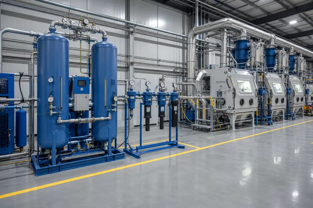
The purity of the compressed air driving the blast nozzle is as critical as the media chemistry. Standard plant air contains aerosolized oil droplets from compressor lubrication, moisture condensation from cooling piping, and piping scale.
When dirty air feeds a blast nozzle, oil droplets atomize and coat each abrasive particle. Under high-velocity impact, these hydrocarbons are forced deep into the freshly exposed, highly reactive metallic peaks and valleys. This thin oil contamination is invisible to the unaided eye.
Once the part enters the powder curing oven at 180 to 205 degrees Celsius, these trapped hydrocarbons vaporize. The expanding gas forces its way through the melting powder layer, causing severe surface defects. It produces microscopic pinholes that punch through the full film thickness, fish-eye craters where fluid coating pulls away from oil droplets, and large delamination regions where carbon residue drops adhesive tensile strength to zero.
To prevent this defect, industrial operations must specify clean air delivery conforming to ISO 8573-1 Class 1.2.1. This standard requires multi-stage filtration including cyclonic bulk separators, dual coalescing oil filters filtering down to 0.01 micron, and refrigerated desiccant drying units maintaining a pressure dew point of minus 40 degrees Celsius.
Environmental Exposure Windows: Managing Flash Rust and Native Oxides
A freshly blasted metal surface exhibits peak chemical activity, leaving it susceptible to rapid atmospheric degradation. Environmental dwell time between surface blasting and downstream finishing must be strictly monitored.
Executing sandblasting before powder coating requires close alignment with the ambient oxidation clock. For carbon steel parts exposed to relative humidity exceeding 60 percent, flash rust initiates in under 45 minutes, demanding staging rooms below 40 percent relative humidity. For precision aluminum parts, chemical conversion or primer booths must be engaged within a 4-hour window to avoid unmanaged, non-uniform hydration of the native oxide film.
For structural steels, cast iron, and hot-rolled components, mechanical oxide stripping removes all passivating mill scale, exposing active ferrite. In humid environments, microscopic ferrous hydroxide crystals develop rapidly at valley bottoms, degrading bond strength before parts reach the paint booth. If parts cannot receive immediate primer or conversion coatings within two hours, they must be stored in humidity-controlled staging areas.
Unlike ferrous alloys, aluminum forms a self-passivating amorphous aluminum oxide layer within milliseconds of atmospheric exposure. Over the subsequent two to six hours, this film thickens from 1.5 nanometers to more than 4.5 nanometers, absorbing atmospheric moisture to convert into hydrated boehmite or bayerite structures. This non-uniform, hydrated native oxide interferes with chemical conversion baths. Dazao quality standards mandate that all blasted aluminum components enter chemical conversion or primer booths within a strict four-hour window following blasting.
Protecting Precision Features: Masking Selection and Edge Containment
Abrasive blasting is non-discriminating. Without engineered masking, abrasive streams strip precision surfaces, erode critical geometric tolerances, and ruin assembly interfaces.
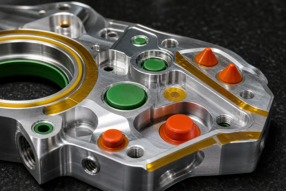
Non-Negotiable Keep-Out Boundaries for Critical Machined Tolerances
Manufacturing drawings must explicitly classify functional regions that forbid direct media impact, especially when maintaining verified aluminum CNC machining tolerances:
Internal and external threads must be shielded because media impact erodes the 60-degree crest profile of metric and UN threads, reducing pitch diameter, rounding lead-in chamfers, and causing thread gage rejection.
O-ring sealing glands demand strict roughness limits between Ra 0.8 and 1.6 microns and sharp corner boundaries with edge breaks under 0.1 mm. Blasting washes out retention corners and increases groove floor roughness, creating leak paths for fluid seals.
Precision bearing bores ground or reamed to ISO fits such as H6, H7, or g6 cannot tolerate the 0.005 mm to 0.030 mm dimensional stock loss caused by blast erosion.
Electrical grounding lands on anodized or plated components requiring bare metal contact zones for EMI shielding must remain pristine and dimensionally planar.
Thermal Adhesive Carbonization and Residue Defect Mitigation
A frequent shop-floor error is selecting masking tapes based on initial adhesion while ignoring thermal and chemical breakdown characteristics.
When low-grade vinyl tapes, standard paper masking tapes, or standard polyester tapes are subjected to angular abrasive bombardment, their backing materials shred rapidly. Media dust penetrates beneath the edges, eroding the boundary of the protected feature.
Worse, mechanical impact breaks the shear bonds of common pressure-sensitive rubber or low-end acrylic adhesives. Microscopic layers of adhesive transfer to the metal substrate along the masking margin. When the component is baked in a powder curing oven at 200 degrees Celsius, the residual adhesive cross-links and carbonizes, forming an inert, glassy residue. The liquid powder coating cannot wet this contaminated band, creating a continuous boundary halo of bare, unbonded metal where moisture migrates and triggers creep corrosion.
The Dazao Masking Protocol approves only two masking material classes:
Molded silicone and EPDM hardware, including reusable tapered plugs, pull-plugs, and blind-hole sleeves rated to 260 degrees Celsius. Plugs are sized 10 to 15 percent larger than hole nominal diameters to maintain positive interference seals under blast cabinet vibration.
High-adhesion die-cut polyimide and woven fiberglass tapes utilizing cross-linked, high-temperature silicone adhesives that peel away with zero residue, leaving clean demarcation lines.
Fluid Jet Acceleration and Sharp Corner Radius Breakdown
Due to the compressible fluid dynamics of supersonic air-abrasive mixtures, particle flow accelerates as it crosses a boundary edge. The blast jet curls over 90-degree outer corners, creating a localized venturi effect that increases particle strike frequency per unit area.
If an operator holds a blast nozzle stationary near a sharp edge, the corner radius expands from a drawing-specified R0.1 mm to R0.6 mm within three to five seconds. To maintain sharp edges on high-precision assemblies, nozzles must be traversed continuously at a 45-degree incidence angle, keeping an offset distance of 150 mm to 200 mm from exposed edges.
Sandblasting Cost Drivers and Standardized Drawing Callout Guidelines
Estimating the sandblasting cost for metal parts requires evaluating labor-intensive prep cycles, processing rates, and mechanical constraints rather than basic machine run time.
Labor Ratios: Manual Masking vs. Automated Turntable Blasting
Evaluating overall finishing expenses involves reviewing the breakdown of operations across production shifts. Manual masking, plugging, and inspection account for 55 to 65 percent of total finishing labor cost. Active blasting chamber dwell time represents 15 to 20 percent of cycle time. Post-blast de-masking, blow-off, and ultrasonic wash stages demand approximately 15 percent of the process cycle. Abrasive media replenishment and dust collector maintenance consume the remaining 5 to 10 percent of operational overhead.
On a multi-axis CNC robotics housing containing 16 blind tapped holes, two bearing pockets, and three ground datum faces, applying plugs and precision tape masks takes four minutes per unit. The actual blast cycle takes 35 seconds. Masking and de-masking account for the dominant majority of total part finishing labor.
Rigid steel structures withstand high-pressure blast passes at 6.0 bar using coarse media at rapid conveyor speeds. Conversely, thin-walled aluminum structures require low-pressure passes at 2.0 bar, dual-sided balanced passes, and extended cycle times to prevent deflection, increasing processing costs.
Symmetrical parts such as brackets and motor end-caps can be processed in batch tumble-blast or automated rotary turntable machines, cutting finishing labor by 70 percent. High-precision components with complex keep-out zones demand dedicated, single-piece manual handling in glovebox blast stations.
Standardized Technical Notes for RFQs and CAD Drawings
To guarantee reliable quality and prevent pricing disputes during quoting, eliminate vague phrases like sandblast to finish. Instead, incorporate precise, measurable engineering instructions across drawing notes:
Regarding media chemistry, specify 120-mesh high-purity virgin White Fused Alumina with an aluminum oxide purity of at least 99.5 percent, which prevents substrate contamination and chemical discoloration.
Regarding surface profile depth, specify a target Rz between 30 and 40 microns, Ra between 2.5 and 3.2 microns, and a minimum peak count density of 50 peaks per centimeter, ensuring an adequate mechanical anchor pattern for coating adhesion.
Regarding feature protection, mandate masking on all threaded holes, O-ring groove glands, and bearing bores per specific drawing zone details, eliminating dimensional stock loss and preserving seal geometry.
Regarding particulate cleanliness, specify ultrasonic cleaning in deionized water followed by an air blow-off certified to ISO 8573-1 Class 1, eliminating residual media dust and hydrocarbons prior to coating.
Regarding the post-blast process window, mandate the application of conversion or primer coating within four hours of blast completion, preventing flash rusting on steel and uncontrolled hydration on aluminum surfaces.
Integrating Mechanical Surface Preparation into Upstream DFM Reviews
Surface preparation is not a detached, post-machining operation. It is an interdependent manufacturing step that directly governs dimensional integrity, cosmetic repeatability, and the fatigue life of high-performance components. Sourcing teams can review foundational aluminum CNC machining design rules to optimize wall thicknesses, tool clearances, and corner radii before finalizing prints.
When product designers and sourcing teams consider abrasive selection, micro-profile metrics, and masking protocols early in the design-for-manufacturing phase, they eliminate dimensional scrap, prevent late-stage coating failures, and stabilize production costs.
At Xiamen Dazao Machinery, our precision machining and surface finishing infrastructure reflects over 24 years of manufacturing practice. Operating under certified ISO9001:2015 and IATF16949:2016 quality management systems, our facility integrates multi-axis CNC milling and turning with segregated, high-purity surface preparation cells.
By applying disciplined engineering controls across media integrity, air purity, surface profiling, and precision masking, our team ensures that every production batch meets rigorous performance and dimensional standards.

FAQs
01.Why does sandblasted aluminum develop dark spots after clear anodizing?
02.How do you prevent thin-walled CNC machined parts from warping during blasting?
03.Why does powder coating peel off metal parts that passed Ra roughness checks?
04.How does compressed air quality cause pinholes in post-blast powder coatings?
05.What masking method protects threaded holes and bores from high-pressure blast damage?
06.How does recycled abrasive media degrade surface finish consistency across production runs?