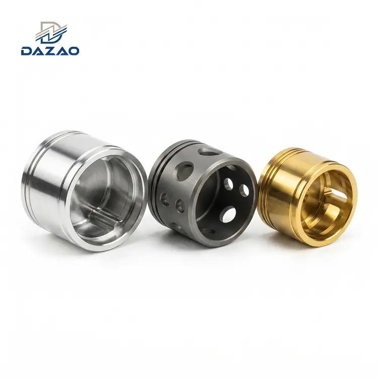
Precision CNC components frequently pass Coordinate Measuring Machine (CMM) dimensional verification only to fail mechanical assembly due to post-finish surface accumulation. Applying powder coating aluminum finishes introduces 60 to 120 microns (0.0024 to 0.0047 in) of dry film thickness per surface, reducing internal bore diameters by up to 0.24 mm and locking unguarded fastener points. Ensuring proper assembly fit demands pre-machining offset compensations, thermal-expansion-matched masking on functional mating faces, and vacuum degassing to eliminate micro-porosity outgassing.
The Dimensional Disconnect Between Machining and Surface Finishing
A recurring breakdown in mechanical contract manufacturing occurs when high-precision components verify within positive or negative 0.01 mm on the coordinate measuring machine inside a climate-controlled inspection cell, yet seize completely on the assembly line. The technician is left forcing a hardened stainless steel dowel pin into an interference-fit bore with a dead-blow hammer.
The underlying problem stems from treating surface finishing as a cosmetic afterthought rather than an additive manufacturing step. Mechanical engineers frequently specify powder coating aluminum parts for exterior durability, UV stability, and impact resistance without factoring in physical mass accumulation. Unlike standard chemical conversion or Type II sulfuric anodizing, which converts the underlying base metal and results in dimensional growth of only 5 to 15 microns per surface, a standard thermoset polymer layer adds substantial material. Selecting the proper alloy temper requires balancing machinability with coating performance, as detailed in our technical aluminum CNC machining guide.

In precision robotics, optical housings, and automotive electronic enclosures, failing to plan for powder coating for CNC machined parts results in tapped threads seizing, O-ring sealing gland distortion, and coplanarity failure across structural mounting interfaces. When a batch of high-precision mounting plates made from Al6061-T6 requires secondary manual tap-chasing and chemical stripping to restore dimensional limits, production schedules collapse and operational budgets evaporate.
Avoiding these failures requires viewing the finishing operation through a strict Design for Manufacturing (DFM) lens. True process control demands engineering the component around the physical realities of electrostatic powder deposition, resin flow dynamics during thermal curing, and micro-scale masking boundaries.
Powder Coating Thickness Dynamics: Managing CNC Tolerance Stack-Up and Edge Buildup
Understanding the spatial impact of polymer deposition begins with dry film thickness measurements. While architectural panels tolerate loose film boundaries, industrial powder coating thickness on structural parts must be tightly quantified to preserve kinematic fit.
Standard single-surface film builds range from 60 to 120 microns (0.0024 to 0.0047 in). Across two opposing faces, this translates to an external boundary increase of 120 to 240 microns (0.0048 to 0.0094 in). Correspondingly, unmasked internal bores experience a diametrical reduction of 120 to 240 microns.
The deposition of organic polymers via electrostatic spray guns relies on charging atomized particles to negative potentials between 60 kV and 100 kV. The grounded aluminum substrate attracts these particles until the electrical resistivity of the deposited powder layer repels further accumulation. During the cross-linking phase inside the curing oven at 180°C to 200°C (356°F to 392°F), this powder melts, flows, and solidifies into a continuous protective shell.
Faraday Cage Shielding and Geometric Coating Disparity
Dry film thickness is never uniform across a complex three-dimensional CNC geometry. Internal corners, narrow pockets, deep recesses, and high-aspect heat sink fins exhibit the Faraday cage effect.
The external electric field lines take the path of least electrical resistance, concentrating aggressively at sharp external corners, exterior ribs, and peripheral faces. Conversely, electrostatic field lines fail to penetrate deep interior cavities, leaving internal corners with dry film thicknesses as thin as 25 to 35 microns, or completely un-coalesced.
Concurrently, the extreme edge of the part experiences excessive accumulation known as edge build-up or fat edge. Due to focused field intensity at sharp radii, the polymer layer at external edges frequently reaches 160 to 200 microns.
|
Geometric Feature |
Expected Film Thickness (μm) |
Resulting Dimensional Shift |
Assembly Impact Without Compensation |
|
Flat External Face |
70 to 90 μm |
+0.070 to +0.090 mm per face |
Nominal displacement; minor stack-up issue |
|
External Sharp Corner (< R0.5 mm) |
140 to 190 μm |
+0.280 to +0.380 mm across corner |
Tilting of mating brackets; binding at housing interfaces |
|
Deep Internal Pocket (Aspect Ratio > 2:1) |
25 to 45 μm |
+0.025 to +0.045 mm per face |
Potential corrosion risk; partial dielectric breakdown |
|
Unmasked Reamed Hole (H7 Tolerance) |
60 to 110 μm |
-0.120 to -0.220 mm on diameter |
Total mechanical seizure of dowel pins or shafts |
|
Unmasked Metric Tapped Hole (e.g., M6x1.0) |
50 to 90 μm |
Severe thread profile reduction |
Fastener cross-threading, galling, or binding |
Sharp Edge Build-up: Mitigating Mating Face Tilting and Mechanical Pre-Stress
Industry literature routinely points out that powder coat adds thickness, but rarely explores the mechanical tilt induced by localized edge accumulation. Designing external edge fillets with generous radii prevents electrostatic field crowding, aligning with principles established in our aluminum CNC machining design guide.
When two structural aluminum plates machined to a flatness specification of 0.02 mm are powder-coated without planar perimeter masking, the extreme perimeter accumulates an extra 60 to 100 microns relative to the central expanse. The resulting surface profile features an unintended crown around the outer perimeter.

When technicians bolt these two components together on an assembly jig, the raised, hardened polymer perimeters touch first, acting as a structural fulcrum. Torque applied to center or peripheral fasteners introduces mechanical bending stresses directly into the Al6061-T6 substrate.
In precision optical mounting tables or multi-axis robotics bases, this distortion destroys sensor alignment, introduces angular runout, and bends the internal plane beyond operational limits.
CAM-Driven Machining Offsets for Post-Coating Fit
At Xiamen Dazao Machinery, eliminating assembly interference is handled upstream in the CAM environment rather than on the assembly bench. Programmers must compensate for post-finish film accumulation by referencing our aluminum CNC machining tolerances guide before cutting metal:
· Internal Cylindrical Clearance: Bores intended for non-press-fit shafts that must receive powder coating are bored oversize during CNC turning or milling. The machining offset accounts for twice the nominal coating target thickness plus the upper process variance.
· External Datum Clearance: Critical mounting steps that must be fully coated are milled down by the upper limit of the expected film thickness, preventing the surface envelope from violating the Maximum Material Condition (MMC) set by GD&T callouts. Dimensional compensation on cylindrical shafts is executed through our dedicated high-precision CNC turning operations.
· Precision Milling Offsets: Our production floor deploys advanced precision CNC milling services to cut step-down offsets into raw housings prior to the coating bay.
· Corner Radius Modification: Outside corners on components requiring overall coating are programmed with a minimum radius of 1.0 mm to 1.5 mm. Eliminating razor-sharp edges diffuses the electrostatic field gradient, suppressing the fat-edge phenomenon and keeping perimeter buildup within 15% of the nominal face thickness.
Precision Masking for CNC Parts: Protecting Threaded Holes, Bores, and Datum Faces
Threaded interfaces and precision-ground locating features are the most common failure points on post-finish parts. Implementing robust powder coating masking for CNC parts protects critical features and eliminates downstream repair costs.
Allowing thermoset polymer to enter powder coating threaded holes creates severe assembly failures. Chasing cured polyester or polyurethane resin out of an M4 or M5 blind hole using a hand tap is bad engineering practice.
The hardened polymer chips into micro-particulates rather than cutting cleanly. When the finished part goes into service inside a high-speed robotics gearbox or vacuum chamber, these trapped abrasive powder flakes vibrate loose, enter linear guide rails, contaminate lubricants, and cause catastrophic bearing seizure.

Thread Protection Realities: Avoiding Abrasive Debris and Chipped Powder
Chasing threads after curing damages the internal lead chamfer and strips protective pre-treatment skins. Residual powder fines remain wedged within the roots of threads, generating high frictional resistance when mating stainless steel fasteners are driven home.
This frictional spike frequently causes galling and thread strip-out in soft aluminum matrix structures. Upfront insertion of dedicated masking hardware eliminates the need for secondary cutting tools.
Sizing Masking Hardware: High-Temperature Silicone Plugs vs. Polyimide Films
Masking operators rely primarily on two baseline products: custom-molded high-temperature silicone rubber plugs and polyimide (Kapton) pressure-sensitive adhesive tapes rated for 200°C continuous exposure.
Sizing these elements requires extreme care. For small metric threads from M3 to M8, standard tapered silicone plugs present a persistent failure mode:
· If the plug is undersized, the aggressive airflow from the manual or robotic powder spray gun dislodges it, leaving the internal threads exposed to full powder deposition.
· If the plug is oversized and forced into a blind hole, the trapped air pocket within the hole heats up inside the curing oven from 20°C to 200°C. Trapped air expands substantially under this thermal load, blowing the plug out mid-cure and depositing molten overspray into the thread run-out.
|
Hole Feature Type |
Recommended Masking Solution |
Operational Risk During 200°C Cure |
Dazao Preferred Countermeasure |
|
Through Thread (M3 to M8) |
Dual-tapered solid silicone pull plug |
Paint bleed along entry chamfer |
Pull plug with integrated sealing washer collar |
|
Blind Thread (M3 to M8) |
Hollow or vented silicone push plug |
Thermal air expansion pushing plug outward |
Vented plug with secondary spiral relief channel |
|
Precision Reamed Dowel Hole |
Precision-ground stepped silicone plug |
Edge bleed destroying slip fit |
Plug diameter matched to 105% of maximum bore diameter |
|
Flat O-Ring Face / Ground Datum |
Die-cut polyimide disc with silicone adhesive |
High-heat adhesive residue transfer |
Precision die-cuts applied with 2.0 kg/cm ² roller pressure |
Thermal Expansion Mismatch, Boundary Tearing, and O-Ring Sealing Ridges
A major problem rarely analyzed in finishing literature is the physical tearing of the coating boundary caused by the thermal expansion mismatch between masking materials and aluminum substrates during cool-down.
Aluminum Al6061-T6 has a linear Coefficient of Thermal Expansion (CTE) of approximately 23.5 micro-strain per degree Celsius. Silicone masking plugs display a CTE greater than 200 to 300 micro-strain per degree Celsius. As the cured component exits the oven, the silicone shrinks much faster than the surrounding metal.
If the technician removes the masking plug or polyimide tape after the component has fully cooled to ambient room temperature, the brittle, fully cross-linked polymer film that bridged the junction between the mask and the raw substrate shatters. This leaves a micro-fractured, jagged edge that promotes progressive sub-film corrosion and flaking under environmental stress.
Conversely, if the masking is stripped while the part is still at peak oven temperature, the molten polymer strings out, forming structural threads that weld onto clean ground datum surfaces.
Furthermore, where polyimide tape protects a planar face, such as a circular O-ring gland, the liquid resin accumulates against the tape edge, forming a physical ridge upon curing. This boundary step commonly reaches 0.12 to 0.18 mm in height. When an elastomeric O-ring is compressed against this stepped transition, the uneven localized pressure gradient induces leak paths across fluid-power manifolds, resulting in hydrostatic pressure failure.

Standardized Extraction Protocols within the Controlled Cooling Window
To prevent masking line failure, Xiamen Dazao Machinery enforces a standardized operational protocol across all precision milling and turning orders:
· Flanged Pull-Through Plugs: We replace standard tapered plugs with flanged silicone pull plugs. The integrated shoulder sits flat against the entry chamfer of the threaded hole, preventing the electrostatic arc from building up on the lead thread.
· Controlled De-Masking Temperature Window: Masking extraction is restricted to parts holding a surface temperature between 45°C and 55°C (113°F to 131°F). Within this target zone, the polymer resin is structurally solid but retains sufficient elasticity to cut cleanly at the masking boundary without chipping or micro-fracturing.
· Die-Cut Step Offsets: For critical O-ring grooves and sealing interfaces, our CAD/CAM engineers generate custom die-cut tape overlays with a 0.5 mm offset away from the actual elastomeric sealing contact boundary, ensuring that the O-ring makes 100% flat contact with bare, un-bridged aluminum.
Powder Coating Adhesion on Aluminum: Chemical Pretreatment and Outgassing Root Causes
Achieving permanent powder coating adhesion on aluminum surfaces is significantly more complex than painting structural carbon steel. Aluminum naturally generates a passivation layer of aluminum oxide (Al2O3) almost immediately upon exposure to atmosphere.
While this native oxide resists light atmospheric corrosion, it lacks mechanical cohesion and electrical consistency. Applying powder directly over raw, untreated CNC aluminum parts guarantees total coating delamination under thermal cycling or shear loading.
Conversion Coating Pretreatment: From Alkaline Etch to Zirconium Nanotechnology
A dependable bond requires an engineered conversion coating interface. Surface conversion forms the foundation of adhesion, bridging the mechanical profiles analyzed in our technical aluminum surface finishing guide. The bare part must pass through a strict multi-stage chemical pretreatment line:
The process sequence begins with an alkaline wash operating between pH 9.5 and 11.0 at 50°C to 60°C to strip cutting oils, coolants, and machine lubricants. A deionized water cascade rinse removes residual surfactants. An acid deoxidizer and etch, using a nitric or phosphoric base, strips away the inconsistent native oxide layer.
The substrate then undergoes fluorotitanic or zirconium nanotechnology conversion, forming an amorphous organometallic conversion layer between 15 and 40 nanometers thick. The sequence finishes with an ultra-pure deionized rinse holding conductivity below 20 microsiemens per centimeter, followed by a moisture dry-off oven cycle at 110°C to 120°C.
This chemical architecture delivers the microscopic anchor profile required for the molten polymer to mechanically key into the metal during curing. This bond allows components to pass the ASTM D3359 Cross-Hatch Adhesion Test at the maximum 5B rating, as well as surviving 1,000 hours of ASTM B117 neutral salt spray testing without sub-surface filiform corrosion creep.
Rheological Flow Dynamics and Powder Coating Orange Peel Defects
The aesthetic and functional defect known as powder coating orange peel defects refers to an irregular, wavy topography resembling the skin of a citrus fruit, rather than a mirror-smooth or engineered matte finish.
This condition occurs when the viscosity of the melting powder does not stay low enough, long enough, during the heat-up cycle to allow natural surface tension to achieve complete self-leveling. The primary drivers of this defect are:
· Overly Aggressive Oven Ramp Rates: If the heating chamber brings the part to the 200°C cross-linking temperature too rapidly, the resin undergoes chemical cross-linking before it has completely finished flowing, locking in flow waves.
· Excessive Transfer Efficiency Voltage: Excessive electrostatic gun voltage (above 85 kV) accelerates the arrival of dry powder, creating electrical back-ionization that traps microscopic air charges within the pre-cured layer.
· Substrate Roughness Disparity: If milled scallops exceed Ra 3.2 microns per the metrics in our CNC surface roughness chart guide, the molten polymer fails to bridge the micro-peaks, printing through as a wavy topography.
Blind-Hole Outgassing, Coolant Flashing, and Micro-Porosity Crater Rupture
The most insidious defect in precision CNC components is the explosive outgassing of trapped air and chemical residues during high-temperature curing, which results in volcanic cratering, pinholes, and blistering.
Ambient air and moisture at 20°C expand mechanically by more than 1.6 times at 200°C. More critically, residual liquid water and cutting solvents experience a liquid-to-vapor expansion exceeding 1500 times inside the curing chamber.
When high-speed CNC milling cutters carve deep blind holes or narrow cavities into aluminum bar stock or plate, cutting fluids, tramp oils, and coolants get driven deep into the roots of threads and micro-crevices under high fluid pressure. Standard room-temperature cleaning dissolves surface oil but often fails to displace high-pressure fluids trapped in the base of high-aspect-ratio holes.
When the masked or semi-masked part is suspended inside the curing oven at 200°C, these volatile compounds vaporize. The resulting pressure spike forces expanding steam and gas straight past the boundaries of masking plugs or right through the semi-liquid, curing polymer matrix.

The gas ruptures the smooth polymer skin. Because the curing reaction is already advanced, the viscosity is too high for the fluid to re-flow over the void. What remains is a permanent microscopic pinhole extending down to raw aluminum.
This issue is amplified when finishing cast aluminum parts (such as A380 or ADC12) or porous heavy-gauge aluminum tooling plate, where interior gas pockets naturally open up during machining.
Deep-Cavity Thermal Degassing and Ultrasonic Decontamination
To guarantee zero-porosity finishes on complex components, Xiamen Dazao Machinery enforces a preventative thermal cycle:
· Ultrasonic Solvent Displacement: Highly complex housings and manifold blocks undergo multi-frequency ultrasonic cleaning in solvent tanks to draw coolants and residues out of blind pockets.
· Mandatory Thermal De-Gassing Pre-Bake: Prior to powder application, the raw parts undergo a pre-bake cycle at 210°C to 220°C (10°C to 20°C above the actual cure cycle temperature) for 30 to 45 minutes. This process intentionally forces all trapped air, internal moisture, and embedded hydrocarbons to volatilize and evacuate the core.
· Powder Application on Declining Heat: For problem materials, electrostatic deposition begins while the parts are cooling within a 45°C to 50°C window. This ensures that residual air within any micro-porosity is contracting rather than expanding as the part heats back up in the curing oven, preventing outgassing blisters and surface pinholes.
Powder Coating vs. Anodizing Aluminum: Technical Trade-Offs and Total Cost Breakdown
Selecting between powder coating vs anodizing aluminum requires evaluating mechanical tolerances, dielectric properties, operational wear, and total manufacturing expenditure. While our aluminum anodizing guide detailing types and thickness breaks down molecular oxidation boundaries, powder deposition behaves as an added spatial layer.
Type II and Type III (Hardcoat) anodizing electrochemically converts the surface of the aluminum into an aluminum oxide ceramic matrix. For applications requiring extreme surface hardness with minimal outward growth, our Hard anodizing Type III thickness guide explains how electrochemical penetration maintains precise shaft fits.
Powder coating adds 60 to 120 microns of material outward per coated face, with zero inward penetration of the base alloy.
|
Performance Attribute |
Type II Sulfuric Anodizing |
Type III Hardcoat Anodizing (MIL-A-8625) |
Industrial Thermoset Powder Coating |
|
Dimensional Growth per Surface |
5 to 15 μm (0.0002 to 0.0006 in) |
25 to 30 μm (0.0010 to 0.0012 in) |
60 to 120 μm (0.0024 to 0.0047 in) |
|
Surface Hardness Rating |
~300 to 400 HV |
~450 to 550 HV (60 to 65 HRC equivalent) |
2H to 4H Pencil Hardness |
|
Abrasion & Sliding Wear Resistance |
Moderate |
Exceptional (low coefficient of friction) |
Poor under direct friction; susceptible to gouging |
|
Impact & Stone Chipping Resistance |
Brittle; micro-cracks under localized denting |
Brittle; prone to spalling under direct impact |
High impact absorption; ductile polymer deformation |
|
Corrosion Resistance (ASTM B117) |
336 hours (with nickel acetate seal) |
1,000+ hours (with dichromate seal) |
1,000 to 2,500+ hours (pretreatment dependent) |
|
Dielectric Breakdown Strength |
Moderate (~1,000 V) |
High (~1,500 to 2,000 V) |
Extreme (> 5,000 V insulation barrier) |
|
Surface Defect Masking Ability |
Zero; highlights CNC tool paths and defects |
Minimal; reveals substrate grain structure |
Extreme; completely conceals machine marks (Ra 3.2 μm) |
Structural Mechanics: Conversion Layer Growth vs. Polymeric Encapsulation
The fundamental mechanical divide between the two processes is how they handle impact and friction. Anodized layers are brittle ceramics that perform well under sliding wear but micro-crack under mechanical impact or substrate bending.
Powder coats are elastic polymer chains that deform under impact, absorbing energy without spalling. However, powder coatings perform poorly under unlubricated mechanical sliding contact, making them unsuitable for rotating shafts or internal slide ways.
Dissecting Powder Coating Cost: Why Manual Masking Drives 70% of Labor
A common misconception among procurement specialists is that total powder coating cost is dictated solely by powder resin pricing per kilogram or line conveyor throughput speed. On raw sheet metal stampings or large structural weldments with minimal tolerances, coating application accounts for the bulk of the expense. Manual tap chasing and secondary rework directly drive up unit expenses beyond standard machining rates evaluated in our aluminum CNC machining cost guide.

For complex CNC components, manual labor associated with masking and secondary thread remediation represents between 60% and 75% of the total finishing invoice. When an enclosure features 30 individual tapped blind holes, 4 reamed dowel locations, 2 internal bearing bores, and an uninterrupted perimeter O-ring groove, the finishing cycle shifts from automated painting to meticulous micro-assembly:
· Plug Insertion and Sealing Inspection: An operator manually sizes, presses, and verifies 36 unique silicone masking elements per part.
· Die-Cut Alignment: Applying custom polyimide film tape across complex 3D split-lines requires steady manual alignment under magnification.
· Thermal Demasking Labor: Stripping masking while the part rests within the 45°C to 55°C window requires controlled extraction using non-marring brass tools to avoid scoring the aluminum.
· Secondary Thread Chasing: If a single plug fails or leaks under oven pressure, manual restoration using metric hand taps adds direct shop-floor hours.
On complex multi-cavity parts, chemical pretreatment accounts for approximately 8% to 12% of finishing cost, powder raw materials contribute 10% to 15%, curing energy accounts for 10% to 15%, and precision manual masking labor consumes 58% to 72% of the finishing cost allocation.
Engineering Decision Criteria for Critical Aerospace and Industrial Assemblies
Specify powder coating when the component requires:
· High impact resistance, gravel deflection, or flexural resilience without brittle micro-fracturing (e.g., automotive suspension brackets, commercial drone airframe chassis, exterior battery enclosures).
· Complete concealment of aggressive CNC milling scallops, weld seams, or material blending transitions without requiring fine secondary mechanical polishing.
· High dielectric isolation to prevent current leakage or short circuits across high-voltage industrial enclosures.
· Broad availability of specific RAL color targets, textured finishes (matte, fine sand, coarse wrinkle), and gloss levels.
Enforce Type III Hardcoat Anodizing when the component requires:
· Preservation of tight machining tolerances without manual masking labor (e.g., retaining H7 internal bore limits, sliding guide channels, and high-pitch fine threads).
· High sliding abrasion resistance where moving metal-on-metal or seal-on-metal contact occurs (e.g., hydraulic spool valve housings, pneumatic cylinders, linear actuator slides).
· Uniform dimensional change across internal complex fluid passages that an electrostatic spray gun cannot reach due to the Faraday cage effect.
Powder Coating Specifications for Drawings: DFM Callouts, Racking Grounds, and RFQ Accuracy
Bridging the gap between engineering intent and surface-finishing execution requires unambiguous technical drawing documentation. Ambiguity in drawing notes is the primary driver of unexpected supplier charges, lead-time extensions, and out-of-tolerance rejections.

Drawing Title Block Notations: Pre-Plate vs. Post-Plate Tolerancing
When releasing manufacturing documentation for precision parts, standard notes calling out Powder Coat Black without dimensional qualification must be replaced with strict powder coating specifications for drawings:
· Resin Chemistry and System: Specify the exact polymer composition based on end-use environment (e.g., Superdurable TGIC-Polyester for UV outdoor exposure; Epoxy-Polyester hybrid for indoor chemical resistance; Pure Epoxy for chemical immersion).
· Color and Gloss Rating: Identify the RAL color index and specify the specular gloss percentage measured at a 60-degree incident angle per ASTM D523 (e.g., RAL 9005 Jet Black, Semi-Gloss 60% plus or minus 5%).
· Dry Film Thickness Boundaries: Define an explicit operational window rather than a vague nominal value (e.g., Total Dry Film Thickness: 70 μm to 100 μm on designated functional surfaces).
· Dimensional State Clarification: State unequivocally whether drawing dimensions and geometric tolerances apply before surface coating (pre-plate/pre-coat) or after final curing (post-finish). Under ASME Y14.5 standards, if not explicitly noted, dimensional limits apply after finishing, forcing the machining facility to absorb the film thickness offset.
Technical drawing specifications should explicitly state the finish standard (such as Qualicoat Class 2), resin family, exact RAL color and 60-degree gloss tolerance, approved film thickness range, and define that all dimensions apply after surface finishing with the exception of hatched masking areas and internal threads. Drawing notes must also set maximum allowable overspray boundaries (typically positive or negative 0.5 mm) and cap edge ridge heights at 0.05 mm.
Defining Racking and Grounding Locations to Prevent Crevice Corrosion
A primary failure point rarely addressed on customer drawings is the omission of designated hanging and electrical grounding locations.
Electrostatic powder coating relies on a continuous electrical circuit between the part and the conveyor earth ground. If the technical drawing does not specify approved racking locations, finishing line operators will improvise.
They typically insert steel suspension hooks into the most convenient opening, such as a counterbore, a precision dowel hole, an internal O-ring groove, or an internal M6 thread.
This introduces three failure modes:
· Mechanical Distortion of Bores: Heavy aluminum blocks hanging from soft-radius hooks inside a 200°C oven can experience localized contact deformation, damaging roundness tolerances on reamed holes.
· Missing Coverage Shadow: The area shielded by the contact hook receives zero powder, leaving an un-coalesced bare spot.
· Severe Localized Galvanic and Environmental Corrosion: In marine, automotive underbody, or industrial environments, leaving bare aluminum exposed at an unpainted hook point adjacent to an exposed boundary creates a natural focal point for moisture retention. Under salt spray exposure, this unsealed contact point becomes the primary initiation site for filiform corrosion, causing blistering that creeps beneath the sound coating layer.

Dazao Production-Ready RFQ Verification Matrix
To eliminate uncertainty during quoting and prevent engineering change orders midway through production, Xiamen Dazao Machinery evaluates incoming RFQs against a standard six-point verification matrix. Every batch of coated aerospace parts undergoes strict mechanical verification within our certified IATF16949 and ISO9001 quality management framework:
1. Substrate Alloy and Temper: Are we machining Al6061-T6, Al7075-T6, or cast A380? Al7075 exhibits distinct thermal sensitivity; prolonged exposure to 200°C curing can alter heat treatment characteristics if not factored into the cycle.
2. CAD Masking Model Segregation: Does the file package include a step file or 2D overlay defining non-coating zones with hatched boundaries, or is masking interpretation left to shop discretion?
3. Internal Bore and Thread Treatment: Are all internal threads identified as masked, plugged, or chased after coating?
4. Designated Hanging Strategy: Has the customer identified a non-cosmetic, non-functional surface (such as an internal rib or dedicated tooling hole) to serve as the electrical grounding contact point?
5. Quality Verification Standards: Which testing protocols govern lot acceptance (e.g., Cross-Hatch Adhesion ASTM D3359 Method B, Solvent Rub Resistance MEK ASTM D5402, Impact Flexibility ASTM D2794)?
6. Packaging and Edge Protection: Are parts routed for individual pocket cellular packaging to prevent edge chipping during transit?
Conclusion: Eliminating Surface Finishing Risk Upstream
Achieving optimal results when manufacturing coated precision components requires treating the finish as an integrated structural layer. Machine shop performance is not defined solely by spindle speeds, feed rates, and raw part dimensions measured off the deburring station. True precision manufacturing requires accounting for the physical dimensions added by subsequent finishing processes.
At Xiamen Dazao Machinery, our engineering team identifies and resolves dimensional stack-up conflicts before raw aluminum stock enters the 5-axis CNC machining centers. By programming pre-machining clearances into internal features, engineering custom silicone masking tooling, managing thermal degassing cycles to eliminate pinholing, and controlling de-masking temperatures, we ensure that every delivered component mates smoothly during final assembly.

FAQs
01.How do you prevent silicone plugs from blowing out of blind holes during oven curing?
02.Why do threaded holes seize after powder coating even when tapped clean?
03.How do you eliminate jagged tearing along high-temperature masking tape lines?
04.What causes pinhole cratering when powder coating heavy CNC aluminum blocks?
05.Why do unassigned racking and grounding points fail environmental salt spray tests?
06.How much pre-machining offset should be applied to bearing bores receiving powder coat?