
Achieving a repeatable, high-density black anodized aluminum finish requires precise alignment between base alloy metallurgy, chemical bath parameters, and pre-machining dimensional offsets. While standard Al6061-T6 produces pitch-black optical saturation via MIL-A-8625 Type II sulfuric anodizing (12 to 20 µm), high-strength alloys like Al7075 and Al2024 introduce zinc and copper intermetallics that skew colors toward olive-gray or induce surface pitting. For wear-intensive components, Type III hardcoat anodizing yields 450 to 600 HV surface hardness but alters the color spectrum toward charcoal black due to its dense, self-colored oxide structure. Engineering drawings must explicitly define whether dimensional tolerances apply before or after surface treatment, accounting for an exact 50/50 coating penetration-to-growth ratio per surface.
Precision CNC components specified with a black anodized aluminum surface frequently suffer from high rejection rates during incoming quality control inspections. Procurement teams often encounter issues such as purple or bronze tint variations, stripped internal threads, uneven gloss, and blotchy pigment distribution. These surface defects are rarely chemical bath accidents alone; they stem directly from machining stress, microstructural differences in the base material, improper post-machining prep, and incorrect callouts on manufacturing prints.
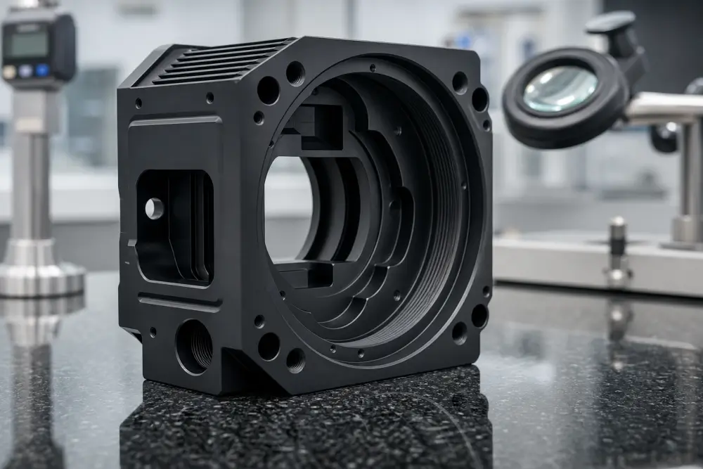
At Xiamen Dazao Machinery, producing precision components for robotics, aerospace, medical devices, and automated test equipment has shown that black anodizing is not simply a decorative color bath. It is an electrochemical conversion process that permanently alters component dimensions, surface hardness, electrical conductivity, and heat transfer efficiency. Controlling the final finish requires an understanding of how base alloy composition, sulfuric bath parameters, and machining toolpaths interact at the microscopic level.
Why Black Anodized CNC Parts Fail Quality Inspections?
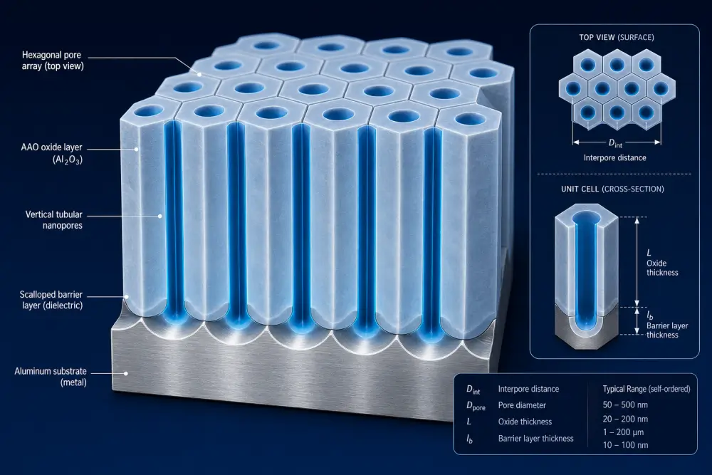
Many custom mechanical assemblies fail final inspection not because of basic CNC machining errors, but because surface finishing was treated as an isolated, downstream step. A uniform surface layer consists of a porous aluminum oxide hexagonal cell structure generated through controlled anodic oxidation, impregnated with organic or inorganic black dye, and sealed in nickel acetate or hot deionized water. When engineering teams balance industrial aluminum surface finishing options during the design stage, three primary mechanical failures must be actively prevented:
1. Dimensional Growth and Tolerance Stack-up: Anodic oxide films grow outward from the original aluminum boundary while simultaneously penetrating inward. On high-precision press-fit bores such as H7 locations or fine external threads, an uncalculated coating buildup causes thread binding, undersized diameters, or shaft seizure during cleanroom assembly. Controlling machining tolerance stack-up controls for aluminum must start at the CAD modeling stage rather than in the plating shop.
2. Dielectric Isolation on Grounding Points: Anodic coatings are electrical insulators with dielectric breakdown voltages ranging from 500V to over 1500V. Components requiring RF shielding, ESD dissipation, or chassis grounding fail functional testing unless masking callouts are clearly defined on the engineering print before machining.
3. Visual Inconsistency Across Assemblies: Mating parts assembled on the same industrial chassis often show mismatched black shades under daylight versus factory LED lighting. These visual rejections occur when different manufacturing facilities use disparate alloys, varying blast media, or conflicting anodizing specifications, such as mating a Type II dyed part with a Type III hardcoat part.
Designing components for consistent black anodizing requires treating raw material selection, toolpath strategy, surface texturing, and anodizing chemistry as an integrated manufacturing system.
Aluminum Alloy Selection for Black Anodizing: Metallurgy and Dye Uptake
The choice of raw material dictates the final appearance, saturation, and corrosion resistance of the anodic layer. Not all aluminum alloys accept dyes identically. Selecting the best aluminum alloy for black anodizing requires evaluating the chemical composition and the presence of alloying elements like copper, zinc, silicon, and magnesium. Incorporating sound precision aluminum CNC machining practices ensures that surface stress does not disrupt this electrochemical reaction.
During the anodic run, the pure aluminum matrix oxidizes into transparent aluminum oxide. Alloying elements, however, do not oxidize at the same rate. Some intermetallic compounds dissolve into the sulfuric acid, creating microscopic voids; others resist oxidation, becoming trapped within the cell matrix and scattering light, which causes noticeable black anodized aluminum color variations.
Detailed Alloy Performance Comparison
6000-Series Alloys (Al6061, Al6082)
Al6061-T6 and Al6082-T6 are industry standards for visual and functional anodizing. With magnesium and silicon balanced to form magnesium silicide, the resulting anodic layer remains clear and transparent. This allows black organic dyes to penetrate deeply into the hexagonal pores, yielding a rich, uniform, jet-black appearance. Surface defects in 6000-series alloys typically result from machining tool marks or heat streaks rather than chemical incompatibilities.
7000-Series Alloys (Al7075, Al7050)
Widely used in aerospace and robotics for their high strength-to-weight ratios, 7000-series alloys contain high weight percentages of zinc (5.1% to 6.1%) and copper (1.2% to 2.0%). Zinc and copper intermetallics alter the refractive index of the oxide layer, producing an inherent brown-yellow or olive undertone. When dipped into a black dye bath, Al7075 components absorb less dye per unit of surface area, frequently resulting in a muted charcoal-gray or bronze-tinted black. Furthermore, heavy acid etching on Al7075 can cause severe intergranular pitting along stress lines if bath temperatures and immersion times are not tightly regulated.
2000-Series Alloys (Al2024, Al2017)
Containing 3.8% to 4.9% copper, 2000-series alloys present serious processing challenges for decorative black anodizing. Copper compounds dissolve rapidly in sulfuric acid electrolytes, causing burning, localized current hotspots, and excessive pore collapse. The resulting coating is thin, soft, and visually mottled, with a high tendency toward brownish-black fading. Type II anodizing on Al2024 requires specialized low-voltage bath ramps, and achieving a deep, uniform black across batch production is practically impossible.
5000-Series Alloys (Al5052, Al5083)
High-magnesium alloys produce hard, corrosion-resistant coatings. Al5052 accepts black dye evenly, making it suitable for sheet metal brackets and milled panels. However, in thick-plate Al5083, magnesium segregation can cause localized flow lines or tiger-stripe patterns after caustic etching. These patterns remain visible through the black dye layer.
Cast Alloys (ADC12, A380, A356)
High silicon content (7.5% to 12% Si) makes die-cast and sand-cast parts challenging to anodize. Silicon particles do not dissolve or oxidize in sulfuric acid; they remain embedded as elemental silicon in the surface layer, resulting in an uneven, dusty, dark-gray finish with near-zero dye uptake. For cast components requiring a true black aesthetic, Dazao recommends switching to electrophoretic deposition, micro-arc oxidation, or specialized architectural casting alloys like AlMg3.
Machined Aluminum Alloys: Anodizing Characteristics Matrix
|
Alloy Grade |
Primary Alloying Elements |
Anodic Film Clarity |
Black Dye Saturation |
Hardcoat Response (Type III) |
Major Defect Risks |
Recommended CNC Application |
|
Al6061-T6 |
Mg (0.8 to 1.2%), Si (0.4 to 0.8%) |
High (Optically Clear) |
High (Deep Pitch Black) |
Excellent (400 to 500 HV) |
Extrusion streaks under heavy chemical etch |
Optical frames, robotic enclosures, precision jigs |
|
Al6082-T6 |
Si (0.7 to 1.3%), Mn (0.4 to 1.0%) |
High |
High (Deep Black) |
Excellent (420 to 520 HV) |
Slight structural grain boundaries |
High-load structural brackets, fluid manifolds |
|
Al7075-T6 |
Zn (5.1 to 6.1%), Cu (1.2 to 2.0%) |
Moderate (Inherent Yellow/Bronze) |
Medium (Charcoal / Bronze-Black) |
High (450 to 550 HV) |
Intergranular corrosion, mottled color, micro-pitting |
Aerospace linkages, high-stress drone arms |
|
Al2024-T351 |
Cu (3.8 to 4.9%), Mg (1.2 to 1.8%) |
Low (Opaque / Muddy) |
Poor (Faded Grayish-Brown) |
Poor (300 to 380 HV) |
Coating burn, thermal cracking, low dye uptake |
Internal structural parts where color is non-critical |
|
Al5052-H32 |
Mg (2.2 to 2.8%), Cr (0.15 to 0.35%) |
High |
High (Rich Black) |
Good (350 to 420 HV) |
Alloy segregation marks on deep draws |
Instrument chassis, CNC bent covers, marine panels |
|
ADC12 (Cast) |
Si (9.6 to 12.0%), Cu (1.5 to 3.5%) |
Zero (Dark Gray Matrix) |
Unusable (Mottled Dull Gray) |
Not Recommended |
Acid entrapment, severe blistering, zero color uptake |
Use Powder Coating or E-Coating instead |
Grain Flow Anisotropy in Bar Stock vs. Rolled Plate
A common, overlooked challenge in CNC machining centers involves machining identical mating components from different raw material stock forms. When an assembly calls for two identical black parts, but one is milled from cold-drawn Al6061-T6 rectangular bar and the other from hot-rolled Al6061-T6 plate, they frequently emerge from the exact same anodizing tank with distinct visual tones.
The cold-drawn bar has heavily elongated, compressed grains parallel to the extrusion axis, whereas the rolled plate has equiaxed, planar grain distribution. Caustic etching before anodizing exposes these differing microstructures, creating distinct surface roughness profiles. The extruded bar absorbs light directionally, while the plate scatters light diffusely, resulting in a visible color mismatch.
To eliminate this defect on critical cosmetic assemblies, Xiamen Dazao Machinery enforces strict raw material traceability protocols: matching stock form callouts, locking material master heats across production runs, and aligning machining toolpaths to the native grain direction of the stock.
Type II vs Type III Black Anodizing: Thickness, Hardness, and Dimensional Growth
Selecting the correct process variant within the standard MIL-A-8625 specification is a balance between visual depth, wear resistance, and dimensional tolerance control. Specifying simply black anodize on a technical drawing leaves parts vulnerable to improper shop interpretation. Understanding the technical boundaries of black anodizing Type II vs Type III is essential for precision assemblies.
The performance differences between standard sulfuric and hardcoat processes stem from electrolyte temperature, operating voltage, and growth kinetics. Reviewing established aluminum anodizing thickness classifications provides standard boundaries for baseline designs.
Mechanical and Chemical Parameter Comparison
Bath Temperature
· Type II (Class 2 Dyed): Operates at 18°C to 22°C (64°F to 72°F). Warmer electrolyte increases chemical dissolution at the pore mouth, creating wider pore diameters of roughly 15 to 25 nm. This open geometry provides an ideal structure for large organic black dye molecules to penetrate deeply, yielding an intense, high-gloss or deep-matte black finish.
· Type III (Class 2 Hardcoat Dyed): Operates at chilled conditions, from -2°C to 4°C (28°F to 40°F). Low temperature suppresses acid dissolution. This produces smaller pore diameters of roughly 5 to 10 nm with thick cell walls and high density. The dense structure makes dye penetration more difficult.
Voltage and Current Density
· Type II: Utilizes current densities of 1.2 to 1.5 A/dm² driven by 14V to 20V DC. The film grows smoothly with minimal mechanical stress.
· Type III: Requires high current densities of 2.5 to 3.5 A/dm², requiring voltages to ramp from 24V up to 75V DC to drive electrical current through the increasingly resistive oxide layer. This high energy level imparts an intrinsic dark bronze or olive color to the oxide itself. When dyed black, Type III components show a charcoal, graphite, or gunmetal black appearance rather than a true pitch black.
Anodizing Specifications: Type II Class 2 vs. Type III Class 2
|
Engineering Parameter |
MIL-A-8625 Type II, Class 2 (Standard Black) |
MIL-A-8625 Type III, Class 2 (Hardcoat Black) |
|
Typical Coating Thickness |
12 to 20 µm (0.0005 to 0.0008 inches) |
40 to 60 µm (0.0016 to 0.0024 inches) |
|
Growth vs. Penetration Ratio |
50% Penetration / 50% Growth |
50% Penetration / 50% Growth (Nominal) |
|
Dimensional Change per Surface |
+6 to +10 µm (+0.00025 to +0.0004 inches) |
+20 to +30 µm (+0.0008 to +0.0012 inches) |
|
Typical Surface Hardness |
300 to 400 HV |
450 to 650 HV (Al6061), up to 550 HV (Al7075) |
|
Optical Color Characteristics |
Deep, rich pitch black; high dye saturation |
Matte charcoal, graphite black; slight bronze undertone |
|
Taber Abrasion Resistance |
Moderate wear resistance (consumer grade) |
CS-17 wheel, 1000g load, under 1.5 mg loss per 1,000 cycles |
|
Corrosion Resistance (ASTM B117) |
Minimum 336 hours 5% neutral salt spray |
Exceeds 1000 hours 5% neutral salt spray |
|
Dielectric Breakdown Voltage |
500V to 1000V DC |
1500V to 2500V DC |
|
Typical Failure Modes |
Scratches, abrasive wear, environmental fading |
Micro-crazing under thermal shock, corner spalling |
Dimensional Changes and the Fifty-Fifty Rule
A standard design assumption is the 50/50 rule: half of the total black anodizing coating thickness penetrates into the aluminum substrate, while the other half builds outward from the original surface. Engineering teams needing deeper data on heavy builds can reference Type III hardcoat thickness specifications and growth ratios for specialized high-wear assemblies.
For a standard Type II specification targeting a 16 µm total coating thickness:
· The substrate penetrates inward by 8 µm.
· The physical part envelope expands outward by 8 µm per surface.
· An external diameter increases by 16 µm across both faces.
· An internal hole diameter decreases by 16 µm across both faces.
Production measurements in precision CNC facilities show that the true growth-to-penetration ratio shifts based on bath temperature and etching duration. In warm Type II baths, excessive chemical etching can result in a 60% penetration and 40% growth ratio. Conversely, low-temperature Type III hardcoat runs frequently produce a 45% penetration and 55% growth ratio due to suppressed surface dissolution. Machining precision bearing pockets, dowel pin locations, and O-ring sealing grooves requires factoring in these process-specific offsets before cutting metal.
Achieving Uniform Matte Black Anodized Aluminum: Mechanical Pre-Treatments
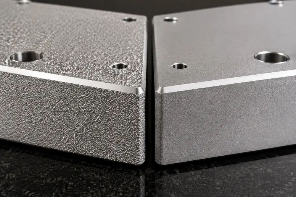
The mechanical pre-treatment chosen before chemical processing determines whether the final component displays an optical matte, satin, or semi-gloss appearance. Machining tool marks, step-over ridges from ball-nose end mills, and micro-burrs remain visible through anodic coatings unless systematically leveled through mechanical or chemical preparation. Achieving a uniform matte black anodized aluminum texture requires precise abrasive media calibration.
Abrasive Media Selection for Matte Finishes
To produce a uniform matte surface, abrasive blasting is the standard industrial approach. The choice of media directly impacts surface roughness, light diffusion, and fingerprint resistance. Engineers can evaluate these profiles against standardized surface roughness Ra conversion standards to establish repeatable drawing callouts:
1. Glass Beads (#8 to #10, 75 to 150 µm): Imparts a peened, satin sheen with low Ra (0.8 to 1.2 µm). Glass beads level minor cutter marks but offer low resistance to handling stains, as skin oils easily fill the micro-craters and produce dark, glossy smudges.
2. Ceramic Beads (Zirblast B60 / B120, 63 to 125 µm): High-density ceramic media creates an ultra-fine, uniform micro-dimpled surface (Ra 0.6 to 1.0 µm). This structure provides exceptional light diffusion with high resistance to burnishing, making it the industry standard for consumer electronics and medical optics.
3. White Fused Alumina (120 to 180 Mesh, 70 to 105 µm): Angular aluminum oxide cuts into the base material rather than peening it, producing a flat, non-reflective matte finish (Ra 1.6 to 2.4 µm). This texture eliminates directional glare in drone optical mounts and sensor chassis, though it feels coarser to the touch.
Surface Texture and Gloss Performance Matrix
|
Pre-Treatment Method |
Media / Grit Specification |
Surface Roughness (Ra) |
60° Gloss Units (GU) |
Tactile Feel |
CNC Tool Mark Concealment |
|
Coarse Bead Blast |
Glass Bead #8 (100 to 150 µm) |
1.4 to 2.0 µm |
5 to 10 (Matte) |
Textured Satin |
Hides heavy face-mill stepovers up to 0.05 mm |
|
Fine Ceramic Blast |
Zirblast B120 (63 to 125 µm) |
0.6 to 1.0 µm |
8 to 15 (Semi-Matte) |
Velvety Smooth |
Hides fine toolmarks on Ra 0.8 machined surfaces |
|
Aluminum Oxide |
Fused Al2O3 150 Mesh |
1.8 to 2.5 µm |
2 to 5 (Dead Flat) |
Dry / Chalky |
Conceals all cutter ridges, high light absorption |
|
Linear Graining |
Scotch-Brite / 240 Grit Belt |
0.4 to 0.8 µm |
25 to 45 (Satin) |
Directional Silk |
Accentuates longitudinal features, highlights edges |
|
Chemical Bright Dip |
Phosphoric / Nitric Bath |
0.2 to 0.4 µm |
70 to 90 (High Gloss) |
Mirror Slick |
Exposes all machining flaws; requires Ra under 0.2 base |
Etch Stock Loss Considerations
Caustic etching in hot sodium hydroxide cleans and micro-etches the aluminum prior to anodizing. Light decorative etching removes 2 to 4 µm of material, while heavy matte etching can remove 10 to 15 µm per surface. This metal removal must be factored into dimensional stack-ups, as excessive etching rapidly opens up reamed bore tolerances before the anodic layer is grown.
Wire EDM Recast Layers vs. Milled Surfaces
When manufacturing complex robotic linkages or aerospace manifolds, components often feature both multi-axis CNC milling operations and wire-cut electrical discharge machining profiles. A persistent manufacturing issue occurs when the finished component displays a rich, dense black on all milled surfaces, while the wire-EDM faces turn dull gray, develop uneven splotches, or suffer localized coating flaking.
This defect stems from the EDM recast white layer. Wire electrical discharge machining melts the aluminum alloy using rapid spark discharges, rapidly quenching it with deionized dielectric water. This thermal shock creates a brittle, non-uniform layer (typically 3 to 12 µm thick) loaded with altered alloy microstructures, thermal micro-cracks, and brass zinc contamination from the wire electrode.
This layer reacts unpredictably in sulfuric acid baths, yielding low pore density and poor dye absorption. Xiamen Dazao Machinery eliminates this failure by specifying a mechanical skiving pass or applying a dedicated chemical deoxidizing wash on all EDM cut surfaces, stripping the recast layer down to the undisturbed crystalline substrate prior to the anodizing rack.
Troubleshooting Color Variations and Fading in Black Anodized Aluminum
When parts show color defects during assembly, engineers often struggle to isolate chemical bath issues from mechanical root causes. Understanding why is black anodizing uneven requires analyzing dye chemistry, sealing integrity, and bath cleanliness.
Chemistry and Process Failure Modes
1. Chemical Bath Contamination
Sulfuric acid electrolytes must remain free from excessive dissolved solids. When dissolved aluminum concentrations climb past 20 g/L, or foreign heavy metal ions contaminate the tank, electrical conductivity fluctuates. This shifts current distribution across the tank, producing blotchy coverage and soft, under-oxidized zones.
2. Metamerism and Light Source Color Shifts
Components that appear deep black under 6500K inspection lamps may shift to a bronze, purple, or navy blue tone when placed under 3000K warm incandescent lighting or high-intensity retail spotlights. This optical shift, known as metamerism, occurs when organic black dyes rely on a blend of red, yellow, and blue dye molecules. If the blue or red component has an uneven absorption band, reflected light skews the perceived color under specific spectrums. Demanding outdoor or aerospace applications should specify inorganic metallic salts rather than organic dyes, establishing permanent UV-stable black pigmentation.
3. Premature Fading and Chemical Bleaching
The phenomenon of black anodized aluminum fading is typically caused by inadequate pore sealing. Unsealed or poorly sealed pores expose dye molecules to environmental moisture, solar ultraviolet radiation, and acidic cleaning agents, which rapidly break down the chemical chromophores.
Quality control protocols require either:
· High-Temperature Deionized Water Sealing (96°C to 100°C): Hydrolyzes aluminum oxide into boehmite, swelling the pore walls shut.
· Mid-Temperature Nickel Acetate Sealing (75°C to 85°C): Precipitates nickel hydroxide within the pore mouths, forming a stable chemical plug that blocks dye migration.
Capillary Bleeding from Blind Tapped Holes
A catastrophic failure mode in industrial hardware involves clean, visually perfect black components arriving at an assembly plant, only to develop powdery white crusts around blind tapped holes weeks later during ocean transit. This white bloom binds fasteners, damages delicate electronics, and strips threads during final assembly.
This defect is caused by entrapped sulfuric acid. During anodizing, aggressive acid electrolytes are forced deep into the bottoms of small, blind threaded holes. High surface tension prevents passive rinse tanks from clearing this fluid. During subsequent dye baths, the trapped acid leaches out through capillary action, bleaching away the black dye around the hole perimeter. Later, during shipping, the residual trapped acid continues reacting with the bare aluminum threads, corroding the base metal and depositing hydrous aluminum sulfate crystals.
At Xiamen Dazao Machinery, production standards prevent capillary weeping through a four-stage process:
1. Blind holes are blown out with clean, dry compressed air between active chemical tanks.
2. Parts undergo pressurized ultrasonic neutralization baths in a mild sodium bicarbonate solution.
3. Rinsing utilizes multi-stage counter-current hot deionized water tanks.
4. Finished parts pass through convection drying ovens operating at 65°C to vaporize all residual moisture from internal cavities before packaging.
CNC Design and Tolerance Specifications for Black Anodized Aluminum
Achieving tight assembly fits requires establishing explicit black anodizing specifications for CNC parts directly on production CAD models and 2D engineering drawings. Integrating robust design for manufacturing guidelines for aluminum parts prevents costly secondary tooling modifications.
Compensating Internal and External Thread Tolerances Before Anodizing
Because anodic coatings grow perpendicular to every exposed surface, 60-degree V-threads experience magnified dimensional shifts. Due to the geometry of the 60-degree thread flank angle, every unit of coating growth on the flank shifts the pitch diameter by four times that single-surface thickness.
· On a standard Type II specification with an 8 µm growth per face, external threads grow by 32 µm on the pitch diameter, while internal tapped holes shrink by 32 µm.
· For standard Class 6H internal threads smaller than M4, this reduction causes standard fasteners to bind or gall during assembly.
· Machinists executing high-precision CNC turning operations and milling must use oversize taps such as GH3 or GH5 limits, or program single-point thread paths with calibrated pitch diameter offsets to ensure class-of-fit compliance after final sealing.
Precision Bores and Bearing Fits
Bores machined to H7, H6, or press-fit dowel pin tolerances with total tolerance bands of 0.008 to 0.015 mm cannot reliably accept standard anodizing variations without functional failure:
· Option A: Pre-Anodize Masking: Silicone pull plugs, tapered EPDM stoppers, or custom-machined expandable fluoropolymer fixtures mask bores prior to chemistry. This preserves base-metal conductivity and raw machining tolerances, leaving the bore silver.
· Option B: Line Boring Post-Anodize: The component is anodized completely in black, returned to the machining center, and the precision bore is finish-machined with a carbide reamer or precision boring head. This provides exact bore roundness and nominal sizing, but exposes bare aluminum within the bore.
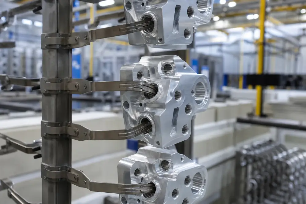
Rack Mark Placement
Anodizing requires a secure mechanical and electrical contact. Current flows through the mounting rack into the component via titanium or aluminum contact fingers. The contact point receives no anodic coating and leaves a small bare mark:
· Drawings must explicitly designate non-critical surfaces for racking, such as internal counterbores, blind threaded cavities, or back mounting faces.
· Clamping across cosmetic exterior surfaces, precision O-ring sealing lands, or dynamic sliding faces should be strictly prohibited on drawings.
Avoiding Air Trapping and Burning on Complex Geometries
· Corner Radii: Sharp external edges with radii below 0.2 mm concentrate electrical field lines in the anodizing tank, drawing excessive current density. This results in local burning, brittleness, and chipping along outer corners. Engineers should specify a minimum external edge radius of 0.5 mm or a 0.3 mm chamfer to ensure smooth coating growth.
· Air Trapping in Fluid Manifolds: Deep internal pockets, complex hydraulic channels, and blind cross-holes trap process air and hydrogen gas during tank immersion. Trapped gas bubbles displace the liquid acid, preventing coating formation and leaving raw, un-anodized bare spots inside the chamber. Cross-drilled vent passages or clear orientation callouts are necessary for manifold designs.
Engineering Drawing Callouts and Quality Inspection Standards for Black Anodizing
Ambiguous drawing notes such as finish anodize black invite severe quality discrepancies across vendor networks. Engineering documentation must define the governing military or international standard, coating classification, pre-treatment texture, thickness tolerances, and verification methods.
Standardized Drawing Callout Examples
Standard Decorative / Corrosion Callout (Type II)
Surface Finish: Anodize to MIL-A-8625F, Type II, Class 2 (Black). Pre-treatment: Fine ceramic bead blast (Zirblast B120, Ra 0.8 ± 0.2 µm). Coating thickness: 15 µm to 20 µm. Sealing: Nickel acetate seal. Dimensions apply AFTER surface treatment. Racking permitted only inside M6 tapped features.
Extreme Wear / Industrial Callout (Type III)
Surface Finish: Hardcoat Anodize to MIL-A-8625F, Type III, Class 2 (Black), non-dyed or inorganic dyed. Coating thickness: 50 µm ± 5 µm. Surface hardness: Minimum 500 HV. Sealing: Unsealed for maximum abrasion resistance or DI water sealed per purchase order requirement. Critical bearing bore diameter 25.000 +0.012/-0.000 mm must be masked free of coating.
Inspection and Quality Assurance Verification
Incoming Quality Control should verify conformance against defined physical and optical parameters through rigorous quality assurance and metrology protocols:
1. Coating Thickness Measurement (ASTM B244 / ISO 2360): Eddy-current coating thickness gauges verify depth across at least five distinct locations. Calibration must be performed against the bare base substrate of the same production heat lot to account for base material magnetic properties.
2. Seal Quality Verification (ASTM B136): A drop of 50% nitric acid is placed on the black surface for 2 minutes, rinsed with deionized water, followed by a drop of blue dye solution for 1 minute. If any blue stain remains after cleaning, the pore structure was improperly sealed, and the component will fail under field exposure.
3. Color and Gloss Consistency (CIELAB System): Visual color checks under inconsistent ambient light should be replaced with a calibrated spectrophotometer. In the CIELAB color space, lightness L must remain below 24.0, while color coordinates a and b must stay within plus or minus 0.5 of neutral zero. The total calculated color difference Delta E must remain below 1.5 across production batches to prevent visible assembly mismatches.
Factory Audit Red Flags for Procurement Teams
When evaluating external surface finishing partners, mechanical engineers and procurement officers should watch for these warning signs:
· Manual cycle timers and missing electronic ramp rectifiers.
· Tanks cooled by ambient shop air or tap water rather than industrial titanium heat-exchange chillers running tight PLC loops.
· Rinsing parts in municipal tap water instead of closed-loop deionized water systems with conductivity below 10 µS/cm.
· Finishing facilities lacking scheduled daily chemical titration records for free sulfuric acid, dissolved aluminum concentrations, and dye bath pH.
Precision Black Anodizing and CNC Manufacturing with Dazao
Predictable, uniform components require managing the relationship between CNC machining, metallurgy, and electrochemical processing. Cutting metal without calculating coating growth, or designing thin-walled parts without considering heat dissipation and electrical contact points, leads to dimensional rework and assembly rejections.
Xiamen Dazao Machinery eliminates quality variations by operating an integrated, ISO9001 and IATF16949-certified manufacturing facility. By combining advanced 5-axis CNC machining services with end-to-end surface finishing oversight, Dazao ensures every part matches your technical prints. Our engineering teams review CAD geometries to apply thread offsets, calculate bore shrinkages, optimize racking geometries, and verify color consistency across every delivery.

FAQs
01.Why does black anodized aluminum turn purple under sunlight?
02.How do you calculate CNC thread clearances for black anodizing?
03.Why do white powdery deposits bleed out from blind holes after shipping?
04.Can Al7075 achieve the exact same deep black color as Al6061?
05.What causes blotchy or uneven color on a single machined part?
06.How can electrical grounding be maintained on black anodized chassis?