


Selecting between aluminum and steel for precision CNC machining demands an analysis beyond raw material prices and basic tensile strength. While aluminum vs steel trade-offs often favor aluminum for rapid metal removal rates, a 3:1 strength-to-weight ratio advantage, and lower component mass, steel provides triple the elastic modulus (200 GPa vs 70 GPa), indefinite fatigue endurance limits, and superior structural rigidity. Substituting steel with aluminum without accounting for deflection formulas, differential thermal expansion (23 ppm/K vs 12 ppm/K), or galvanic thread seizure results in catastrophic mechanical assembly failures.
Aluminum vs Steel for CNC Machining: Engineering Selection and Cost Guide
When assessing aluminum vs steel for CNC machining, machine shops and mechanical design engineers often balance conflicting structural, manufacturing, and budgetary objectives. Selecting the wrong metal stock sets off a chain reaction across the bill of materials (BOM), altering spindle cycle times, cutting-tool life cycles, post-processing steps, and tight-tolerance field performance.

CNC Material Selection Reality: Engineering Risks and Shop-Floor Failures
Engineering textbooks often reduce the choice of aluminum or steel for machining to a linear strength-to-weight calculation. In real-world multi-axis CNC manufacturing, material behavior under high tool-engagement forces reveals sharp technical divides.
How Yield Strength Assumptions Caused a Cycloidal Gearbox Failure?
At the Dazao manufacturing plant, an early-stage medical robotics developer submitted a revision for an articulated robotic arm. In a bid to reduce motor payload, the design team replaced a pre-hardened AISI 4140 alloy steel transmission hub with Al7075-T6 aluminum. Reviewing the machining parameters and structural limits of 7075 aluminum before replacing alloy steels prevents costly elastic deflection failures, yet the initial engineering review overlooked this critical validation.
The design justification appeared solid on paper:
· Al7075-T6 yield strength: 503 MPa
· Normalized 4140 steel yield strength: 415 to 655 MPa
On paper, the 7075-T6 component cut mass by 65% while providing comparable static yield performance.
However, during dynamic cycle testing under continuous reversing torque, the internal cycloidal gearbox jammed at cycle 14,200. Diagnostic teardown at the Dazao inspection lab revealed two critical engineering oversights:
1. Cantilever Deflection: The transmission hub wall deflected elastically past allowable backlash limits under torsional peak loads, skewing gear engagement angles by 0.14 degrees.
2. Bearing Bore Relaxation: Frictional motor heat expanded the aluminum housing bore faster than the chrome steel bearing outer ring, causing radial clearance loss and destructive ball spalling.
The client lost four weeks of validation testing and incurred secondary tooling rework. This incident highlights a common failure mode: treating yield strength as an interchangeable metric while ignoring base physical constants like the modulus of elasticity and thermal coefficients.
Impact of Material Selection on Machine-Tool Allocation and Cycle Times
Evaluating aluminum vs steel for metal parts goes beyond raw billet costs. The selected stock dictates machine-tool asset allocation. High-speed aluminum milling demands high-RPM (12,000 to 24,000 RPM) dynamic centers with rapid chip-evacuation spirals. Hardened steel machining shifts jobs to rigid, box-way horizontal machining centers (HMCs) or heavy-duty vertical machining centers (VMCs) configured with high-torque geared spindles.
Your material choice impacts:
· Machining cycle time and spindle-hour billing rates
· Cutting-tool consumption curves (carbide grades, geometries, PVD and CVD coatings)
· Raw-material stock stability (residual stress release during pocket milling)
· In-line inspection frequency and secondary thermal soak times
Mechanical Property Comparison: Aluminum vs Steel for Metal Parts
Making an informed material decision requires examining physical mechanics under high-load engineering constraints.
Density, Mass Reduction, and Dynamic Inertia Calculations
When evaluating aluminum vs steel weight and aluminum vs steel density, the baseline figures show:
· Structural Aluminum (such as 6061-T6): 2.70 g/cm³ (0.0975 lb/in³)
· Medium Carbon and Alloy Steel (such as 1045, 4140): 7.85 g/cm³ (0.284 lb/in³)
This ratio of roughly 1 to 2.9 directly impacts dynamic inertia. In reciprocating automation equipment, high-speed pick-and-place gantries, and aerospace housings, lower mass reduces inertial resistance (J=m⋅r2). Utilizing lightweight automotive aluminum alloys in precision machining lowers dynamic inertia across high-performance suspension links and motor housings. Reducing moving mass by 65% lowers motor torque requirements, cuts kinetic energy dissipation during sudden stops, and reduces mechanical drive wear.
However, in heavy industrial equipment, base frames, and vibration-damping machine beds, high mass is an asset. The added bulk of steel increases mechanical stability, anchors high-torque assemblies, and lowers center-of-gravity profiles.
Yield Strength vs Cyclic Fatigue: The S-N Curve Disparity
When analyzing aluminum vs steel strength, engineers must separate static yield from cyclic fatigue behavior:
|
Material Grade |
Density (g/cm3) |
Tensile Yield Strength (MPa) |
Ultimate Tensile Strength (MPa) |
Elastic Modulus (GPa) |
Brinell Hardness (HBW) |
|
Al6061-T6 |
2.70 |
276 |
310 |
68.9 |
95 |
|
Al7075-T6 |
2.81 |
503 |
572 |
71.7 |
150 |
|
AISI 1018 Steel |
7.87 |
370 |
440 |
205 |
126 |
|
AISI 4140 (Q&T at 425°C) |
7.85 |
950 |
1020 |
210 |
302 |
|
304 Stainless Steel |
8.00 |
215 |
505 |
193 |
170 |
While aluminum vs steel strength to weight ratio highlights alloys like Al7075-T6 exceeding low-carbon steels, cyclic fatigue remains a critical engineering differentiator.
The S-N Curve Reality
Ferrous alloys exhibit an endurance limit (Se). If dynamic cyclic stress stays below roughly 40% to 50% of its ultimate tensile strength, structural steel can endure infinite load cycles without micro-crack propagation:
σcyclic < Se ⟹ N > 107 cycles without structural failure
Aluminum alloys possess no true fatigue limit. The stress-life (S−N) curve for aluminum continuously slopes downward. Even under low cyclic stresses, microstructural shear slip bands gradually develop into microscopic fatigue cracks:
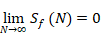
For parts subject to billions of load oscillations, such as rotating high-pressure pump shafts, heavy-duty springs, and press dies, aluminum guarantees eventual mechanical fatigue failure regardless of design yield allowances.
Modulus of Elasticity: Preventing Cantilever Deflection and Dynamic Resonance
The most frequent mistake in steel vs aluminum CNC machining conversions is confusing strength with stiffness. Evaluating aluminum vs steel stiffness proves that alloy formulation cannot overcome natural atomic bonds:
· All commercial aluminum alloys exhibit an Elastic Modulus (E) of 68 to 72 GPa.
· All carbon, tool, and structural alloy steels exhibit an Elastic Modulus (E) of 190 to 215 GPa.
Heat treatment, cold working, or high-end alloying (such as Al-Zn-Mg-Cu matrices) cannot significantly alter this physical constant. Steel is fundamentally three times stiffer than aluminum.
Consider a simple cantilever beam of length L, subject to a concentrated end load P. Linear beam deflection (δ) is governed by:

Where:
· E is the modulus of elasticity
· I is the Area Moment of Inertia (I=bh312 for a rectangular section)
To match the structural deflection of a steel beam without altering beam width (b), an aluminum component must increase its thickness (h) by:

To compensate for stiffness losses, the aluminum wall must be made 43% thicker. Following practical design rules for CNC machined aluminum components allows engineering teams to increase wall thickness without compromising weight targets. If geometric envelope constraints prevent increasing cross-sectional geometry, replacing steel with aluminum will cause your assembly to flex, chatter, and run out of true under normal operational loads.
Hidden Engineering Bottlenecks: Dazao Machining and Assembly Insights
Standard industry articles rarely discuss the assembly, thermal, and interface challenges encountered when running tight-tolerance CNC production. At Dazao, our quality assurance and milling teams routinely solve these three engineering bottlenecks.

Differential Thermal Expansion: Preventing Bearing Fit Relaxation
A common challenge in precision CNC operations is managing the Coefficient of Thermal Expansion (CTE):
· Aluminum: α≈23.0×10⁻⁶ / K (at 20°C)
· Carbon and Alloy Steel: α≈11.5 to 12.2×10⁻⁶ / K (at 20°C)
· 52100 Bearing Steel: α≈11.9×10⁻⁶ / K
Aluminum shifts dimensionally at roughly twice the rate of steel when exposed to temperature gradients.
The Real-World Engineering Problem
Consider a spindle bearing housing requiring a ∅50.000 mm (+0.005/−0.000 mm) bore holding an ISO P4 class angular contact steel bearing.
The part is machined, inspected, and verified on a CMM in the climate-controlled inspection room at Dazao at 20°C (68°F).
Once deployed into an operating environment without active liquid cooling, the assembly equilibrium temperature rises to 55°C (ΔT=35 K):
ΔDAl=D0⋅αAl⋅ΔT=50.000×(23.0×10−6)×35=+0.04025 mm
ΔDSteel=D0⋅αSteel⋅ΔT=50.000×(11.9×10−6)×35=+0.02082 mm
ΔGap=ΔDAl−ΔDSteel=0.04025−0.02082=+0.01943 mm (≈19.4 μm)
An interference press fit calculated at +0.005 mm at room temperature transitions into a loose fit with 14.4 microns of radial play at operating temperatures.
The steel bearing will walk, vibrate within the aluminum bore, generate fretting corrosion, and cause premature spindle runout. When combining steel and aluminum in high-precision assemblies, engineers must calculate thermal drift margins and consider cast-iron liners, bronze bushings, or dedicated retaining rings.

Thread Stripping, Helicoil Installation Costs, and Galvanic Corrosion
Tapping threads into structural aluminum is fast, but bare internal aluminum threads fail under harsh operating conditions.
· Fastener Torque Degradation Mechanism: Repeated torque cycles on an M6x1.0 internal thread in aluminum cause micro-galling by cycle 5, progressing to complete flank shear by cycle 12.
· The Dazao Shop-Floor Corrective Measure: Machine the base hole, perform single-point STI thread tapping, drive a 304 stainless steel Helicoil or solid key-locking insert, and perform final go/no-go plug gage inspection.
· Shear and Galling: Direct threading into 6061-T6 works for static access covers. However, for maintenance panels or mounting brackets subject to repeated torque cycles, internal aluminum threads gall and strip out under moderate preload.
· The True Production Cost: Converting threaded holes in aluminum to industrial standards requires manual or semi-automated thread inserts (such as Helicoils, Keenserts, or PEM studs). On a gearbox casing with 48 tapped holes, purchasing inserts, cutting special STI class threads, and installing them manually adds $0.80 to $2.20 per hole in labor and overhead. This added step can wipe out the raw machining cost savings of choosing aluminum.
· Galvanic Corrosion: When stainless steel bolts seat into bare aluminum in the presence of an electrolyte (like humidity or coolant mist), the large difference in electrochemical potential (ΔV>0.60 V) triggers galvanic action. Aluminum acts as a sacrificial anode, oxidizing into a white powder that locks the steel fastener into place. Preventing this requires hard-anodizing the aluminum, applying zinc-nickel plating to fasteners, or adding anti-seize paste during assembly.
Machine Rigidity: Matching High-Speed Spindles vs High-Torque Gearboxes
Machinists know that aluminum vs steel for CNC machining demands entirely different machine-tool capabilities. Utilizing dedicated, high-rigidity CNC milling services ensures that machine-tool frames correspond directly to material cutting forces:
· Aluminum Dynamics: Demands high cutting speeds (Vc>600 m/min) and high spindle RPM (>15,000 RPM) paired with low-torque, high-acceleration feed motions. The primary goal is moving chips out of the pocket before heat transfers into the workpiece.
· Alloy Steel Dynamics: Requires high spindle torque at low speeds (Vc=90 to 180 m/min, spindle RPM between 800 and 3,500 RPM) driven by geared spindles or heavy-duty BT50 tapers, backed by high-rigidity Meehanite cast-iron machine beds.
Attempting to run pre-hardened 4140 steel or 316 stainless steel on an agile, high-speed BT30 or light-duty BT40 linear-guide machine causes cutting chatter. The machine structure lacks the static mass to damp tool-engagement harmonics. This causes broken carbide inserts, wavy surface finishes (Ra>3.2 μm), and rapid spindle bearing wear.
Conversely, routing large aluminum billets through heavy, slow-moving bridge mills runs up excessive cycle times, increasing the part unit cost. Matching material to machine-tool dynamics is critical to achieving stable tolerances and competitive per-piece pricing.
CNC Machinability: Cutting Speed, Tool Wear, and Heat Dissipation
The operational distinction between aluminum vs steel machinability shapes daily production schedules, tooling budgets, and machine setup strategies across modern machine shops.

Metal Removal Rates (MRR), Chip Formation, and Built-Up Edge Control
When calculating aluminum vs steel cutting speed, the Metal Removal Rate (MRR) dictates overall machine cycle time:
MRR=ap⋅ ae⋅ vf
Where:
· ap is axial depth of cut (mm)
· ae is radial width of cut (mm)
· vf is table feed speed (mm/min), where vf=n⋅z⋅fz
Leveraging specialized high-speed aluminum CNC milling methodologies allows production lines to hit surface speeds exceeding 1,200 meters per minute. The differences in cutting metrics between structural aluminum and pre-hardened alloy steel are stark:
|
Cutting Parameter |
Al6061-T6 (Uncoated Solid Carbide) |
AISI 4140 Annealed (TiAlN Coated Carbide) |
304 Stainless Steel (AlCrN Coated Carbide) |
|
Surface Speed (Vc, m/min) |
600 to 1800+ |
120 to 220 |
80 to 140 |
|
Feed per Tooth (fz, mm/tooth) |
0.10 to 0.35 |
0.06 to 0.15 |
0.04 to 0.10 |
|
Volumetric MRR Index |
Base 100% (High Velocity) |
18% to 28% of Aluminum |
10% to 16% of Aluminum |
|
Chip Evacuation Style |
Continuous ribbon / High-volume spiral |
Tight dynamic curls (6-shape) |
Tough, stringy, work-hardening ribbons |
|
Coolant Requirement |
Flood mist or MQL (Anti-adhesion) |
High-pressure flood (Chip clearing) |
High-pressure through-spindle (Damping) |
Aluminum machining prioritizes raw cutting speed and clearance. The main engineering challenge is avoiding Built-Up Edge (BUE). Aluminum can weld itself to carbide tool cutting edges via micro-galling if local temperatures spike. Machinists counter this by using balanced tool holders, 2- or 3-flute end mills with mirror-polished deep flutes, high rake angles, and specialized coatings like Zirconium Nitride (ZrN) or diamond-like carbon (DLC).
Steel machining demands strict thermal and chip-break control. Tool paths must manage engagement angles through trochoidal milling or dynamic adaptive clearing. This practice limits tool-to-workpiece contact arcs, protecting cutting edges from cyclic thermal shock and premature micro-chipping.
Thermal Conductivity and Carbide Tool Wear Patterns
Heat dissipation mechanics highlight another fundamental divergence in aluminum vs steel heat dissipation and aluminum vs steel tool wear:
· Thermal Conductivity of Al6061: Approximately 167 W/m·K
· Thermal Conductivity of AISI 4140: Approximately 42.6 W/m·K
· Thermal Conductivity of 304 Stainless: Approximately 16.2 W/m·K
Because aluminum conducts heat four times faster than carbon steel and ten times faster than austenitic stainless steel, the chips carry away roughly 75% to 85% of cutting-zone friction heat. The workpiece remains dimensionally stable throughout aggressive roughing routines.
Thermal Energy Distribution During Tool-Chip Contact:
· In aluminum milling: 80% of shear zone heat leaves with chips, 15% dissipates into the part body, and 5% enters the cutting tool.
· In alloy steel milling: 50% of shear zone heat leaves with chips, 25% enters the part body, and 25% concentrates in the cutting tool, requiring advanced PVD thermal barriers.
When cutting hardened alloy steels or nickel-bearing stainless grades, thermal energy concentrates directly at the cutting edge. Tool tips can experience localized temperatures above 800°C.
At the Dazao facility, tool-life records indicate that milling pre-hardened 4140 steel (32 HRC) consumes solid-carbide cutting edges 6 to 9 times faster per cubic centimeter of removed metal than milling 6061-T6. Frequent insert indexing, tool wear offsets, and touch-off cycles increase operator runtime requirements and overall production costs on steel components.
Surface Finish Quality and Relieving Residual Internal Stresses
Assessing aluminum vs steel surface finish reveals distinct shop-floor parameters:
· Aluminum: Yields high-gloss finishes (Ra≤0.4 μm) using diamond inserts or ground carbide balance tools at high spindle speeds. However, large billet hog-outs can warp significantly. Removing large volumes of material upsets internal stress distributions, leading to component bowing. Machinists must specify stress-relieved T651 plate stock (stretched mechanically after solution heat treatment) and use progressive roughing passes across alternate faces to maintain flat profiles.
· Steel: Delivers exceptional dimensional stability on bearing journals, precision ground seal faces, and sliding guideways (Ra≤0.2 μm through hard-turning or cylindrical grinding). Applying multi-axis CNC turning capabilities to pre-hardened alloy shafts achieves tight bearing journals without secondary cylindrical OD grinding. Cold-drawn steel bars contain considerable peripheral residual tensile stresses. Opening deep keyways or cutting unilateral slots into cold-drawn 1018 stock causes visible bowing unless the stock is stress-relief annealed prior to final machining passes.
Alloy Grade Selection Guide: Comparing 6061, 7075, 4140, and Stainless
Evaluating aluminum or steel for machining requires comparing specific engineering alloys rather than making generic material assumptions across broad aluminum vs steel applications.

Precision Aluminum Alloys: Properties of 6061-T6, 7075-T6, 5052, and 2024
When evaluating the best aluminum alloys for precision CNC machining, engineers must balance tensile performance against machinability and cost:
· Al6061-T6: The default alloy for structural precision components. As detailed in our technical guide to 6061 aluminum CNC machining, this temper provides balanced mechanical stability for structural frameworks, fluid blocks, and electronics enclosures.
· Al7075-T6: A high-strength zinc-copper alloy providing structural yield characteristics comparable to low-carbon steels. It is standard for high-performance components like racecar uprights, aerospace pivot brackets, and drone structural spars. Its trade-offs include lower corrosion resistance and difficult anodizing color matching.
· Al5052-H32: A non-heat-treatable alloy common in sheet-plate assemblies, marine housings, and deep-drawn structures requiring superior marine-spray resistance. It is gummy during CNC milling operations and requires sharp shear tooling.
· Al2024-T351: Adhering to certified aerospace aluminum CNC machining standards ensures tight grain boundary integrity across high-stress flight components. 2024 exhibits high fracture toughness and resistance to cyclic crack growth, though it offers poor weldability and lower galvanic corrosion resistance than 6000-series grades.
Structural and Alloy Steels: Machining 1018, 4140, 304, and 17-4 PH
· AISI 1018 / 1045: Workhorse low-to-medium carbon steels. 1018 is ideal for case-hardened, carburized components and weldments. 1045 provides higher as-machined tensile strength for pivot pins, unhardened gear blanks, and basic machinery mounting plates.
· AISI 4140 (Chromoly): Chromium-molybdenum steel supplied either annealed or pre-hardened (28 to 32 HRC). It is the baseline standard for structural spindles, heavy load shafts, motor drive couplers, and downhole hydraulic assemblies requiring high core toughness.
· AISI 304 / 316 Austenitic Stainless: The global standard for food-grade, pharmaceutical, and marine fluid systems. They offer excellent chemical and pitting resistance. However, strong work-hardening characteristics demand rigid tool setups, positive rake geometries, and uninterrupted feeds to prevent the tool from rubbing and burnishing.
· 17-4 PH (AISI 630): A precipitation-hardening martensitic stainless steel. It machines efficiently in the Condition A annealed state and can be hardened up to 44 HRC via simple, single-step low-temperature aging (H900), avoiding the severe quench distortion typical of conventional steels.
Surface Finishing and Corrosion Resistance: Plating, Anodizing, and Tolerances

Anodizing vs Plating: Coating Hardness and Wear Protection
When reviewing aluminum vs steel corrosion resistance and aluminum vs steel durability, machined parts must resist wear, friction, and environmental oxidation throughout their service life. Consulting our comprehensive aluminum surface finishing reference guide enables designers to calculate accurate post-plate thread engagement limits and wear resistance:
|
Material Family |
Common Surface Treatment |
Layer Thickness (μm) |
Surface Hardness |
Primary Engineering Purpose |
|
Aluminum |
Type II Anodizing (Sulfuric) |
8 to 15 |
300 to 400 HV |
Aesthetic color options, basic barrier protection |
|
Aluminum |
Type III Hardcoat Anodizing |
25 to 50 |
450 to 550 HV |
High dielectric strength, abrasion resistance |
|
Aluminum |
Chem Film (Chromate / SurTec 650) |
0.1 to 0.5 |
Minimal base shift |
Electrical conductivity, corrosion-resistant primer |
|
Carbon/Alloy Steel |
Black Oxide (MIL-DTL-13924) |
0.5 to 1.5 |
Negligible change |
Decorative black finish; minimal corrosion resistance |
|
Carbon/Alloy Steel |
QPQ Salt Bath Ferritic Nitrocarburizing |
10 to 25 |
900 to 1200 HV |
Extreme sliding-wear endurance, salt-spray resistance |
|
Carbon/Alloy Steel |
Electroless Nickel Plating (ENP) |
5 to 50 |
500 to 1000 HV (baked) |
Uniform coverage, chemical and pitting defense |
|
Stainless Steel |
Chemical Passivation (Citric / Nitric) |
Molecular scale |
Unchanged |
Restores passive chromium oxide surface layer |
Tolerance Stack-up: Calculating Dimensional Growth from Surface Coatings
One critical cost driver in precision CNC manufacturing is managing post-treatment dimensional changes.
Type III Hardcoat Anodizing on aluminum penetrates into the base substrate by 50% and builds outward by 50%. A specified 40 μm coating adds approximately 20 μm of thickness per surface. This increases outer diameters by 40 μm and reduces interior bearing diameters by 40 μm. Unless engineers account for these dimensional shifts on manufacturing drawings, close-tolerance features will fall out of compliance.
Similarly, QPQ liquid nitriding on alloy steel alters dimensional profiles and involves high process temperatures (around 560°C). This heat can cause geometric distortion in thin-walled shells. The parts may require secondary post-treatment finish grinding or hone dressing to true up critical surfaces.
Total Manufacturing Cost Analysis: Material Price vs Machining Cycle Time
A common purchasing mistake when evaluating aluminum vs steel machining cost and aluminum vs steel manufacturing cost is looking solely at raw material costs per kilogram or pound. Manufacturing decision-makers must evaluate total manufacturing cost per piece (Ctotal):
Ctotal=Craw+(Tcycle⋅Rspindle)+Ctooling+Cfinish+Chardware
Where:
· Craw: Gross stock envelope cost less scrap salvage value
· Tcycle: Spindle cutting, positioning, and part-handling cycle time
· Rspindle: Blended machine-hour billing rate
· Ctooling: Dedicated cutting-tool wear and replacement allocation per component
· Cfinish: Surface plating, conversion coating, masking, and baking fees
· Chardware: Secondary thread reinforcements, inserts, and installation labor
Production Cost Comparison: 250-Piece Hydraulic Manifold Batch
Benchmarking project budgets against our CNC aluminum machining cost reduction breakdown demonstrates how high chip-removal rates offset higher raw material prices. Consider a batch run of 250 precision manifold blocks (finished envelope: 120 mm×80 mm×60 mm, with 65% material removed by volume):
Estimated Per-Unit Cost Breakdown for a Batch of 250 pieces based on Dazao tracking metrics:
Component Option A: Al6061-T6 with Type II Clear Anodizing
· Raw Billet Stock (2.7 kg gross): $14.50
· 4-Axis CNC Spindle Time (14.2 minutes at $65/hr rate): $15.38
· Tooling Wear and Consumables Allowance: $1.80
· Type II Anodizing (Bulk processing): $3.50
· Thread Inserts (12 stainless steel helicoils plus labor): $7.20
· Scrap Value Rebate: -$1.80
· TOTAL COST PER PIECE (ALUMINUM): $40.58
Component Option B: AISI 1018 Steel with Electroless Nickel Plating
· Raw Billet Stock (7.9 kg gross): $12.80
· 4-Axis CNC Spindle Time (38.5 minutes at $65/hr rate): $41.70
· Tooling Wear and Consumables Allowance: $6.20
· Electroless Nickel Plating (25 microns uniform): $8.40
· Thread Inserts: $0.00 (Threads tapped directly into base steel)
· Scrap Value Rebate: -$0.90
· TOTAL COST PER PIECE (STEEL): $68.20
Despite the higher raw stock cost of aluminum over plain low-carbon steel, the aluminum manifold delivers a 40.5% lower total piece cost. Shorter machine cycle times, reduced tool wear, and efficient bulk anodizing outweigh raw material expenses.
Conversely, for low-volume parts requiring minimal pocketing, high structural rigidity, direct thread durability, or extreme core hardness, steel remains the more cost-effective choice. It eliminates the need for expensive secondary thread inserts and specialty coatings.
Decision Matrix and DFM Engineering Checklist for RFQ Submission
Rapid Engineering Selection Flowchart: Aluminum vs Steel
Use this direct reference guide to confirm material selection during design stages:
1. Flowchart Selection Logic:
· Step 1: Is mass reduction critical to assembly performance for aerospace, robotics, or high-speed gantries?
· If YES: Check whether bearing fits are subject to operational thermal differentials greater than 35°C. If YES, use a pressed steel sleeve inside an aluminum housing or an all-steel hub. If NO, select Al6061-T6 or Al7075-T6.
· If NO: Does the part require high sliding wear resistance or surface contact hardness for gears, shafts, or guideways?
· If YES: Select AISI 4140 pre-hardened or case-hardened alloy steel.
· If NO: Is the component exposed to marine environments or chemical washdown? If YES, choose 316 stainless steel or hard-anodized aluminum. If NO, specify 1018 or 1045 steel with QPQ salt bath nitrocarburizing.
2. Summary Rules:
Select Aluminum when:
· Minimizing mass directly increases payload, battery endurance, or motion speed.
· Internal thermal transfer or heatsink fin cooling is required.
· Parts require decorative, corrosion-resistant anodized color options.
· High-volume material pocketing would cause prohibitive spindle times on steel.
3. Select Steel when:
· Structural deflection under bending, cantilever, or torsional load must be minimized within a tight geometric envelope.
· Components experience cyclic loads past 107 cycles, requiring an indefinite fatigue life.
· Mated components need surface hardness above 50 HRC to prevent sliding wear or galling.
· Assembly tolerances must track steel bearings across wide operational temperature swings.
Five Technical Drawing Validations Before Requesting a Machining Quote
Review these shop-floor checks before submitting CAD files to Dazao engineers:
1. Thermal Growth and Bore Specs: If mounting bearing steel races inside aluminum housings, confirm interference limits across the full operating temperature range.
2. Thread Engagement and Inserts: If a tapped aluminum thread will experience regular maintenance or high torque, design the hole to accept standard Helicoil or Keensert inserts.
3. Internal Radii and Corner Tooling: Avoid sharp internal pocket corners. Specify corner radii (R≥ pocket depth) to prevent cutter chatter and permit large-diameter roughing end mills.
4. Stock Temper and Stress Relief: Specify 6061-T651 or 7075-T6511 for pocket-milled aluminum plates, and call for normalized or stress-relieved bar stock for steel shafts.
5. Clear Finish Callouts: Clearly indicate whether drawing dimensions apply before or after surface finishing (such as Type III hardcoat anodizing or QPQ nitriding).
Submitting drawings for a professional DFM drawing review before cutting metal ensures complete dimensional stability and eliminates machining bottlenecks early.

FAQs
01.How do temperature swings affect steel bearing fits in aluminum housings?
02.Why should design engineers avoid tapping fine threads directly into 6061 aluminum?
03.Can high-strength 7075-T6 aluminum match the deflection resistance of 4140 steel?
04.How do you prevent stainless steel fasteners from seizing in CNC machined aluminum?
05.Why does milling alloy steel cause chatter on light-duty CNC machine centers?
06.How should CAD drawings account for Type III hard anodizing thickness?





