


Select 6061-T6 aluminum for high-load structural CNC components requiring superior tensile strength (310 MPa), high yield strength (276 MPa), tight dimensional tolerances(±0.01 mm), and predictable, segmented chip formation during high-speed milling.
Select 6063-T6 aluminum when parts require complex hollow extrusion geometries with secondary light CNC finishing, superior cosmetic anodizing uniformity, and a polished surface finish (Ra < 0.4 µm) for architectural, optical, or consumer electronic enclosures.
6061 vs 6063 Aluminum: Quick Selection Matrix for CNC Machinists
In precision CNC manufacturing, selecting between 6061 vs 6063 aluminum represents a fundamental trade-off between structural mechanical performance and geometric extrusion capability. When evaluating the best aluminum for CNC machining projects, mechanical design engineers, procurement specialists, and project managers frequently analyze 6061 vs 6063 for CNC machining to balance raw stock costs, machining cycle times, and post-processing aesthetics.
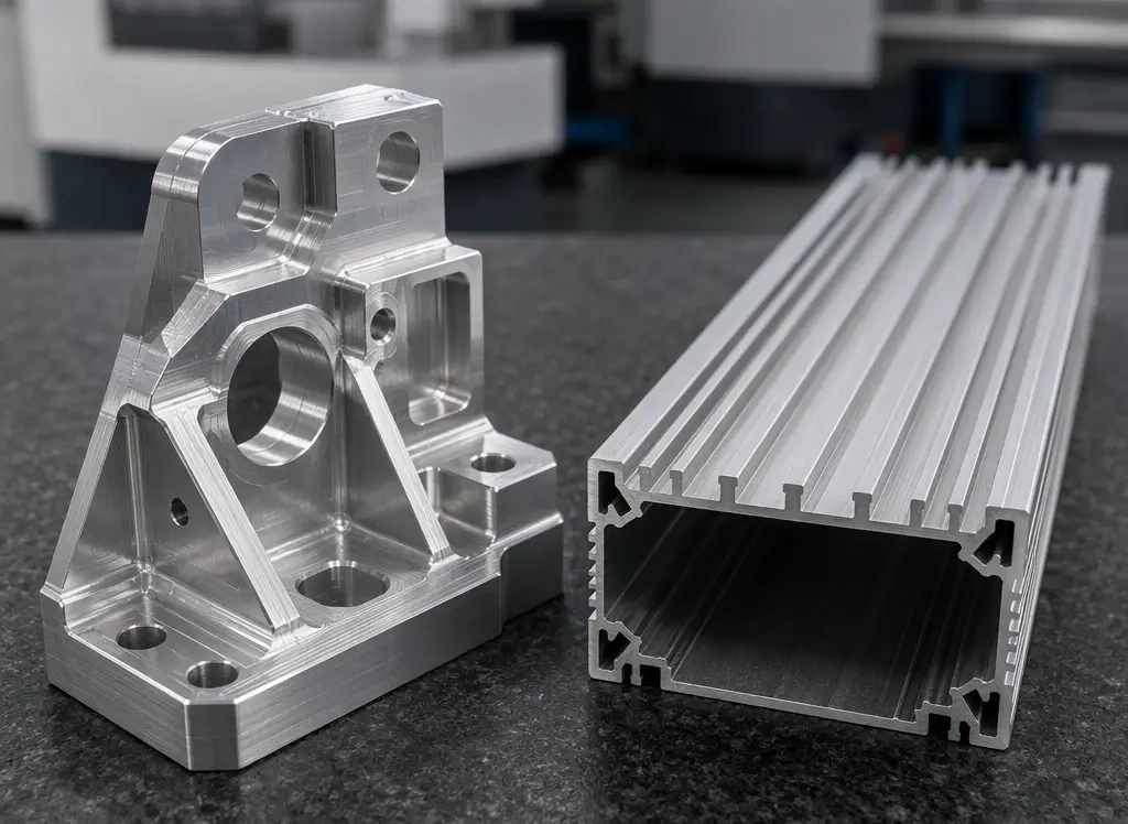
At the Dazao manufacturing plant, operating 5-axis machining centers and high-speed CNC turning cells under ISO9001:2015 and IATF16949:2016 quality systems, our baseline rule is absolute: 6061 aluminum alloy is the standard workhorse for high-load 6061 structural aluminum components, whereas 6063 aluminum alloy is an extrusion alloy optimized for complex hollow profiles requiring secondary milling, drilling, and decorative finishing.
Choosing between 6061 or 6063 aluminum requires evaluating the raw material delivery format (solid billet, plate, or custom aluminum extrusion for CNC machining), the total material removal volume, and the final mechanical environment.
Chemical Composition & Microstructure: Why 6061 and 6063 Cut Differently
The physical and mechanical divergence between 6061 aluminum properties and 6063 aluminum properties originates in their chemical alloying thresholds, governed by ASTM B221 and AMS-QQ-A-200 standards. Both belong to the magnesium-silicon (Al-Mg-Si) 6000-series family, but their alloying ratios govern their phase precipitation behavior during artificial aging.
|
Element (Weight %) |
6061 Composition Limit |
6063 Composition Limit |
Engineering Impact on CNC Machining & Processing |
|
Silicon (Si) |
0.40 to 0.80 |
0.20 to 0.60 |
Forms hardening precipitate phase; excess Si increases tool abrasion. |
|
Magnesium (Mg) |
0.80 to 1.20 |
0.45 to 0.90 |
Combines with Si to form beta-phase hardening precipitate; drives yield strength. |
|
Iron (Fe) |
Max 0.70 |
Max 0.35 |
Impurity; kept low in 6063 to prevent intermetallic grain boundary flaws. |
|
Copper (Cu) |
0.15 to 0.40 |
Max 0.10 |
Increases matrix shear strength in 6061; degrades anodizing clarity. |
|
Chromium (Cr) |
0.04 to 0.35 |
Max 0.10 |
Suppresses recrystallization, refines grain size, prevents stress corrosion. |
|
Zinc (Zn) |
Max 0.25 |
Max 0.10 |
Trace element; strictly capped to prevent galvanic micro-pitting. |
|
Titanium (Ti) |
Max 0.15 |
Max 0.10 |
Grain refiner added during billet casting. |
|
Manganese (Mn) |
Max 0.15 |
Max 0.10 |
Solid-solution strengthener; enhances elevated-temperature performance. |
|
Aluminum (Al) |
Balance (95.8 to 98.6) |
Balance (97.5 to 99.3) |
Higher base purity in 6063 yields higher ductility and metal flow rates. |
Precipitation Hardening and Dislocation Pinning in Al-Mg-Si Alloys
The mechanical integrity of 6061-T6 vs 6063-T6 is controlled by the stoichiometric precipitation of the magnesium silicide phase during artificial precipitation heat treatment (aging at 160°C to 180°C for 6 to 10 hours).
· The 6061 Matrix: The deliberate inclusion of copper (up to 0.40% Cu) and chromium (up to 0.35% Cr) in 6061 aluminum introduces complex quaternary dispersoids. These intermetallics pin dislocation movement across grain boundaries, increasing the 6061 yield strength to 276 MPa while providing clean micro-shear planes during milling tool engagement.
· The 6063 Matrix: With magnesium restricted to 0.45-0.90% and copper capped at 0.10%, 6063 aluminum profile stock contains a lower volume fraction of strengthening precipitates. The resulting matrix exhibits low resistance to plastic flow, making 6063 extrusion speeds up to 3 times faster than 6061 through multi-cavity dies, but yielding a softer metal that behaves differently under cutting inserts.
Mechanical Properties & Machinability: 6061-T6 vs 6063-T6 Comparison
When evaluating 6061 vs 6063 strength and cutting parameters for high-precision 6061 CNC parts versus 6063 CNC parts, quantifiable mechanical values dictate feed rates, spindle speeds, depth of cut, and expected tool life.
|
Mechanical Property |
6061-T6 (Milled Billet/Plate) |
6063-T6 (Extruded & Aged Profile) |
Testing Standard / Method |
|
Ultimate Tensile Strength (UTS) |
310 MPa (45,000 psi) |
241 MPa (35,000 psi) |
ASTM B557 |
|
Yield Strength (0.2% Offset) |
276 MPa (40,000 psi) |
214 MPa (31,000 psi) |
ASTM B557 |
|
Elongation at Break (%) |
12% to 17% |
12% to 18% |
50mm gauge length |
|
Brinell Hardness (HB500) |
95 HB |
73 HB |
10mm ball, 500kg load |
|
Shear Strength |
207 MPa (30,000 psi) |
152 MPa (22,000 psi) |
ASTM B565 |
|
Fatigue Endurance Limit |
96.5 MPa (5×10⁸ cycles) |
68.9 MPa (5×10⁸ cycles) |
R.R. Moore reverse bending |
|
Modulus of Elasticity (E) |
68.9 GPa |
68.3 GPa |
Tensile dynamic test |
|
Thermal Conductivity |
167 W/m·K |
201 W/m·K |
ASTM E1461 |
|
Machinability Index Rating |
70% (Free-cutting reference) |
55% (Prone to gummy buildup) |
Relative to 2011-T3 (100%) |
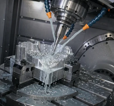
Chip Evacuation, Built-Up Edge (BUE), and Surface Finish (Ra) Analysis
1. Chip Formation and Shear Band Mechanics
· 6061 Machinability: The higher hardness (95 HB) and presence of secondary phase precipitates allow solid carbide cutting tools to produce crisp, segmented chips. The shear angle remains consistent across surface cutting speeds (Vc) ranging from 300 m/min to 1200 m/min, preventing long chip nests from damaging internal bores or wrapping around automatic tool changers. For deep programming insights, review our advanced 6061 aluminum CNC machining parameters and tooling guidelines.
· 6063 Machinability: Because of lower hardness (73 HB) and high base purity, 6063 machinability is compromised by material plasticity. Cutting tools induce plastic deformation ahead of the tool rake face rather than immediate shear rupture. This creates continuous ribbon chips that tangle around spindles and score finished walls unless high-pressure through-spindle coolant (minimum 20 bar) is deployed.
2. Built-Up Edge (BUE) Formation and Tool Tribology
When executing heavy milling or profiling on 6063 extrusion alloy, the low melting-point boundary phases generate localized adhesion on uncoated tungsten carbide tools:
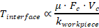
Where:
Tinterface = Cutting tool-chip interface temperature
μ = Friction coefficient between tool coating and aluminum
Fc = Main cutting force (N)
Vc = Surface cutting speed (m/min)
kworkpiece = Workpiece thermal conductivity (W/m·K)
Because 6063 has a high thermal conductivity (201 W/m·K) but low shear hardness, material transfer occurs rapidly at the tool tip under dry or low-lubrication conditions. This Built-Up Edge (BUE) increases effective tool radius, degrading part tolerances from ±0.01 mm to over ±0.05 mm.
Machining 6061-T6 produces significantly lower adhesive friction at identical surface speeds, maintaining tool edge sharpness for over 150 hours of continuous cutting when utilizing DLC(Diamond-Like Carbon) or micro-polished ZrN-coated solid carbide endmills.
3.Achievable As-Machined Surface Roughness (Ra)
· 6061 Surface Finish: Milled floor and wall surfaces regularly achieve Ra 0.8 µm (32 µin) under standard high-feed conditions, and Ra 0.4 µm (16 µin) using specialized finishing wiper geometry inserts with an axial depth of cut (ap) of 0.1 mm.
· 6063 Surface Finish: Direct face milling frequently suffers from micro-tearing on finished faces, yielding baseline surface finishes around Ra 1.6 µm to Ra 2.2 µm. Achieving a smooth 6063 surface finish requires high spindle speeds (N>15,000 RPM), reduced chip load (fz<0.04 mm/tooth), and continuous mist lubrication to prevent tearing along the crystal boundaries.
CNC Machining Blind Spots: 3 Real Shop Floor Failures and Engineering Solutions
Engineering datasheets provide nominal tensile and yield values, but they do not reflect what happens when high-speed cutting tools engage raw stock on a 5-axis machining center. Over 24 years of manufacturing custom components at Dazao, our engineering team has documented failure modes that standard alloy selection guides overlook.
Case 1: Residual Stress Warping in Thin-Walled 6063 Extrusion Milling
The Failure Scenario
A robotics client supplied custom 6063-T6 aluminum profile extrusions measuring 400 mm in length, 80 mm in width, and 40 mm in height with a 4 mm nominal wall thickness. The manufacturing drawing required single-sided CNC pocketing to create mounting windows and weight-reduction cavities, with a global planarity tolerance of ±0.05 mm.
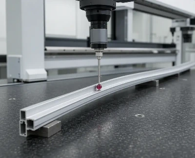
When the parts were unclamped from standard hydraulic vises following rough milling, every single component exhibited upward bow deflection along the longitudinal axis, with peak distortion measuring 0.82 mm, exceeding print tolerances by over 1600%.
The Physical Root Cause
During the industrial 6063 extrusion process, profiles are forced through steel dies at temperatures between 480°C and 520°C, followed by rapid forced-air or water quench on the runout table. This cooling cycle establishes high longitudinal residual stress gradients (σres) ranging from 45 MPa to 60 MPa across the profile envelope:

Where:
δ = Maximum deflection (mm)
σres = Internal residual tensile or compressive stress (MPa)
L = Unsupported workpiece length (400 mm)
E = Elastic modulus (68,300 MPa)
t = Remaining cross-sectional web thickness (mm)
Milling away the top wall eliminated the balancing compressive stress layer, allowing the undisturbed bottom tensile stresses to contract instantly, warping the finished part.
Dazao Engineering Solution
1. Stress-Relief Thermal Annealing: Extruded stock undergoes sub-critical stress relief at 150°C for 2.5 hours prior to final CNC finishing, lowering residual stresses below 15 MPa without dropping hardness under 70 HB. For further structural rules, consult our best-practice aluminum CNC machining design guidelines for thin-walled parts.
2. Two-Stage Symmetrical Milling: Metal removal is divided into a roughing cycle leaving a 0.5 mm envelope, followed by unclamping to permit free elastic movement.
3. Multi-Point Vacuum Clamping: The workpiece is re-clamped using dynamic multi-chamber vacuum fixtures running balanced helical toolpaths (ap≤0.3 mm, fz=0.03 mm/tooth), holding final flatness within ±0.03 mm.
Case 2: Micro-Thread Galling and Tap Breakage in Soft 6063 Matrix
The Failure Scenario
A telecommunications housing project required 64 blind M2.5 × 0.45 tapped holes with 6H tolerance across an array of 6063 extrusion alloy heatsink profiles. Using conventional high-speed steel (HSS-E) cutting taps with standard emulsion coolant, the machine shop encountered frequent tap breakage (14% tool failure rate per 100 parts) and recurring thread gauge rejections caused by torn, ragged pitch diameters.
The Physical Root Cause
Because 6063 exhibits lower hardness (73 HB) and high elongation capacity (up to 18%), cutting tap flutes induce micro-tearing rather than clean chip shearing. Microscopic debris welds directly to the tap relief land, creating Built-Up Edge (BUE) growth. During spindle reversal, the high elastic recovery of the soft matrix pinches the tap flutes, shearing off micro-taps below the component surface.
Dazao Engineering Solution
· Switch from Cut Tapping to Roll-Form Tapping: We eliminated chip-producing cutting taps and standardized on DLC-coated cold-forming taps. Forming taps shape threads by plastic deformation without chip generation, consolidating grain flow along the thread flank.
· Pre-Hole Calculation Adjustment: The minor hole diameter is machined using the standard forming-tap sizing formula:
Ddrill=Dnominal−0.45⋅P=2.5 mm−(0.45⋅0.45 mm)=2.298 mm
A solid-carbide 2.30 mm drill is deployed to prevent over-torquing the tap.
· Coolant System Overhaul: Soluble water-based emulsion concentration is increased from 6% to 12%, enriched with extreme-pressure (EP) chlorinated ester additives to reduce interface friction (μ<0.08), achieving over 5,000 consecutive holes per tool without thread failure.
Case 3: Anodizing Color Mismatch in Welded 6061-6063 Hybrid Assemblies
The Failure Scenario
A diagnostic medical cart assembly combined a heavy 6061 CNC parts structural baseplate with welded 6063 aluminum profile vertical uprights. Following TIG welding using ER4043 filler rod, the completed structural frame was submitted to clear Type II sulfuric acid anodizing (15 µm film thickness target).
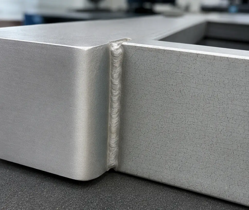
Post-treatment inspection revealed a pronounced optical mismatch: the 6063 profiles showed a bright, transparent silver sheen, whereas the 6061 baseplate appeared dull gray with yellowish undertones. Dark cloudy patches formed across the weld Heat-Affected Zone (HAZ).
The Physical Root Cause
The optical transparency of an anodic oxide layer (Al2O3) depends directly on the purity of the base aluminum:
· 6061 Copper Content (0.15% to 0.40%): Copper intermetallic particles (θ-phase CuAl2) do not dissolve cleanly during sulfuric anodizing; they oxidize into dark, insoluble micro-inclusions that trap light, reducing film clarity.
· 6063 Base Purity (Cu < 0.10%, Fe < 0.35%): Produces a crystalline anodic alumina layer that allows uniform optical transmission.
· When submerged simultaneously in the same electroplating tank, differences in substrate potential cause unequal current density distribution, yielding varying film growth rates and distinct color mismatches.
|
Substrate Alloy Component |
Alloy Copper Content Range |
Anodic Oxide Layer Visual Output |
|
6061-T6 Baseplate |
0.15% to 0.40% Cu |
Grayish hue with reduced transparency |
|
6063-T6 Extruded Upright |
Less than 0.10% Cu |
Bright silver with high specular clarity |
|
ER4043 Weld Seam |
4.5% to 6.0% Si |
Dark charcoal-gray line |
Dazao Engineering Solution
1. DFM Joint Redesign: Whenever optical consistency is required, we advise clients to eliminate welded joints between disparate alloys. We redesign joints into mechanical interlocks using hidden CNC locating dowel pins and high-tensile internal fasteners.
2. Surface Mechanical Pre-Treatment: If welding cannot be avoided, the entire assembly undergoes automated blasting with 120-mesh ceramic beads at 0.35 MPa, followed by a controlled 90-second immersion in sodium hydroxide (50 g/L NaOH at 60∘C) to homogenize the microscopic light refraction index across all zones before anodizing.
Engineering Application Guide: When to Choose 6061 vs 6063 Aluminum
Structural and High-Load Scenarios Requiring 6061-T6 Billet
· High Mechanical Stress and Dynamic Loads: Structural suspension brackets, multi-axis robotic arms, industrial automated slide plates, and aerospace fluid manifolds where high 6061 tensile strength (310 MPa) and 6061 yield strength (276 MPa) are required.
· Massive Material Removal (Hog-Outs): Parts machined from solid plate or block where over 60% of raw material is converted into chips. 6061 produces segmented chips that prevent tool nesting and spindle collisions.
· High-Torque Fastener Assemblies: Threaded ports requiring continuous torque cycling, where shear strength (207 MPa) prevents thread pull-out under dynamic vibration.
Complex Profiles and Cosmetic Enclosures Best Suited for 6063 Extrusions
· Complex Hollow Cross-Sections: Architectural extrusions, sliding tracks, specialized LED lighting fixtures, and modular fluid-cooling plates where near-net shapes can be extruded to minimize machine run time. Learn more about specialized 6063 aluminum CNC machining techniques for complex profiles.
· Cosmetic Consumer Electronics: Tablet frames, luxury audio faceplates, and optical enclosures demanding specular gloss, zero grain boundary streaks, and uniform dye uptake during decorative anodizing.
· High Thermal Dissipation Enclosures: Precision heatsinks where thermal conductivity (201 W/m·K) takes precedence over mechanical yield performance.
Surface Finishing Shootout: 6061 vs 6063 Anodizing, Blasting & Polishing
Surface post-processing performance differs considerably when treating 6061 anodizing surfaces versus 6063 anodizing surfaces. Aligning your post-processing requirements with industrial aluminum surface finishing and anodizing standards ensures optimal cosmetic and protective results.
|
Finishing Process |
6061-T6 Response Profile |
6063-T6 Response Profile |
Engineering Application Note |
|
Type II Clear Anodizing (MIL-A-8625) |
Semi-clear with slight yellow-gray tint; gloss level 60-70 GU. |
Highly transparent, brilliant metallic luster; gloss level >85 GU. |
6063 is standard for consumer-facing external bezels. |
|
Type II Color Anodizing (Black/Blue/Red) |
Consistent dye uptake; deep black is uniform across all lots. |
Crisp color saturation; higher reflectivity with bright base tones. |
Both alloys take organic dyes reliably; 6063 provides higher vibrancy. |
|
Type III Hardcoat (50 µm thickness) |
Microhardness 450 to 500 HV; excellent wear and abrasion resistance. |
Microhardness 380 to 420 HV; lower resistance under high point loads. |
6061 is preferred for sliding wear plates and hydraulic cylinder bores. |
|
Bead Blasting (120-Mesh Glass/Ceramic) |
Uniform matte finish; easily hides fine tool marks (Ra 0.8 µm). |
Rapid matte conversion; requires lower blast pressure to prevent peening. |
Blast pressure for 6063 should not exceed 0.30 MPa to prevent corner rounding. |
|
Chemical Polishing & Bright Dipping |
Moderate gloss; micro-textures remain visible due to alloy elements. |
High specular reflection; mirror-level finishes without clouding. |
6063 is ideal for optical reflectors and decorative trim. |
Manufacturing Cost Economics: Raw Stock, Tooling Amortization & Cycle Time
Selecting between solid billet machining and aluminum extrusion for CNC machining dictates both raw inventory expense and CNC spindle cycle time when evaluating 6061 vs 6063 cost.
1. Raw Stock Material Costs
· Standard 6061 aluminum alloy plate and solid bar are global commodities sold at high market liquidity. Raw material costs typically track spot aluminum indices plus a conversion premium of $0.80 to $1.20 per kg.
· Custom 6063 aluminum profile stock requires an upfront extrusion die investment ($1,200 to $3,500 depending on circle size and mandrel complexity). However, on production runs exceeding 500 units, purchasing net-shape extrusions lowers incoming material weight by 40% to 75% compared to solid rectangular billets.
2. Machining Cycle Time & Spindle Economics
· 6061 Milling Efficiency: Higher shear hardness allows cutting tools to operate at higher feed rates per tooth (fz=0.15 to 0.25 mm/tooth) during roughing, decreasing machine-hour expenses.
· 6063 Extrusion Machining: While cutting speeds must be modulated to manage built-up edge formation, total metal removal volume is drastically lower because internal channels and mounting profiles are pre-formed during extrusion. Spindle run times are often reduced from 45 minutes (from solid plate) to under 8 minutes (secondary profile finishing).
|
Batch Volume Scenario |
Preferred Material Route |
Tooling / NRE Cost |
Unit Cycle Time |
Total Cost Advantage |
|
Prototypes (1 to 20 pcs) |
6061-T6 Solid Billet / Plate |
$0 (No extrusion die) |
High (Full 3D pocketing) |
Lower total project cost; fast delivery (3-5 days). |
|
Pilot Production (20 to 200 pcs) |
6061-T6 Standard Stock |
$0 NRE |
Moderate |
Balanced cost without amortizing specialized tooling. |
|
Mass Production (500+ pcs) |
6063-T6 Custom Extrusion + CNC |
$1,500 Extrusion Tool |
Low (Feature finishing only) |
35% to 55% reduction in unit part cost over billet machining. |
DFM Engineering Checklist & Quality Control Standards at Dazao
Before releasing drawing packages to production, design and procurement teams should verify these five manufacturing baseline checks using our factory-level aluminum CNC machining master handbook:
1. Mechanical Load Verification: Does the component experience dynamic or cantilevered structural loads? If yield requirements exceed 214 MPa, specify 6061-T6 exclusively.
2. Geometric Cross-Section Feasibility: Can uniform wall sections be extruded through a die? If yes, transition from solid block to 6063-T6 profile stock to lower material waste.
3. Post-Machining Anodizing Class: If Class-A cosmetic matching is mandatory across multi-component visual surfaces, designate 6063 with mechanical bead blasting and specify identical batch tank processing.
4. Tolerance Definitions: Do not apply solid-billet tolerances (±0.01 mm) to unmachined extruded walls. Standardize non-machined profile features to EN 755-9 or ISO 2768-m, while applying precision tolerances (±0.01 mm) only to secondary CNC-machined features.
5. Dazao Quality Control Infrastructure: Every production lot at Dazao is verified using Oxford Optical Emission Spectrometry (OES) for alloy chemistry, automated Coordinate Measuring Machines (CMM) for geometric GD&T, Mitutoyo surface profilometers for Ra roughness, and eddy-current coating thickness gauges for anodic layer verification.

FAQs
01.Why does 6063 aluminum stick to CNC cutting tools more than 6061?
02.How do you prevent thin-walled 6063 extrusion profiles from warping during CNC milling?
03.Why do 6061 and 6063 parts show color mismatches when anodized together?
04.Can you tap micro-threads like M2 or M3 reliably in 6063 aluminum?
05.Is it better to hog out 6061 billet or order custom 6063 extrusion for low volumes?
06.Which alloy provides better thread strip resistance under high bolt torque?





