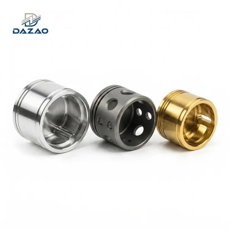

Specifying a brushed aluminum finish requires defining the abrasive grit, mechanical grain lay relative to a physical datum, traverse measurement vector for surface roughness, and pre-anodizing chemical limits to prevent reflection mismatches and costly part rejections.
Applying a mechanical grain texture to raw brushed aluminum substrates enhances visual depth and conceals minor handling marks. However, treating a brushed metal finish as an aesthetic afterthought on an engineering print introduces severe production risks. For precision hardware, a brushed finish for CNC machined parts requires rigorous geometric and surface profile definitions. To streamline shop-floor execution, engineers should review our foundational aluminum CNC machining guide before releasing drawings to production. Without defining the brushed finish grain direction, abrasive medium, pre-treatment chemistry, and post-brushing inspection standards, production batches frequently fail visual quality control at assembly.
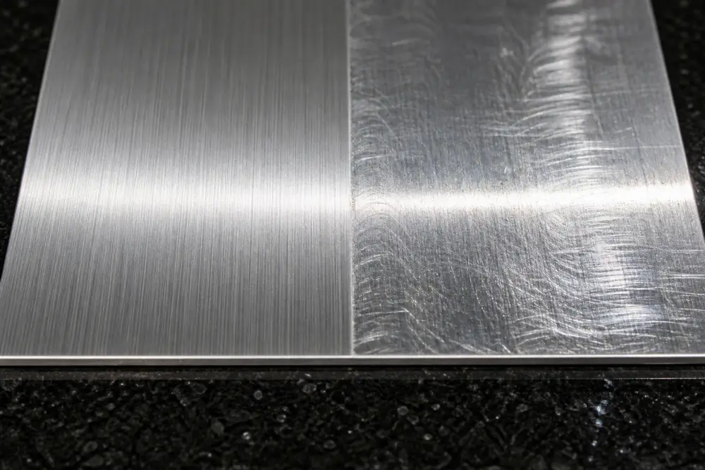
Unspecified Brushed Metal Finish Risks: Costly Scraps and Drawing Ambiguities
The Financial and Assembly Costs of Ambiguous Surface Callouts
Marking a drawing with only the words Brushed Finish or Line Finish forces the manufacturing team to guess the engineering design intent. Machine shops utilize multiple mechanical methods to produce a brushed surface, including wide-belt sanders, stroke sanders, manual non-woven pads, cylindrical wire flap wheels, and oscillating orbital heads.
Each processing method yields a fundamentally different scratch depth, groove spacing, and light reflection pattern. When an engineering drawing lacks exact parameters, prototype parts produced manually in low volumes often look completely different from automated, conveyor-belt-brushed production runs. Ambiguous callouts typically trigger four compounding shop-floor failures:
· Ambiguous abrasive selection, leaving operators to choose arbitrarily between coarse 80-grit or fine 240-grit media.
· Undefined grain vectors, leading to arbitrary parallel, perpendicular, or radial surface textures.
· Uncontrolled metrology vectors, creating disputes over parallel versus perpendicular Ra roughness measurements.
· Uncontrolled anodizing pre-treatment baths, which degrade mechanical micro-peaks into chalky, non-reflective surfaces.
Dazao Production Case Study: 500 Scrapped Telecom Faceplates from Optical Sheen Mismatch
In 2021, Dazao was contracted to machine and finish 500 units of rack-mounted telecommunications server front panels made from Al6061-T6. The customer drawing stated only: Brush to aesthetic finish and clear anodize.
Our machining cells maintained strict aluminum CNC machining tolerances within ±0.025 mm across all primary locating features and held overall face flatness within 0.05 mm. During surface prep, two finishing operators split the batch across two distinct deburring stations: one used a manual pneumatic stroke sander traversing along the 482.6 mm length, while the other utilized a rotary non-woven nylon drum working across the 44.45 mm height.
Both operators produced an average surface roughness (Ra) of roughly 0.8 µm. However, once the parts went through standard pre-anodize caustic etching and type II clear sulfuric anodizing, the physical consequence was immediate:
· Panels brushed along the X-axis exhibited a high-sheen specular reflection under horizontal overhead facility lighting.
· Panels brushed along the Y-axis absorbed light differently, scattering it vertically and appearing two shades darker.
· When assembled into adjacent server bays, the units displayed an unacceptable two-tone optical mismatch.
The entire 500-piece batch was rejected by the customer incoming quality team solely on visual consistency grounds. Dazao absorbed the cost of raw material, machining time, and remanufacturing. This failure prompted our engineering department to formalize an absolute drawing specification protocol that eliminates interpretation errors prior to tool engagement.
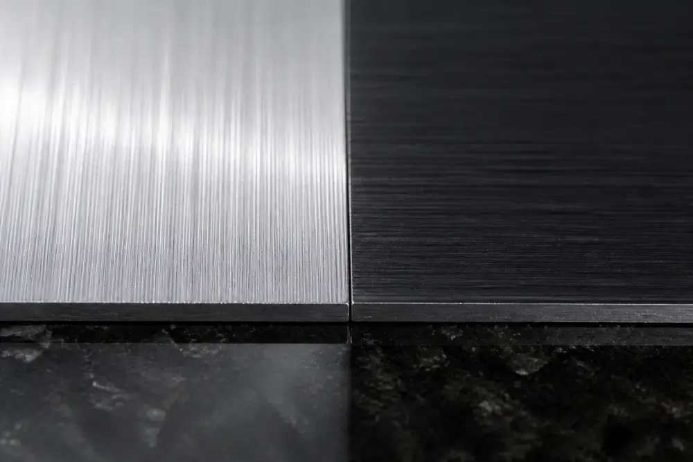
Metal Finishing Comparison: Brushed Finish vs Bead Blasted Finish vs Polished Metal
Selecting the proper finish for mechanical enclosures involves balancing manufacturing cost, structural tolerances, visual uniformity, and functional surface properties. When evaluating total component aesthetics, reviewing our overarching aluminum surface finishing guide helps match functional demands with cosmetic grades.
Brushed Finish vs Bead Blasted Finish: Surface Topography, Cutter Mark Masking & Wear
The debate between a brushed finish vs bead blasted finish centers on directional versus isotropic surface topology:
· Micro-Topography: A brushed finish creates parallel micro-grooves that scatter light unidirectionally. In contrast, bead blasting uses spherical media (typically glass bead #8 to #13, 53 to 105 µm diameter) or angular aluminum oxide to produce non-directional micro-craters. While linear grain highlights part contours, utilizing sandblasting metal parts for surface prep yields an isotropic surface that blends deep cutter scallops.
· Toolmark Masking: Bead blasting excels at hiding continuous cutter path steps from face mills and corner ball endmills up to an Ra 1.6 µm baseline. Brushing cannot eliminate deep endmill step-overs; any cutter gouge deeper than the brush scratch depth remains visible beneath the linear grain. CNC components intended for brushing must be pre-milled to an initial surface finish of Ra 0.8 µm or better. Prior to committing to aesthetic finishes, calculating the overall aluminum CNC machining cost helps teams weigh manual surface prep against automated operations.
· Contamination and Wear: Bead blasted surfaces present a high contact area of open micro-voids, making them susceptible to fingerprint oils, sweat staining, and localized burnishing marks from packaging friction. Brushed surfaces, when sealed via anodization, direct liquids along linear paths, making them easier to clean and significantly more forgiving of light directional abrasions in field service. For components operating in extreme chemical or outdoor environments, switching from linear grain to powder coating aluminum parts provides superior barrier protection.
Brushed Finish vs Polished Metal: Specular Reflectance, Edge Integrity & Dimensional Tolerances
Evaluating a brushed finish vs polished metal requires understanding optical clarity versus dimensional stability:
· Mirror Polishing: Mechanical polishing utilizes progressively finer abrasive compounds (down to 1 µm diamond suspension) to eliminate all macroscopic surface texture, achieving an Ra under 0.05 µm. While this delivers a mirror-like specular reflection, it amplifies underlying material inclusions, weld heat-affected zones, and micro-porosity in billet stock.
· Tolerance Retention: High-luster mechanical buffing rounds sharp exterior part boundaries, distorts counterbores, and erodes critical edge breaks. Brushing with rigid wide-belt equipment preserves face-to-edge squareness and boundary flatness far better than flexible cotton buffing wheels.
· Sliding Friction Interfaces: If the component functions inside an assembly as a mechanical sliding contact, a polished interface minimizes dry sliding friction. A brushed finish should only be used on contact surfaces if the grain direction aligns parallel to the stroke vector. Transverse brushing across a sliding axis acts as a micro-file, accelerating secondary seal or bushing wear.
|
Engineering Parameter |
Brushed Finish |
Bead Blasted Finish |
Polished Finish |
|
Surface Topography |
Anisotropic, parallel linear grooves |
Isotropic, non-directional micro-craters |
Micro-planar, scratch-free specular surface |
|
Typical Target Roughness (Ra) |
0.4 µm to 1.5 µm (measured perpendicular) |
0.8 µm to 3.2 µm (non-directional) |
0.02 µm to 0.1 µm (non-directional) |
|
Pre-Finishing CNC Surface Requirement |
Ra ≤ 0.8 µm (Step-overs fully eliminated) |
Ra ≤ 1.6 µm (Hides standard cutter scallops) |
Ra ≤ 0.4 µm (Requires pre-lapping) |
|
Dimensional Edge Retention |
High (controlled via flat conveyor platens) |
Moderate (micro-erosion at sharp corners) |
Poor (significant boundary edge-rounding) |
|
Handling Mark Sensitivity |
Low (linear texture masks minor scuffs) |
High (burnishes easily; picks up oils) |
Extreme (shows micro-scratches and smudges) |
|
Relative Production Cost Factor |
1.0x (Baseline mechanical finishing) |
0.8x to 1.1x (Process time dependent) |
2.5x to 4.0x (Labor-intensive manual buffing) |
Controlling Brushed Finish Grain Direction and Anisotropic Surface Roughness Ra
To achieve consistency in batch production, surface roughness callouts must account for the directional nature of linear mechanical finishes.
Brushed Finish Grain Direction: ASME Y14.36M Lay Designations and Assembly Datum Alignment
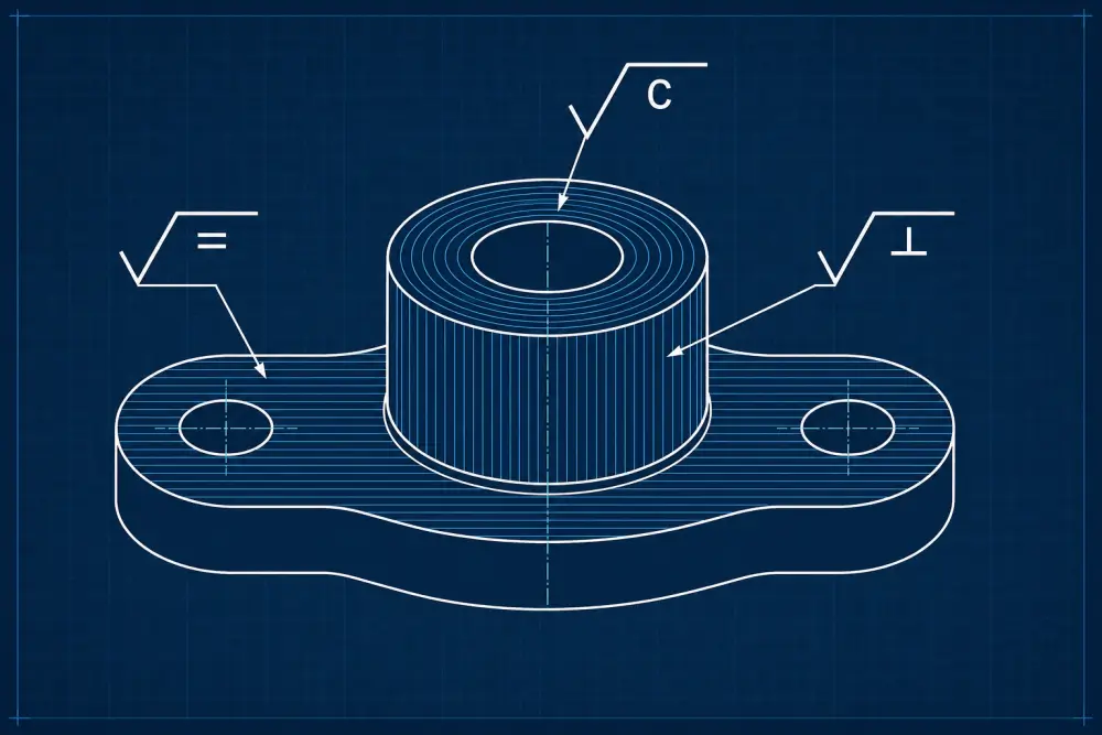
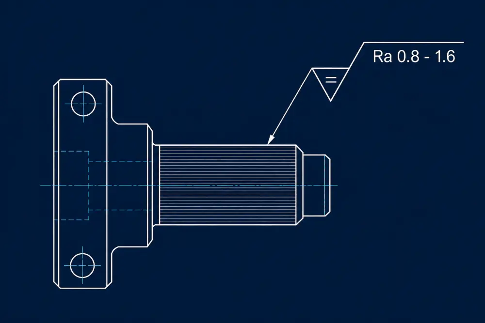
According to ASME Y14.36M and ISO 1302, surface texture symbols applied to brushed parts must include a clear definition of the surface lay. For mechanical parts, using text alone allows too much room for operator error. The engineering drawing must incorporate standardized lay designation symbols positioned directly inside the surface finish check-mark:
· Parallel: The brush lines must run parallel to the boundary line, datum, or view projection plane indicated by the symbol leader line.
· Perpendicular: The brush lines run normal to the indicated projection line or feature boundary.
· Crossed: The lines cross obliquely, typical of dual-head automated wide-belt deburring systems running opposing cross-feed belts.
· Circular or Radial: Generated using rotary lathe fixtures, automated planetary scotch-brite heads, or rotary wire tools around a defined component center point.
Brushed Finish Surface Roughness Metrology: The Transverse vs Longitudinal Measurement Paradox
A primary source of quality disputes between machinists, anodizing subcontractors, and inspection engineers is the directional variance of profilometer measurements on brushed surfaces. To calibrate quality control profilometers across anisotropic grain profiles, engineers can reference our standardized CNC surface roughness chart.
A stylus profilometer dragged across a brushed face records radically divergent values depending on the scan vector:
· Transverse Scan (Perpendicular to Grain): The diamond stylus drops down into every microscopic abrasive furrow and climbs every micro-ridge. A 180-grit belt finish will typically measure an Ra of 1.2 µm to 1.8 µm.
· Longitudinal Scan (Parallel to Grain): The diamond stylus rides inside an individual groove or along a single ridgeline. The same identical component will measure an Ra of 0.2 µm to 0.4 µm.
If an engineering drawing states Ra 0.8 µm maximum without identifying the measurement vector relative to the lay, an inspector measuring perpendicular to the grain will reject parts that pass easily when measured parallel to the grain. Determining brushed finish surface roughness requires establishing explicit scanning vectors. Dazao inspects all brushed components across the grain (transverse) by default, using a 0.8 mm cutoff length with a standard 5 µm diamond stylus tip radius, unless the customer drawing explicitly specifies a parallel evaluation vector.
Abrasive Grit Selection: Mapping Belt Grit Sizes to Measured Ra and Specular Sheen
The physical appearance of a brushed metal finish is determined by the abrasive grain size, backing rigidity, and tool rotational velocity. Fine abrasives generate narrow, closely spaced micro-grooves that scatter high-frequency visible light, creating a satin or semi-gloss appearance. Coarse abrasives cut broad, deep trenches that reflect strong specular highlights along the scratch axis.
|
Grit Rating / Abrasive Media |
Media Material |
Transverse Roughness (Ra) |
Longitudinal Roughness (Ra) |
Visual Characteristic Post-Anodize |
|
80 to 120 Grit Belt |
Aluminum Oxide / SiC |
2.0 µm to 3.5 µm |
0.6 µm to 1.0 µm |
Highly industrial, distinct visible tracks, high glare |
|
180 to 240 Grit Belt |
Aluminum Oxide |
0.8 µm to 1.4 µm |
0.2 µm to 0.4 µm |
Classic industrial architectural look; balanced sheen |
|
320 to 400 Grit Belt |
Silicon Carbide |
0.4 µm to 0.8 µm |
0.1 µm to 0.25 µm |
Fine satin texture, uniform soft reflection |
|
Scotch-Brite (Coarse - Brown) |
Non-woven nylon web |
1.0 µm to 1.6 µm |
0.3 µm to 0.5 µm |
Blended stroke lines, rounded scratch profile |
|
Scotch-Brite (Very Fine - Maroon) |
Non-woven nylon web |
0.3 µm to 0.6 µm |
0.1 µm to 0.2 µm |
Soft diffuse satin, uniform low-glare surface |
Brushed Stainless Steel Finish vs Brushed Aluminum: No. 4 Brushed Finish Mechanics
Understanding the physical behavior of brushed aluminum requires contrasting it with a brushed stainless steel finish. In sheet metal and industrial machinery, stainless steel is routinely specified with a standard No. 4 brushed finish (governed by ASTM A480). This finish is generated using 120-to-150-grit abrasives producing short, discontinuous linear scratches.
The mechanical physics between the two alloys differ significantly:
· Work Hardening vs. Material Smearing: Austenitic stainless steels (such as AISI 304 or 316) work-harden immediately upon tool contact. The abrasive grains cleanly fracture the work-hardened micro-ridges, generating sharp, distinct, crisp edges along every cut furrow. Aluminum alloys (such as 6061 or 5052) are substantially softer, have lower melting temperatures, and exhibit high ductility. Under dry brushing conditions, aluminum micro-chips melt and smear across the surface, loading up the abrasive belt and forming irregular galling tears rather than clean linear troughs.
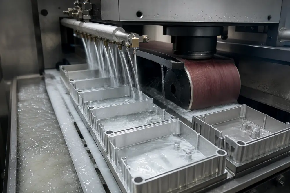
· Lubrication Requirements: Achieving a clean No. 4 finish equivalent on aluminum requires specialized wet-brushing systems utilizing light synthetic emulsions or spray mists. This prevents micro-welding of aluminum particles onto the abrasive belts, which would otherwise leave deep, uncontrolled gouges across the workpiece.
Critical Failure Modes in Brushed Finish for CNC Machined Parts: Factory Blind Spots
Producing a uniform brushed aluminum finish requires controlling thermodynamic and chemical variables that standard machining handbooks omit. While machining handbooks focus strictly on belt speeds and abrasive grit sizes, real-world yield losses stem from micro-chemical erosion, geometric edge deformation, and harmonic vibration during the brushing operation.
Caustic Etch Degradation: How Alkaline Tanks Dissolve Micro-Peaks and Cloud Surface Luster
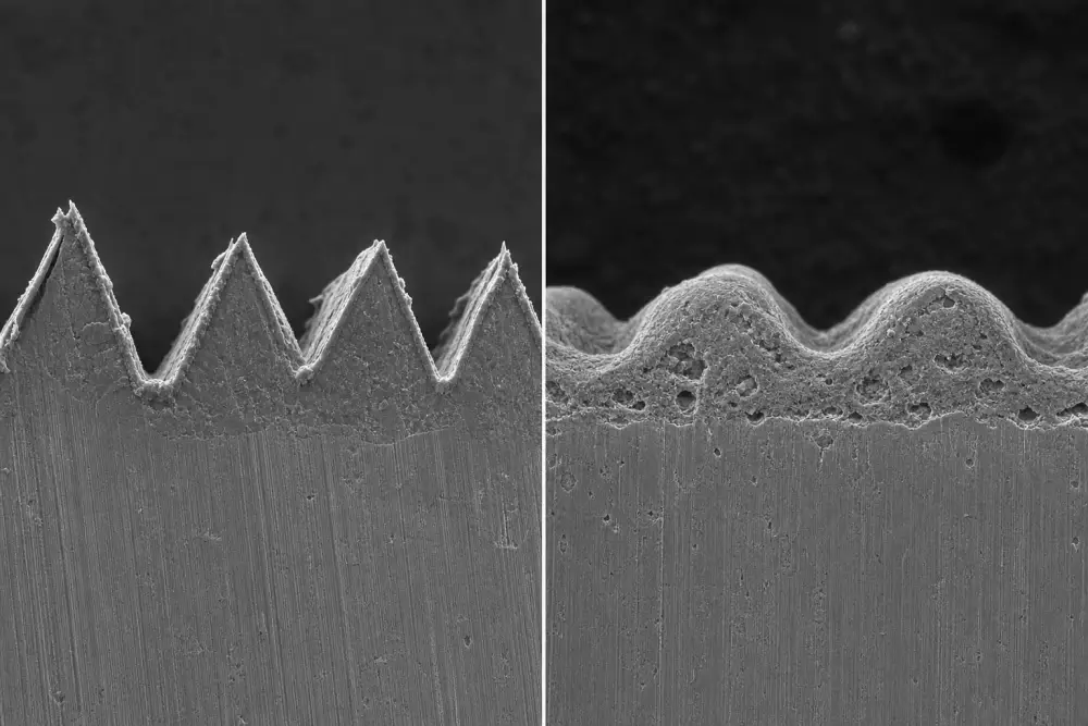
The visual appeal of brushed aluminum relies on sharp micro-peaks and valleys that cleanly refract light. Standard anodizing pre-treatment lines clean and desmut aluminum by running parts through a hot sodium hydroxide caustic bath at 50°C to 65°C for two to five minutes.
While this heavy alkaline etch removes surface contaminants and blends minor handling scratches on standard parts, it degrades a brushed metal finish:
· Sodium hydroxide aggressively attacks the high-energy, sharp crests of mechanical brush grooves.
· The chemical reaction rounds off the microscopic ridges, eroding the peak-to-valley height and turning crisp, directional reflective grooves into broad, rounded troughs.
· The light no longer reflects sharply off directional facets; it scatters into a dull, chalky, hazy surface. The component loses its metallic sheen and appears milky.
Preserving the razor-sharp micro-ridges is necessary before sealing the component under a protective clear anodized aluminum layer. Similar micro-peak preservation rules apply when producing deep metallic luster on black anodized aluminum CNC parts.
The Dazao Production Fix: For all brushed components requiring clear or color anodizing, Dazao bypasses aggressive alkaline etching. We utilize an acid deoxidizer or restrict alkaline immersion to a flash etch cycle under twenty seconds, holding material removal below 0.001 mm. This preserves the sharp micro-crests necessary to retain maximum specular reflectivity under clear or dyed anodic films.
Pocket Boundary Rollover and Chamfer Bleed: Sequence Planning Around Milled Features
Machined enclosures frequently feature milled pockets, O-ring grooves, counterbored fastener holes, and 45-degree edge chamfers. When wide-belt sanding heads or cylindrical rotary brushes pass over these interrupted geometries, two defects appear:
· Edge Burr Rollover: Abrasive belts flex when encountering an open cavity. As the abrasive grains exit the solid face and drop into a pocket, they push ductile aluminum ahead of them, rolling a microscopic, work-hardened burr inward along the pocket rim. Secondary deburring operators who manually scrape these burrs away invariably leave irregular, fish-hook scratch marks that stand out under anodizing.
· Chamfer Grain Bleed: A 45-degree structural chamfer should present a clean, uniform contrast against a brushed primary face. Flexible abrasive media sweeps past the boundary edge, depositing erratic, oblique scratch lines across the machined chamfer facet. This destroys the crisp edge definition of CNC milled housings.
The Dazao Production Fix: Dazao resolves boundary edge-bleed by utilizing high-precision 5-axis CNC machining services to cut final chamfers and precision pockets after surface brushing. Primary face brushing is executed on automated through-feed sanders prior to secondary edge chamfering and precision bore finishing. Machining the chamfers and cutouts after face brushing leaves crisp boundaries with zero rolled burrs and pristine, scratch-free beveled borders.
Thin-Wall Vibration and Tiger Striping: Preventing Acoustic Chatter Under Vacuum Hold-Down
Machined electronic chassis covers and RF shields often feature wall thicknesses between 1.0 mm and 2.0 mm. Fixturing these thin-section parts on flatbed vacuum chucks for automated belt brushing introduces an unexpected acoustic-mechanical defect known as tiger striping.
As the abrasive belt contacts the thin plate at surface speeds exceeding 15 meters per second, the cutting friction induces high-frequency micro-deflections in the unsupported center zones of the plate. Despite hundreds of millibars of vacuum hold-down pressure, the workpiece slips dynamically in micro-increments against the vacuum gasket.
This intermittent stick-slip cycle causes the abrasive grains to bite at rhythmic intervals, leaving visible transverse stripes spaced 2 mm to 5 mm apart across the face. These chatter waves remain invisible under diffuse shop lighting, but reveal themselves immediately under directional 5000K display lights.
The Dazao Production Fix: For aluminum components with wall thicknesses under 2.5 mm, Dazao abandons compliant perimeter vacuum gaskets. We build dedicated, rigid aluminum nesting fixtures matched to the underside topology of the part, securing the component via low-profile peripheral mechanical clamps and semi-rigid water-soluble adhesives. Brushing parameters are adjusted to lower surface feed rates using fine 320-grit silicon carbide belts backed by synthetic flood coolant, damping mechanical chatter completely.
Substrate Metallurgy in Brushed Aluminum: Alloy Selection and Extrusion Grain Conflicts
The chemical makeup and temper of the base aluminum alloy directly dictate how cleanly abrasive particles slice the metal rather than tearing it.
|
Alloy & Temper |
Hardness (HB) |
Brushing Behavior |
Anodizing Compatibility |
Recommended Abrasive & Lubricant |
|
Al6061-T6 |
95 HB |
Excellent; crisp chip shear, distinct grooves |
High; consistent tone across clear/color tanks |
180 to 240 Grit Al2O3, dry or synthetic mist |
|
Al5052-H32 |
60 HB |
Ductile; prone to galling, smearing, and belt loading |
Moderate; slight yellowish shift under clear anodize |
240 to 320 Grit SiC, continuous flood coolant required |
|
Al7075-T6 |
150 HB |
Brittle-hard; produces micro-fractures, cloudy haze |
Poor for Class A; prone to blotchy white patches |
320 to 400 Grit SiC, wet emulsion processing |
|
Al6063-T5 (Extruded) |
75 HB |
Good along extrusion axis; tearing across extrusion |
High; uniform satin appearance when aligned |
180 to 240 Grit Scotch-Brite, light synthetic lubricant |
Al6061-T6: The Optimal Alloy for Crisp Shear and Clean Directional Grooves
Due to balanced magnesium and silicon alloying elements that precipitate into magnesium silicide hardening phases, Al6061-T6 shears cleanly when struck by aluminum oxide grains. The material does not smear excessively, and scratch edges remain sharp. It represents the most reliable baseline for custom mechanical panels.
Al5052-H32: Managing Ductile Smearing, Abrasive Loading, and Galling Marks
Commonly selected for bent chassis brackets, Al5052 has higher ductility and lower shear strength than 6061. Under standard dry belt sanding, the alloy tears rather than shears, leaving irregular burrs along scratch margins. Dry processing quickly loads the abrasive paper with melted aluminum gum, producing irregular scoring marks. Al5052 requires wet processing using emulsion coolants to wash chips out of the belt matrix.
Al7075-T6: Zinc Phase Segregation and Post-Anodize Milky Clouding Defects
With 5.1% to 6.1% zinc content, Al7075-T6 is exceptionally hard and brittle. Abrasive grits generate micro-cleavage fractures across the crystal boundaries rather than smooth grooves.
When subjected to acid desmutting and anodizing baths, these micro-cleavage sites trap chemical salts and etch at accelerated rates compared to the surrounding matrix. The visual result is a mottled, cloudy white appearance beneath the linear grain. Dazao actively advises engineering clients to avoid 7075 when designing Class A cosmetic faceplates.
Extruded Grain Alignment: Eliminating Optical Interference Fringes on 6063 Profiles
Extruded profiles (such as 6063 or 6061 shapes) possess an inherent longitudinal microstructural grain produced by the extrusion die. If an engineer specifies a grain direction skewed at an angle (for example, 15 degrees or 45 degrees) relative to the extrusion profile length, two competing grain patterns interact.
Incident light reflects simultaneously off the underlying extrusion bands and the mechanical brush furrows, generating visual moire patterns and optical interference fringes. To prevent this effect, mechanical brush lay on extruded stock must always align parallel to the extrusion axis.
How to Specify Brushed Finish on Engineering Drawing: Practical DFM Callout Templates
To transform an aesthetic preference into an unambiguous, verifiable manufacturing requirement, mechanical prints must integrate four distinct control layers. Mastering how to specify brushed finish on engineering drawing requires structuring boundary lines, standard symbols, roughness envelopes, and chemical notes into a cohesive callout block.
The Four-Pillar Drawing Specification Framework: Boundary, Lay, Ra, and Chemistry
1. Surface Boundary Definition: Mark visible exterior faces as Class A surfaces using dashed phantom boundary lines or surface flag notes. Never leave the entire 3D model under a blanket general drawing note.
2. ASME Y14.36M / ISO 1302 Lay Symbol: Place a surface texture check-mark pointing directly to the face. Include the appropriate lay symbol (Parallel or Perpendicular) referenced to a primary mechanical datum.
3. Roughness Limits and Measurement Vector: State both upper and lower roughness limits (Ra and Rz) along with the mandatory measurement direction relative to the grain vector.
4. Post-Processing Chemistry Sequence: Define the exact chemical routing order to prevent anodizers from altering the mechanical surface profile through excessive etching.
Production-Ready Drawing Note Blocks for Class A Brushed Aluminum Panels
Incorporate the following standardized drawing notes into your CAD blocks:
Example 1: Class A Flat Front Panel Callout
· Surface indicated by phantom outline to receive directional mechanical brushed finish.
· Grain direction must run parallel to Datum A within a tolerance of ±1.0 degree.
· Surface roughness measured transverse (normal) to grain direction: Ra 0.8 µm to 1.4 µm; Rz maximum 6.0 µm (evaluation length = 4.0 mm, cutoff = 0.8 mm).
· Pre-anodize etching restricted to light acid desmut or flash degrease only. Total metal removal shall not exceed 0.001 mm per face.
· Finish with MIL-A-8625 Type II, Class 1 clear anodize, coating thickness 10 to 15 µm. Seal via nickel acetate.
Example 2: Enclosure Side Flange Callout
· Finish: No. 4 equivalent directional brushed finish produced via 180-grit abrasive.
· Grain lay: Perpendicular to Datum B as designated by surface symbol.
· Surface roughness measured parallel to grain direction: Ra 0.2 µm to 0.4 µm maximum.
Physical Boundary Samples: Establishing Lighting, Distance, and Dwell Inspection Criteria
Surface metrology alone cannot fully capture optical reflectivity and aesthetic perception. Every production batch undergoes validation inside our quality inspection and metrology laboratory, verifying Ra thresholds under calibrated profilometer arrays. High-reliability programs at Dazao require physical reference samples to govern production runs.
Three boundary sample plaques must be manufactured, signed off, and sealed:
· Nominal Standard: The target median for scratch depth, line density, and luster.
· Upper Limit (Coarse / Dark): Maximum allowable grain depth and lowest acceptable gloss unit measurement.
· Lower Limit (Fine / Bright): Minimum allowable scratch definition before the surface appears over-polished or washed out.
Standardized Inspection Protocol: Parts must be evaluated in accordance with modified ASTM D1729 parameters:
· Illumination: Overhead balanced daylight luminaire producing 1000 lux (±150 lux) at a color temperature of 5000K (CIE D50 or D65).
· Viewing Distance: 450 mm to 600 mm from the inspector eye to the component surface.
· Inspection Angle: Part rotated through a 45-degree angle of incidence relative to the light path.
· Evaluation Dwell Time: Five seconds maximum per face. Any surface defect not visible within five seconds under these parameters is deemed acceptable, preventing protracted delivery delays over sub-micron visual noise.
Supplier Capability Checklist: Automated Wide-Belt Sanding vs Manual Hand Scuffing
Evaluating contract manufacturers for brushed component production requires probing beyond standard machine lists. Use the following capability checklist when auditing prospective machine shops:
|
Evaluation Category |
Red Flag (High Failure Risk) |
Dazao Certified Standard |
|
Brushing Equipment |
Manual off-hand bench grinders, hand-held pneumatic orbital sanders |
Automated PLC-controlled through-feed wide-belt sanders with variable feed rates |
|
Fixturing Strategy |
Operators holding parts by hand against moving belts |
Dedicated flat vacuum platens and custom rigid aluminum support nests |
|
Coolant Integration |
Dry sanding only; aluminum dust buildup on belt media |
Wet grinding capability utilizing chilled synthetic rust-inhibited emulsions |
|
Surface Metrology |
Handheld tactile comparator plates only |
Contact stylus profilometers with configurable cutoff filters and diamond tips |
|
Chemical Integration |
Outsourced anodizing with no chemical etching controls |
Dedicated anodize partners auditing pre-etch bath concentrations and material loss |
|
Material Handling |
Bare hand contact; parts nested metal-on-metal in tote bins |
Lint-free nitrile gloves mandatory; custom compartmentalized ESD foam trays |
Handling and Packaging Controls
A freshly generated brushed aluminum surface has high surface energy and exposed, unoxidized metallic peaks. If shop floor personnel handle un-anodized parts with bare hands, natural skin salts and amino acids penetrate the micro-grooves within seconds. This leaves permanent latent fingerprint etchings that show up vividly after anodizing and cannot be cleaned off.
At Dazao, operators handle brushed parts exclusively using powder-free nitrile gloves. Immediately following anodizing and hot water sealing, components undergo ultrasonic cleaning and hot air drying before receiving an automated application of low-tack, residue-free polyethylene protective tape (50 µm to 75 µm thickness).
This barrier protects the directional micro-peaks from rubbing against packaging paperboard during international transit, ensuring parts arrive on the customer assembly floor in pristine condition.

FAQs
01.Why did my brushed aluminum part turn cloudy and dull after clear anodizing?
02.Why does my profilometer show conflicting Ra readings on the same brushed surface?
03.How do you prevent burr rollover inside milled pockets during surface brushing?
04.Why do adjacent brushed panels appear as different colors when assembled together?
05.What causes faint zebra or tiger stripes on thin brushed aluminum plates?
06.Can I specify a standard No. 4 finish on an aluminum engineering drawing?