6082 aluminum (EN AW-6082 / AlSi1MgMn) provides 15% to 20% higher yield strength and superior fatigue resistance compared to standard 6061-T6. For precision CNC components requiring extensive pocketing or asymmetric material removal, specifying 6082-T651 rolled plate over standard 6082-T6 extrusion prevents internal residual stress release, which otherwise induces workpiece warping up to 0.50 mm over a 300 mm span. Tooling for precision 6082 aluminum machining requires high positive rake angles (+12 to +18 degrees), polished flutes, and high-pressure coolant (minimum 20 bar) to manage the abrasive manganese silicide dispersoids and prevent built-up edge (BUE).
EN AW-6082 CNC Machining: Chemical Composition and Mechanical Properties
Why 6082 Structural Aluminum Outperforms 6061 in Load Frames?
6082 aluminum belongs to the 6000-series aluminum-magnesium-silicon group, standardized in Europe under EN AW-6082 (DIN 3.2315 / ISO AlSi1MgMn). While North American precision manufacturing historically defaulted to ASTM 6061-T6, global structural engineering across rail transport, automotive subframes, marine structures, and high-load robotics end-effectors increasingly mandates 6082. For engineers seeking a broader foundation across lightweight alloys, reviewing precision aluminum CNC machining fundamentals provides an essential baseline before diving into specific high-load grades.
The primary driver is load-bearing capacity. 6082 structural aluminum retains high corrosion resistance and weldability while offering significantly higher mechanical thresholds under static and dynamic loading.

Design engineers frequently commit an empirical error by treating 6082 as an exact drop-in replacement for 6061 with identical machining parameters. While both share the Al-Mg-Si baseline, the higher silicon and manganese content in 6082 alters:
· The chip formation mechanism during high-speed milling.
· Flank wear rates on uncoated carbide cutting tools.
· The propensity for residual stress release during multi-axis machining.
Material Classification: Medium-to-High Strength Structural Aluminum Alloy
Designations: EN AW-6082, AlSi1MgMn, DIN 3.2315, ISO 6082, UNS A96082
Primary Alloying Elements: Silicon (0.70 to 1.30%), Manganese (0.40 to 1.00%), Magnesium (0.60 to 1.20%)
Chemical Breakdown: The Impact of Manganese on 6082 Aluminum Machinability
The mechanical performance of 6082 stems directly from its controlled addition of manganese (Mn) alongside magnesium (Mg) and silicon (Si).
|
Element |
Weight Percentage (wt%) in EN AW-6082 |
Weight Percentage (wt%) in ASTM 6061 |
Metallurgical Function |
|
Silicon (Si) |
0.70 to 1.30 |
0.40 to 0.80 |
Combines with Mg to form Mg2Si hardening precipitates |
|
Manganese (Mn) |
0.40 to 1.00 |
Max 0.15 |
Forms Al12(Fe,Mn)3Si dispersoids; controls grain growth |
|
Magnesium (Mg) |
0.60 to 1.20 |
0.80 to 1.20 |
Co-precipitates with Si for artificial aging hardening |
|
Iron (Fe) |
Max 0.50 |
Max 0.70 |
Impurity; forms brittle intermetallic phases |
|
Chromium (Cr) |
Max 0.25 |
0.04 to 0.35 |
Grain size control and stress corrosion resistance |
|
Zinc (Zn) |
Max 0.20 |
Max 0.25 |
Impurity control; secondary strengthening |
|
Titanium (Ti) |
Max 0.10 |
Max 0.15 |
Grain refiner added during billet casting |
|
Copper (Cu) |
Max 0.10 |
0.15 to 0.40 |
Lower in 6082 to enhance intergranular corrosion resistance |
|
Aluminum (Al) |
Remainder |
Remainder |
Base matrix |
The Manganese Dispersoid Effect
In 6061, manganese is treated as a trace element (under 0.15%). In 6082, manganese is intentionally alloyed between 0.40% and 1.00%. During homogenization and solution heat treatment, manganese forms fine, insoluble Al12(Fe,Mn)3Si and Al6Mn intermetallic dispersoid particles.
These dispersoids provide three fundamental metallurgical effects:
1. Zener Pinning Effect: They pin migrating grain boundaries during hot extrusion and thermal processing, suppressing recrystallization and maintaining a fine fibrous grain structure.
2. Elevated Dislocation Density: During plastic deformation, these particles create Orowan looping obstacles, forcing higher shear stress requirements for dislocation bypass.
3. Abrasive Tool Interaction: While enhancing structural strength, these hard sub-micron dispersoids directly accelerate mechanical micro-abrasion along the tool flank during 6082 aluminum milling and turning.
Engineering Data: Physical and Mechanical Thresholds for Precision CNC Design
To ensure accurate engineering calculations for FEA (Finite Element Analysis) and structural validation, the physical and mechanical properties of 6082 in its primary tempers are quantified below.
|
Property Parameter |
Metric Value (EN AW-6082-T6 / T651) |
Imperial Value (EN AW-6082-T6 / T651) |
Testing Standard |
|
Density |
2.70 g/cm³ |
0.0975 lb/in³ |
ASTM B311 |
|
Elastic Modulus (E) |
70 GPa |
10.15 x 10⁶ psi |
ASTM E111 |
|
Shear Modulus (G) |
26.4 GPa |
3.83 x 10⁶ psi |
ASTM E143 |
|
Poisson Ratio |
0.33 |
0.33 |
ASTM E132 |
|
Ultimate Tensile Strength (Rm) |
310 to 340 MPa |
45.0 to 49.3 ksi |
EN ISO 6892-1 |
|
Tensile Yield Strength (Rp0.2) |
260 to 310 MPa |
37.7 to 45.0 ksi |
EN ISO 6892-1 |
|
Elongation at Break (A50mm) |
8% to 11% |
8% to 11% |
EN ISO 6892-1 |
|
Brinell Hardness (HBW) |
95 to 110 HBW (10/1000) |
95 to 110 HBW |
EN ISO 6506-1 |
|
Thermal Conductivity (20°C) |
170 to 190 W/(m·K) |
98.2 to 109.8 BTU/(hr·ft·°F) |
ASTM E1461 |
|
Coefficient of Thermal Expansion (20-100°C) |
23.1 x 10⁻⁶ /K |
12.8 x 10⁻⁶ /°F |
ASTM E228 |
|
Electrical Conductivity (20°C) |
24 to 28 MS/m (41-48% IACS) |
41 to 48% IACS |
ASTM E1004 |
Key Yield Strength Comparison:
· 6082-T6 Yield Strength (Rp0.2): 260 to 310 MPa
· 6061-T6 Yield Strength (Rp0.2): 240 to 275 MPa
· Net Yield Strength Gain: +8.3% to +22.7% (Design dependent)
6082 T6 vs 6082 T651 Aluminum Machining: Internal Stress and Distortion Control
Quench Stress Mechanics: Why 6082-T6 Warps During Deep Cavity Milling
The choice between 6082 T6 aluminum and 6082 T651 aluminum represents the single most significant factor determining dimensional stability in precision 6082 aluminum machining.
Heat Treatment Nomenclature Breakdown:
· T6 Temper: Solution heat treated, water quenched, and artificially aged to peak precipitation hardness.
· T651 Temper: Solution heat treated, water quenched, stress-relieved by controlled permanent plastic stretching (1.5% to 3.0% elongation), and artificially aged.
The Quench Stress Mechanism
During the rapid water quenching step of the T6 cycle, the outer surface of a thick aluminum plate or profile cools at exceeding rates (e.g., >300°C/second), contracting immediately. The interior core cools at a lower rate, insulated by the surrounding aluminum.
When the core finally cools and contracts, it is mechanically constrained by the already rigid outer shell. This thermal gradient locks a parabolic residual stress profile into the stock:
· Compressive Stress on the Outer Skin: -50 MPa to -120 MPa
· Tensile Stress in the Geometric Center: +50 MPa to +120 MPa
Residual Stress Profile Equation across Plate Thickness (z-axis):
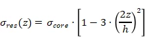
Where:
· h= total plate thickness
· z = distance from neutral mid-plane (−h/2≤z≤h/2)
· σcore = maximum tensile residual stress at the core center
When a CNC mill cuts a deep pocket or removes material asymmetrically from one side of a standard 6082-T6 billet, the balance of internal forces is destroyed:

The remaining material bends and twists until a new internal moment equilibrium is reached. On a 25 mm thick component machined from standard 6082-T6 plate, asymmetric pocketing regularly causes out-of-plane bowing exceeding 0.40 mm to 0.80 mm across a 200 mm length.

The T651 Mechanical Stress-Relief Solution
The 6082 T651 aluminum machining standard addresses this problem at the mill level. Prior to artificial aging, the quenched plate is loaded into a heavy industrial stretcher and pulled plastically along its rolling axis by 1.5% to 3.0% permanent set strain.
This mechanical yielding overrides the elastic thermal stress network:
1. Compressive and tensile zones both reach the yield point (σ≥Rp0.2).
2. When the stretching load is released, the elastic strain recovery is uniform throughout the cross-section.
3. Residual stress drops from up to ±120 MPa to less than ±15 MPa.
Machining Flatness Comparison on 300 mm x 150 mm x 20 mm Plate (50% Volume Asymmetric Cavity):
· 6082-T6 Raw Stock: Final part flatness error = 0.35 mm to 0.65 mm (Requires post-straightening)
· 6082-T651 Raw Stock: Final part flatness error = 0.02 mm to 0.04 mm (Directly maintains drawing tolerance)
6082 Aluminum Plate Machining vs Extruded Profiles
Procurement teams frequently attempt to machine complex prismatic parts from thick extruded bars or profiles rather than rolled plates due to lower raw stock material costs. This creates severe mechanical and dimensional issues.
|
Material Form Metric |
Rolled Plate (EN 485-2) |
Extruded Profile/Bar (EN 755-2) |
Impact on Precision Machining |
|
Internal Stress Level |
Minimal (when specified as T651) |
High to Very High (even in T6) |
Extruded bars experience severe twist and warp upon outer skin removal |
|
Grain Structure |
Equiaxed to planar rolled orientation |
Highly elongated, fibrous parallel to extrusion vector |
Directional mechanical property variance (Anisotropy) |
|
Longitudinal Yield (L) |
270 to 300 MPa |
260 to 310 MPa |
Matched strength parallel to process direction |
|
Transverse Yield (LT/ST) |
260 to 290 MPa (Consistent) |
210 to 240 MPa (Up to 25% drop) |
Significant strength loss across short transverse (ST) axis |
|
Internal Micro-Porosity |
Low (Heavy cross-rolling passes) |
Moderate to High (Extrusion weld lines, central cavitation) |
Risk of vacuum leaks in pneumatic/hydraulic blocks |
|
Anodizing Color Uniformity |
High consistency across surface |
Pronounced structural banding along extrusion lines |
Visual streak defects on visible cosmetic surfaces |
Raw Material Quality Control: Mill Test Certificate (MTC) and IQC Verification
To prevent substandard material integration, Dazao Machinery enforces the following incoming quality control (IQC) protocol for EN AW-6082 CNC machining orders:
Step 1: Mill Test Certificate (MTC) Validation
· Verify compliance with EN 10204 Type 3.1.
· Confirm full chemical breakdown (Check that Mn >= 0.40% and Si >= 0.70%).
· Ensure the temper designation states T651 (stretching confirmation) rather than generic T6.
Step 2: Ultrasonic Flaw Detection (For Plate Thickness >= 40 mm)
· Inspection standard: EN 4050-4 / AMS-STD-2154 Class A.
· Reject stock exhibiting center-line segregation or micro-void clusters exceeding 0.8 mm FBH equivalent.
Step 3: Eddy Current Electrical Conductivity Testing
· Testing standard: ASTM E1004.
· Target range for 6082-T6 / T651: 24.0 to 28.0 MS/m (41.4% to 48.3% IACS).
· Deviations below 23.0 MS/m indicate improper solution quenching; values above 30.0 MS/m indicate over-aging (T7x state) with compromised tensile strength.
Step 4: Micro-Hardness Verification
· Testing standard: ISO 6506-1.
· Minimum acceptance threshold: 95 HBW (converted from 5-point random surface sampling).
6082 Aluminum Milling and Turning: Speeds, Feeds, and Tooling Protocols
High-Efficiency 6082 Aluminum Milling Parameters: Speeds, Feeds, and MRR Matrix
Due to its manganese-induced shear resistance, 6082 aluminum milling requires rigid machine setups, balanced tooling holders (HSK-A63 or BBT40 balanced to G2.5 at 20,000 RPM), and aggressive feed profiles. When executing complex structural parts with deep cavities, utilizing professional 5-axis custom CNC milling services ensures dynamic toolpath stabilization and minimal tool deflection.
Key Milling Formulas:
· Cutting Speed: Vc=(π⋅D⋅n)/1000 [m/min]
· Feed Rate: Vf=fz⋅z⋅n [mm/min]
· Metal Removal Rate (MRR): Q=(ap⋅ae⋅Vf)/1000 [cm³/min]
· Chip Thickness in Trochoidal Milling:  [mm]
[mm]
Milling Parameter Matrix for 6082-T651 (Solid Carbide, Polished Flutes)
|
Tool Diameter (D) |
Operation Type |
Cutting Speed (Vc) |
Spindle Speed (n) |
Tooth Feed (fz) |
Axial Depth (ap) |
Radial Width (ae) |
MRR (Q) |
|
6.0 mm (3-Flute) |
Slotting (Full Width) |
350 m/min |
18,500 RPM |
0.045 mm/z |
6.0 mm (1.0D) |
6.0 mm (1.0D) |
15.0 cm³/min |
|
6.0 mm (3-Flute) |
Trochoidal Roughing |
500 m/min |
26,500 RPM |
0.080 mm/z |
12.0 mm (2.0D) |
0.60 mm (0.10D) |
45.8 cm³/min |
|
10.0 mm (3-Flute) |
Shoulder Profiling |
450 m/min |
14,300 RPM |
0.090 mm/z |
15.0 mm (1.5D) |
3.0 mm (0.30D) |
173.7 cm³/min |
|
12.0 mm (3-Flute) |
Dynamic High-Feed |
600 m/min |
15,900 RPM |
0.120 mm/z |
24.0 mm (2.0D) |
1.20 mm (0.10D) |
164.8 cm³/min |
|
16.0 mm (3-Flute) |
Heavy Roughing |
550 m/min |
10,900 RPM |
0.150 mm/z |
20.0 mm (1.25D) |
8.0 mm (0.50D) |
784.8 cm³/min |
|
20.0 mm (3-Flute) |
High-Efficiency Roughing |
650 m/min |
10,300 RPM |
0.180 mm/z |
30.0 mm (1.5D) |
4.0 mm (0.20D) |
667.4 cm³/min |
|
50.0 mm (5-Insert) |
Face Milling (Rough) |
800 m/min |
5,100 RPM |
0.160 mm/z |
3.5 mm |
37.5 mm (0.75D) |
1,071.0 cm³/min |
|
12.0 mm (3-Flute) |
Surface Finishing |
700 m/min |
18,500 RPM |
0.040 mm/z |
18.0 mm (1.5D) |
0.15 mm (0.012D) |
6.0 cm³/min (Ra 0.4) |

Cutting Tool Geometries and DLC Coating Strategies for 6082 Alloys
Standard general-purpose end mills designed for steels or brass fail rapidly on 6082 due to its dual challenge: high chemical affinity for aluminum at elevated temperatures (causing edge welding) and abrasive micro-dispersoids.
Optimal Tool Geometry Specifications for 6082-T6 / T651:
· Radial Rake Angle: +14 to +18 degrees (Positive, shearing action)
· Axial Rake Angle: +10 to +14 degrees
· Radial Clearance Angle: +10 to +14 degrees (Prevents workpiece flank rubbing)
· Helix Angle: 40 to 45 degrees (Rapid vertical chip evacuation)
· Core Thickness: 55% to 60% of outer diameter (Maximizes flute chip space)
· Cutting Edge Preparation: Sharp edge with micro-honing <= 5 microns (No heavy edge radius or T-land)
Tool Coating Assessment Matrix
|
Tool Substrate and Coating |
Friction Coeff. vs Al |
Micro-Hardness (HV) |
Built-Up Edge (BUE) Resistance |
Tool Life Index in 6082 |
Primary Machining Application |
|
Uncoated Solid Carbide (Polished Flutes) |
0.25 |
~1,600 |
Very High (When Ra<0.1μm) |
1.00 (Baseline) |
Finishing, fine detail, thin-wall features |
|
DLC (Diamond-Like Carbon / ta-C) |
0.05 to 0.10 |
4,000 to 6,000 |
Extreme (Non-stick interface) |
3.50 to 5.00 |
Dry/MQL high-speed machining, high-volume runs |
|
ZrN (Zirconium Nitride) |
0.20 |
~2,800 |
High |
1.80 to 2.20 |
Wet heavy roughing, profile pocketing |
|
TiB2 (Titanium Diboride) |
0.15 |
~3,500 |
Very High |
2.50 to 3.00 |
Heavy roughing in abrasive castings and 6082 plate |
|
AlTiN / AlCrN (Standard Steel Coatings) |
>0.60 |
~3,200 |
Very Low (Severe chemical welding) |
0.20 (Do Not Use) |
PROHIBITED: Aluminum in coating welds to 6082 matrix |
CNC Turning 6082 Aluminum: Chipbreaker Selection and Ribbon Chip Control
When executing 6082 aluminum turning operations on twin-spindle live-tooled mill-turn centers, chip control requires strict parameter thresholds.
Because 6082 has high elongation (8% to 11%), running at sub-optimal feed rates produces long, continuous stringy chips (bird-nesting). These wrap around the rotating spindle, mar surface finishes, and cause tool breakage.
Turning Parameter Protocols for 6082-T651:
· Insert Geometry: VCGT, CCGT, or DCGT ground polished carbide with positive ground chipbreaker (e.g., AK / AL chipbreaker style).
· Nose Radius: 0.4 mm for finish turning (Ra 0.8 achieved easily); 0.8 mm for heavy roughing.
· Cutting Speed (Vc): 300 to 700 m/min.
· Feed Rate (f): Roughing = 0.20 to 0.40 mm/rev; Finishing = 0.06 to 0.12 mm/rev.
· Depth of Cut (ap): Roughing = 1.5 to 4.0 mm; Finishing = 0.20 to 0.50 mm.
Minimum Feed Rate Rule for Chip Breaking:
fmin≥0.12 mm/rev
Operating below 0.10 mm/rev prevents the chipbreaker from generating the bending stress required to fracture the 6082 chip, producing hazardous ribbon chips.
High-Pressure Coolant and Thermal Expansion Control in Precision Machining
Cooling performance directly dictates cycle time and tolerance holding in custom 6082 aluminum parts. Aluminum exhibits a high thermal expansion coefficient (23.1×10⁻⁶/K):
ΔL=L0⋅α⋅ΔT
On a 400 mm long structural rail, a temperature rise of only 15°C during aggressive roughing expands the part by:
ΔL=400×(23.1×10−6)×15=0.1386 mm
This expansion instantly violates standard ISO 2768-m or fine positional tolerances (e.g., ±0.025 mm).
Coolant Management Parameters for 6082 Machining:
1. Emulsion Concentration: 8.0% to 10.5% (Refractometer reading). Concentrations below 6% cause micro-welding; concentrations above 12% cause foaming and surface staining.
2. Emulsion Base: Semi-synthetic or synthetic ester-based fluid with active non-ferrous anti-corrosion inhibitors (pH maintained strictly between 8.8 and 9.2).
3. Pressure Delivery:
· Standard Flooding: 3 to 6 bar (Adequate for external face profiling only).
· Through-Spindle / High-Pressure Coolant (HPC): 20 to 70 bar directed at tool-workpiece interface.
4. Primary Function of HPC (20 to 70 bar):
· Overcomes the rotational air barrier generated by tools spinning >12,000 RPM.
· Mechanically hydraulic-blasts chips out of deep slots and pockets.
· Quenches the shear zone instantly, keeping bulk part temperature rise under 3°C throughout the entire cycle.
Precision 6082 Aluminum Machining: Shop-Floor Failure Analysis and Solutions

Overcoming Micro-Feature Grain Boundary Tearing and Manganese Segregation
During the execution of precision 6082 aluminum machining on features with dimensions below 1.0 mm (such as M1.2 to M2.5 micro-threads, thin heat-sink fins under 0.40 mm, or sharp knife-edge seals), machining failure rates rise sharply if standard 6061 speeds and feeds are applied.
Physical Failure Mechanism
Because 6082 contains up to 1.00% manganese, coarse intermetallic precipitates of Al12(Fe,Mn)3Si and Al6Mn align along the principal rolling or extrusion direction. When a micro-end mill (diameter under 1.0 mm) or micro-tap engages these microstructural bands:
· The local micro-hardness spikes from 95 HBW to over 140 HBW at the particle boundary.
· The cutting edge experiences cyclic impact shock loading rather than continuous plastic shearing.
· The high yield strength of 6082 (260 to 310 MPa) causes microscopic grain boundary tearing along the shear plane, creating irregular edge breakout, micro-burrs, and dimensional instability on fine features.
Micro-Feature Machining Rules at Dazao:
1. Tool Selection: Ultra-fine grain solid carbide (grain size <= 0.2 microns) with Diamond-Like Carbon (DLC) coating.
2. Edge Honing: Cutting edge radius controlled strictly between 1.0 and 2.0 microns.
3. Feed Compensation: Reduce feed per tooth (fz) to 0.005 to 0.012 mm/tooth during final profile passes.
4. Lubrication: Minimum Quantity Lubrication (MQL) with high-ester vegetable oil delivered at 6 bar aerosol pressure.
Eliminating Tiger Stripe Defects and Extrusion Streaks in Anodized 6082 Parts
A common defect in custom 6082 aluminum parts is the emergence of longitudinal visual stripes (tiger striping) or patchy gray discoloration following Type II or Type III anodizing. This defect frequently leads to false disputes where quality inspectors mistake metallurgical banding for CNC tool chatter.
Physical Failure Mechanism
When 6082 is produced via hot extrusion (EN 755), the material undergoes differential plastic flow across its cross-section. The outer periphery cools faster than the core, generating three distinct metallurgical zones:
· A coarse, recrystallized outer surface layer with depleted manganese silicide precipitates.
· A fibrous, unrecrystallized core with concentrated, aligned manganese dispersoids.
· During the sulfuric acid anodizing process, regions with dense manganese intermetallics exhibit higher electrical resistance and slower oxide growth rates.
· The anodic film develops variable optical thickness and refractive indices, resulting in dark and light bands visible under direct lighting.
|
Process Variable |
Standard Workshop Procedure |
Dazao Defect-Free Anodizing Protocol |
Resulting Quality Metric |
|
Raw Material Selection |
Standard extruded flat bar (EN 755-2) |
Precision rolled and cross-annealed plate (EN 485-2) |
Eliminates directional grain banding |
|
Surface Pre-Treatment |
Standard alkaline etch (NaOH, 50 g/L, 55°C, 3 min) |
Mild acid etch + Ammonium bifluoride desmutting |
Prevents preferential etching of manganese phases |
|
Mechanical Blasting |
Coarse steel grit or direct silica sand |
Multi-stage blasting: 120-mesh white corundum + 150-mesh glass bead mix (1:1 ratio at 3.5 bar) |
Generates uniform surface texture (Ra 1.2 to 1.6 um) |
|
Anodizing Bath Current |
Direct current (DC) constant voltage |
Low-temperature pulse-rectified current (1.2 to 1.5 A/dm² at 18°C) |
Ensures uniform pore formation across micro-phases |
Preventing Tap Breakage and Work Hardening in 6082 Thread Forming and Cutting
Threading operations in 6082 aluminum structural parts generate higher scrap rates than identical operations in 6061-T6. Machinists encounter high torque spikes, galling, ripped thread crests, or broken taps inside deep blind holes.

Physical Failure Mechanism
6082 exhibits a work-hardening exponent significantly higher than 6061:
n6082≈0.22 vs n6061≈0.16
When cut-tapping, the ductile chip does not fracture easily; instead, it packs tightly into the tap flutes. When roll-form tapping (fluteless tapping), the displaced material undergoes severe plastic deformation. If the drilled pilot hole is undersized by as little as 0.02 mm, the cold-work hardening reaches the shear limit of the material:
· Forming torque exceeds the torsional yield strength of the tap, breaking it instantly.
· The thread crests split open (rabbit ear defect) due to exhausted local ductility.
Thread Machining Guidelines for 6082-T651:
1. Pilot Hole Diameter Calculation for Form Tapping:
Dhole=Dnominal−(0.0068⋅P⋅Percentage of Thread)
Where:
· Dnominal = Major thread diameter (mm)
· P = Thread pitch (mm)
· Target Percentage of Thread = 65% to 70% (Never exceed 75% for 6082)
1. Pilot Hole Tolerance Control:
Execute pilot hole finishing with a solid carbide reamer to maintain hole tolerance within +0.015 / +0.000 mm.
2. Tap Geometry:
· Cut Tapping: Spiral flute taps with 45-degree right-hand helix, front rake +15 degrees, TiB2 or DLC coated.
· Form Tapping: Multi-lobe cold forming taps with radial lubrication grooves and high-pressure oil lubrication.
Multi-Stage Stress Relief Protocol for Thin-Wall 6082 Structural Parts
When manufacturing large 6082 aluminum structural parts (such as aerospace housings, robotics chassis, and optical baseplates) with wall thicknesses below 3.0 mm and pocket depths above 30 mm, material springback represents the primary defect mode.
Failure Scenario:
· A 400 mm x 250 mm x 45 mm block of 6082-T6 is clamped in a rigid vise.
· A 35 mm deep central cavity is milled out in a single continuous roughing and finishing cycle.
· When the vise jaws are loosened, the part bows upward along its longitudinal center:
· Measured Flatness Deviation: 0.52 mm (Drawing specification requirement: <= 0.05 mm).
The Dazao Four-Stage Stress Relief Protocol
To counteract geometric distortion caused by residual stress release and machining-induced stress, Dazao Machinery uses an integrated, multi-stage production protocol:
Stage 1: Equalized Symmetric Roughing
· Machine both top and bottom outer skins (minimum 2.0 mm depth per side) to eliminate raw stock rolling stress layers.
· Rough the internal cavity leaving 1.5 mm of stock on all walls and floors using high-efficiency dynamic trochoidal milling.
Stage 2: Intermediate Stress Stabilization
· Method A (High-Precision Parts): Thermal stress-relief cycle: Heat to 160°C (+/- 5°C), hold for 4 hours, slow furnace cool at <= 20°C/hour down to 60°C.
· Method B (Standard Structural Parts): 24-hour natural vibration aging and bench relaxation between roughing and semi-finishing.
Stage 3: Semi-Finishing and Clamping Force Reduction
· Re-clamp the relaxed workpiece using vacuum chucks or low-force hydraulic edge clamps (clamping pressure reduced from 35 bar to 10 bar).
· Semi-finish all surfaces to within 0.25 mm of final net shape, allowing localized machining heat to dissipate.
Stage 4: High-Speed Light Finishing
· Execute finishing passes using balanced DLC-coated 3-flute end mills running at Vc=700 m/min, fz=0.04 mm/tooth,ap≤0.25 mm.
· Resulting Flatness across 400 mm span: Maintained within 0.025 mm consistently.
6082 Aluminum vs 6061, 6063, and 7075: Material Selection Guide for Engineers
When selecting materials for dynamic assemblies, engineers must balance raw stock costs against structural thresholds. Evaluating our comprehensive guide to aluminum grades for CNC machining helps contextualize where 6082 fits across the broader matrix of aerospace and structural alloys.
6082 vs 6061: Yield Strength, Machinability, and Anodizing Comparison
The engineering choice between 6082 aluminum vs 6061 dictates both raw material sourcing strategy and final mechanical performance thresholds. For complete machining parameters and anodizing behaviors of standard alloy, consult our 6061 aluminum CNC machining guide.
|
Technical Property / Parameter |
EN AW-6082-T651 |
ASTM 6061-T651 |
Engineering Assessment & Selection Impact |
|
Tensile Yield Strength (Rp0.2) |
260 to 310 MPa |
240 to 275 MPa |
6082 provides 8% to 20% higher yield limit for structural load frames |
|
Ultimate Tensile Strength (Rm) |
310 to 340 MPa |
290 to 310 MPa |
6082 withstands higher ultimate burst and static failure loads |
|
Elongation at Break (A50) |
8% to 11% |
10% to 14% |
6061 exhibits slightly higher ductility and formability |
|
Brinell Hardness (HBW) |
95 to 110 |
90 to 95 |
6082 offers higher localized indentation and bearing stress resistance |
|
Machinability Index (6061 = 100) |
85 to 90 |
100 (Baseline) |
6082 produces higher tool flank wear due to manganese dispersoids |
|
Decorative Anodizing Quality |
Moderate to Good |
Excellent |
6061 yields superior optical clarity for cosmetic high-gloss parts |
|
Hard Anodizing (Type III) Wear |
Excellent (55 to 65 HRC eq.) |
Excellent (55 to 60 HRC eq.) |
Identical performance in abrasive wear environments |
|
Corrosion Resistance (Marine/C5) |
High (Low copper content) |
Moderate-High (Higher Cu) |
6082 provides superior resistance to intergranular attack |
|
Global Raw Stock Availability |
Dominant in Europe / Asia |
Dominant in North America |
Specifying 6082 in the US may increase raw stock lead time |
6082 vs 6063 vs 7075: Structural Performance and Cost Optimization Matrix
Alloy Performance Summary:
· 6063-T6: Low strength (Rp0.2 = 160 to 190 MPa). Exceptional extrusion capability for complex thin-walled hollow geometries. Review our 6063 aluminum CNC machining guide for detailed parameters on thin-wall electronic enclosures.
· 6082-T651: Medium-high strength (Rp0.2 = 260 to 310 MPa). Structural balance of strength, weldability, and CNC machinability.
· 7075-T651: Ultra-high strength (Rp0.2 = 460 to 520 MPa). Aircraft-grade alloy with low weldability and high stress-corrosion susceptibility. For applications demanding maximum strength-to-weight performance without welding requirements, refer to our technical guide on 7075-T651 aerospace CNC machining.

|
Alloy Grade |
Strength-to-Cost Index |
Machinability Rating |
Weldability Rating |
Anodizing Appearance |
Primary Engineering Applications |
|
EN AW-6063 |
Moderate (1.0) |
Fair (Gummy chips) |
Excellent (TIG/MIG) |
Pristine / Architectural |
Heat sinks, enclosures, cosmetic architectural frames |
|
EN AW-6082 |
High (1.25) |
Good (Short chips) |
Very Good (TIG/MIG) |
Industrial / Technical |
6082 structural parts, rail frames, marine crane arms |
|
ASTM 6061 |
High (1.15) |
Excellent (Clean) |
Very Good (TIG/MIG) |
Superior / High Gloss |
General aerospace fittings, automation plates, electronics |
|
ASTM 7075 |
Moderate (2.20) |
Superior (Dry chips) |
Poor (Riveted only) |
Moderate (Yellow hue) |
Critical aerospace ribs, racing uprights, mold tooling |
Engineering Decision Matrix: Material Trade-Offs for Custom CNC Parts
Evaluation Scale: 1 (Poor / Unfavorable) to 5 (Outstanding / Preferred)
|
Evaluation Metric |
6063-T6 |
6061-T651 |
6082-T651 |
7075-T651 |
|
Static Load Capacity |
2 |
3 |
4 |
5 |
|
Fatigue Strength |
2 |
3 |
4 |
5 |
|
High-Speed CNC Milling |
2 |
5 |
4 |
5 |
|
Micro-Tapping Stability |
2 |
4 |
3 |
5 |
|
Cosmetic Color Anodizing |
5 |
5 |
3 |
2 |
|
Type III Hardcoat Wear |
3 |
4 |
4 |
5 |
|
MIG/TIG Weldability |
5 |
4 |
4 |
1 |
|
Seawater Corrosion Life |
4 |
4 |
5 |
2 |
|
Raw Material Unit Cost |
5 |
4 |
4 |
1 |
|
Total Score |
30 |
36 |
36 |
31 |
Optimal Selection Guidelines:
· Choose 6061-T651 for general precision components with cosmetic color anodizing.
· Choose 6082-T651 for high-load structural frameworks, marine environments, and welded transport structures.
· Choose 7075-T651 for weight-critical structural aerospace components where welding is not required.
Surface Finishing for Custom 6082 Aluminum Parts: Anodizing and Passivation
Type II and Type III Hardcoat Anodizing: Dimensional Growth and Tolerance Offset
Surface treatment of 6082 aluminum components requires careful dimensional pre-calculation to account for surface dissolution and oxide layer growth. Following strict precision CNC anodizing and surface finishing standards guarantees both corrosion resistance and thread tolerance compliance after final coating.
Anodizing Dimensional Growth Rules:
· Type II Sulfuric Acid Anodizing (Nominal Film Thickness: 10 to 15 microns):
Net Dimensional Change per Surface = +0.5 * (Film Thickness) = +5.0 to +7.5 microns
Total Shaft OD Increase: +10 to +15 microns (+0.010 to +0.015 mm)
Total Bore ID Decrease: -10 to -15 microns (-0.010 to -0.015 mm)
· Type III Hardcoat Anodizing (Nominal Film Thickness: 40 to 50 microns):
Net Dimensional Change per Surface = +0.5 * (Film Thickness) = +20 to +25 microns
Total Shaft OD Increase: +40 to +50 microns (+0.040 to +0.050 mm)
Total Bore ID Decrease: -40 to -50 microns (-0.040 to -0.050 mm)
|
Anodizing Standard |
Process Specifications |
Target Micro-Hardness |
Salt Spray Resistance |
Primary Application Field |
|
MIL-A-8625 Type II Class 1 (Clear) |
180 g/L H2SO4, 20°C, 1.2 A/dm², 12 um thickness |
250 to 350 HV |
336 hours (ASTM B117) |
General anti-corrosion, automation housings |
|
MIL-A-8625 Type II Class 2 (Dyed Black) |
Dye bath pH 5.5, 60°C, nickel acetate seal, 15 um |
250 to 350 HV |
336 hours (ASTM B117) |
Optical instruments, industrial panels, enclosures |
|
MIL-A-8625 Type III Class 1 (Hardcoat) |
150 g/L H2SO4, 0°C to 5°C, 2.5 to 3.5 A/dm², 50 um |
450 to 550 HV |
1,000+ hours (ASTM B117) |
Hydraulic manifolds, wear tracks, linear rails |
|
MIL-A-8625 Type III Class 2 (Hard + PTFE) |
Hardcoat matrix impregnated with sub-micron PTFE |
400 to 500 HV |
1,000+ hours (ASTM B117) |
Non-lubricated pneumatic sliding cylinders |
MIL-DTL-5541 Chromate Conversion Coatings (SurTec 650 / Alodine)
For electrical grounding enclosures and aerospace structures requiring bare corrosion resistance without dimensional growth:
· MIL-DTL-5541 Type II Class 1A (Non-Hexavalent Chromium / SurTec 650 / Alodine 5200): Maximum corrosion barrier (minimum 168 hours neutral salt spray rating) with zero measurable dimensional build-up (layer thickness under 0.1 microns).
· MIL-DTL-5541 Type II Class 3: Low electrical contact resistance coating (surface resistance under 5,000 micro-ohms per square inch per MIL-DTL-81706) for EMI/RFI shielding electronics chassis.
Surface Pre-Treatment: Bead Blasting and Mechanical Texturing Standards
· Standard Industrial Bead Blasting: 100% glass bead blasting (Grade 8, 70 to 140 mesh) at 3.0 bar pressure generates a non-directional matte finish (Ra 0.8 to 1.2 um), masking minor cutter paths.
· Aggressive Texturing: 120-mesh aluminum oxide (Al2O3) blasting creates an anchor pattern for subsequent powder coating or polyurethane structural painting, yielding adhesion ratings of 5B per ASTM D3359 cross-hatch testing.
DFM Guide for 6082 Aluminum CNC Parts: Cost Reduction and Supplier Audit
Five DFM Rules to Reduce Machining Cycle Times on 6082 Components
Optimizing component geometry early in the design stage significantly lowers machining costs. In addition to material-specific strategies, integrating general engineering guidelines for CNC machining cost reduction helps prevent unnecessary setup steps and non-standard tooling expenses.
Rule 1: Internal Corner Radii Optimization
· Bad Design: Sharp internal floor corners (R0.0 mm) or deep cavities with corner radius R < L/8.
· DFM Rule: Set internal corner radius R≥1.25⋅Tool Radius, with depth-to-diameter ratio L/D≤4.
· Cost Reduction: Eliminates micro-tool chatter, permits 3-flute high-feed tooling, cuts roughing cycle time by 45%.
Rule 2: Wall Thickness and Base Thickness Transitions
· Bad Design: Thin vertical walls (< 0.8 mm) intersecting heavy solid bosses (> 20 mm).
· DFM Rule: Maintain minimum uniform wall thickness of 1.2 mm for depths under 25 mm, and 2.0 mm for depths over 50 mm.
· Cost Reduction: Avoids multi-pass light finishing passes required to prevent wall deflection.
Rule 3: Thread Depth Standardization
· Bad Design: Tapped holes specified to 3.5x to 4x thread diameter (e.g., M6 tapped 24 mm deep).
· DFM Rule: Limit full-thread engagement depth to 1.5x to 2.0x diameter in 6082-T6 (e.g., M6 tapped 9 to 12 mm deep).
· Physics Fact: In 6082-T6, 95% of tensile load is carried by the first 6 active threads; deeper threads increase tap breakage risk without adding strength.
Rule 4: Consolidate Dimensional Tolerances
· Bad Design: Applying global default title-block tolerance of +/- 0.05 mm across all un-machined faces.
· DFM Rule: Specify ISO 2768-m (Medium) for general features, reserving tight limits (+/- 0.010 mm) strictly for bearing bores and dowel pins.
Rule 5: Stock Size Alignment for Billet Yield
· Bad Design: Designing a finished part with outer boundary 50.8 mm x 101.6 mm (Requires machining down from expensive 60 mm x 120 mm oversized stock).
· DFM Rule: Align critical outer envelopes to clean up from standard metric plate stock (e.g., 45 mm or 50 mm standard plate).
Technical Sourcing Checklist: How to Audit a 6082 Aluminum CNC Supplier
When selecting a 6082 aluminum CNC manufacturer, procurement teams must verify the following technical prerequisites:
· Raw Material Traceability: Supplier must supply EN 10204 Type 3.1 Mill Test Certificates with every batch, confirming 6082-T651 temper.
· Stress-Relief Infrastructure: In-house thermal aging ovens or verified multi-stage machining processes for thin-wall asymmetric parts.
· Machine Tool Rigidity: Direct-drive or high-torque geared spindles (minimum 12,000 RPM, 25 kW) with through-spindle coolant (>= 20 bar).
· Metrology and Quality Assurance: Coordinate Measuring Machine (CMM) in temperature-controlled lab (20°C +/- 0.5°C) with volumetric accuracy <= (1.5 + L/350) microns.
· In-Process Probing: Automated workpiece measurement (Renishaw OMP60 or equivalent) to compensate for dynamic tool wear and thermal shift.
· Surface Finishing Process Control: Audited anodizing and conversion coating supply chain adhering to MIL-A-8625 and RoHS/REACH compliance.
Dazao Machinery: High-Precision 6082 Aluminum Machining Service Capabilities
5-Axis Machining Infrastructure and Quality Assurance at Dazao
Operating since 2000 under ISO 9001:2015 and IATF 16949:2016 certifications, Xiamen Dazao Machinery provides specialized 6082 aluminum machining service solutions for mission-critical assemblies.
Factory Equipment Overview:
· 5-Axis Machining: Simultaneous 5-axis CNC machining centers (Hermle and Mazak, working envelope up to 800 mm x 800 mm x 550 mm).
· High-Speed 3-Axis and 4-Axis VMCs: Over 60 vertical machining centers running BT40/HSK spindles up to 24,000 RPM.
· Twin-Spindle Multi-Axis Turning: Live-tooled mill-turn centers with Y-axis capability and high-pressure sub-spindle coolant.
· Metrology Infrastructure: Zeiss Prismo CMM, Keyence Optical Measurement Systems, Mitutoyo Surface Roughness Testers, and Fischer Anodizing Thickness Gauges.
Project Case Study: Marine ROV Baseplate Distortion Drop from 0.52mm to 0.028mm
Project Scope:
· Component: Underwater ROV Main Electronics Chassis and Mounting Baseplate.
· Material: EN AW-6082-T651 Rolled Plate.
· Initial State at Competitor: High scrap rate (38%) due to 0.52 mm out-of-plane twist after roughing and anodizing streak rejection.
Engineering Intervention by Dazao Machinery:
1. Raw Material Re-specification: Switched supplier from standard extruded bar to EN 485-2 certified 6082-T651 stretched plate stock.
2. Tooling Overhaul: Integrated 3-flute DLC-coated solid carbide end mills with 45-degree helix running with 30 bar through-spindle cooling.
3. Process Architecture: Implemented the Dazao 4-Stage Stress Relief Protocol (Equalized roughing -> 24-hour stabilization -> Vacuum fixture semi-finishing -> Finish pass).
4. Finishing Optimization: Applied 120-mesh corundum/glass bead blasting pre-treatment followed by MIL-A-8625 Type III Class 1 hardcoat anodizing (40 um thickness).
Final Production Metrics:
· Final Flatness Maintained: <= 0.028 mm across 450 mm length.
· True Position on 18 Pin Bores: Maintained within 0.012 mm diameter tolerance zone.
· Component Scrap Rate: Reduced from 38% to 0.4%.
· Unit Machining Cost: Reduced by 22% due to cycle time compression via high-speed dynamic milling.

Frequently Asked Questions (FAQ): 6082 Aluminum CNC Machining
01.Can 6061-T6 be substituted for 6082-T6 on engineering drawings without redesign?
02.Why does a 6082-T6 billet bow into a banana shape during asymmetric cavity milling?
03.How do you eliminate bird-nesting ribbon chips when turning 6082 aluminum?
04.What causes tiger striping on anodized 6082 structural components?
05.Why do roll-form taps frequently snap when threading 6082-T651 blind holes?
06.Does welding CNC machined 6082-T6 structural parts cause permanent strength loss?