


7050-T7451 aluminum is the standard alloy for heavy-section aerospace components exceeding 50mm (2.0 inches) in thickness where conventional alloys fail due to stress corrosion cracking (SCC) and quench sensitivity. While offering an ultimate tensile strength of 510 MPa and superior fracture toughness (K1c of 35 MPa·m½ in the L-T orientation), 7050-T7451 exhibits high residual stress redistribution during asymmetric pocket milling and presents severe galvanically induced pitting risks during sulfuric acid anodizing due to its 2.0% to 2.6% copper content. Achieving tight mechanical tolerances below ±0.025mm requires balanced multi-axis symmetrical stock removal, high-pressure through-spindle coolant (minimum 70 bar), uncoated or DLC-coated carbide end mills with polished flutes, and strict adherence to AMS 4050 material certifications.
Why Aerospace Structural Parts Demand 7050 Aluminum?
Selecting structural materials for flight-critical airframe structures and extreme-load industrial mechanisms requires balancing static yield strength, fracture toughness, and environmental stress degradation. For decades, standard high-strength alloys served as the default baseline. However, structural engineers encounter severe operational failures when relying on 7075 aluminum CNC machining in heavy cross-sections exceeding 50mm (1.97 inches).
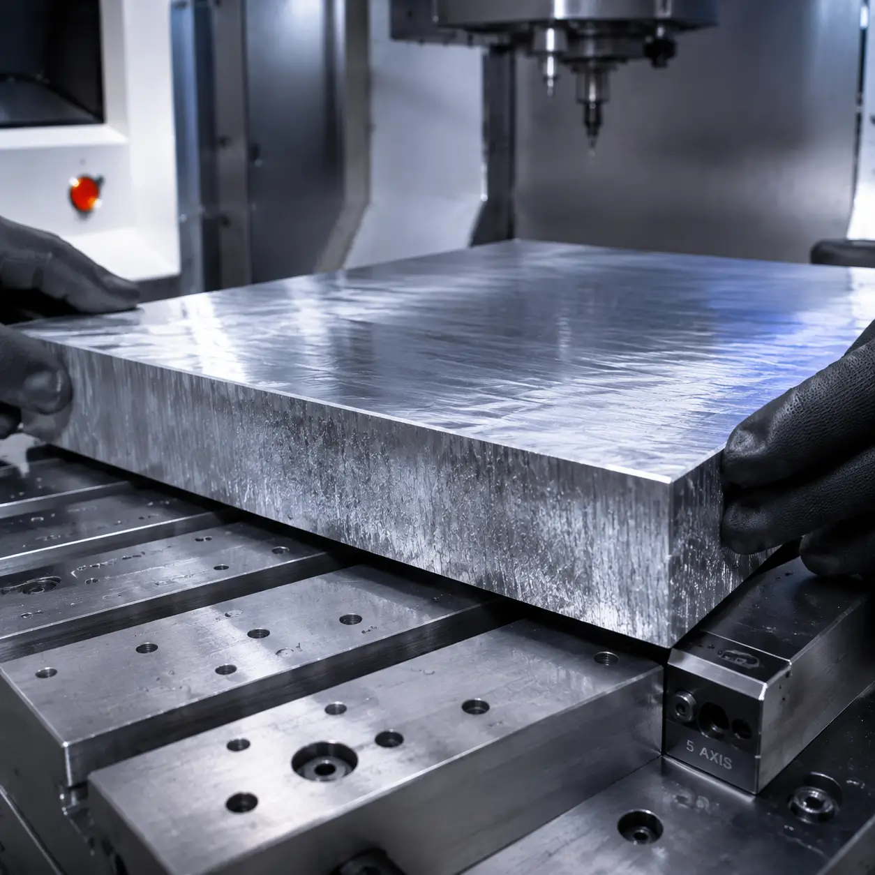
The Thick-Section Quench Sensitivity Failure Mechanism
When heat treating thick 7075 plate stock, the cooling rate during water quenching drops rapidly from the outer surface to the core. In plate thicknesses above 50mm, the core cooling rate falls below the critical threshold required to maintain the alloying elements (Zinc, Magnesium, Copper) in supersaturated solid solution. This creates coarse intermetallic precipitates at the grain boundaries, leading to:
· Severe loss of core mechanical yield strength (often dropping by more than 15% to 20% compared to surface values).
· Rapid degradation of fracture toughness in the short-transverse (ST) direction.
· Extreme susceptibility to stress-corrosion cracking (SCC) when sustained tensile loads act perpendicular to the rolling plane in humid or marine environments.
Metallurgical Resolution via Zirconium Stabilization
Developed specifically to eliminate quench sensitivity while preserving ultra-high mechanical strength, 7050 aerospace aluminum modifies the Al-Zn-Mg-Cu quaternary system. By replacing Chromium with Zirconium as the primary grain-refining dispersoid former, 7050 maintains uniform mechanical properties across plates up to 150mm (6.0 inches) thick.
For aerospace structural engineers designing bulkhead frames, wing spar caps, missile fuselage rings, and landing gear support beams, 7050 aluminum CNC machining provides the static strength of 7000-series alloys with the fracture toughness and SCC resistance demanded by modern aerospace quality standards.
Operational Floor Realities at Dazao Machinery
Treating 7050-T7451 aluminum as an everyday alloy like 6061-T6 results in immediate scrap parts, broken carbide tooling, and dimensional non-conformances. Understanding the nuances of aluminum CNC machining processes has highlighted specific shop-floor realities:
1. High Raw Material Costs: The raw billet cost of aerospace-certified 7050-T7451 per kilogram is roughly 2.8 to 3.8 times that of commercial 6061-T6. Scrapping a part at 90% completion due to tool deflection or late-stage thermal distortion causes substantial financial loss.
2. High Material Removal Ratios: High-performance structural airframe components are frequently pocketed out from solid billets, with final-to-raw mass ratios (buy-to-fly ratio) ranging from 1:8 to 1:15. Removing 85% to 92% of the stock volume releases internal stresses that easily warp thin-walled parts.
3. Severe Chemical Sensitivities: The elevated copper level in 7050 (up to 2.6%) alters the anodizing response compared to low-copper alloys, demanding precise post-machining chemical processing controls to prevent surface pitting and out-of-spec bores.
Metallurgy, Chemical Composition, and Temper Selection: 7050-T7451 vs T7651
Understanding the performance of 7050 aluminum CNC parts requires inspecting the underlying metallurgy. The alloy belongs to the Al-Zn-Mg-Cu family, where precipitation hardening of the MgZn2 (eta and eta-prime) phases provides maximum yield strength.
Chemical Composition Breakdown
|
Element |
7050 Weight Percentage (%) |
7075 Weight Percentage (%) |
6061 Weight Percentage (%) |
Primary Metallurgical Function in 7050 |
|
Zinc (Zn) |
5.70 - 6.70 |
5.10 - 6.10 |
0.25 max |
Forms primary hardening precipitates (MgZn2) |
|
Magnesium (Mg) |
1.90 - 2.60 |
2.10 - 2.90 |
0.80 - 1.20 |
Pairs with Zn to drive precipitation kinetics |
|
Copper (Cu) |
2.00 - 2.60 |
1.20 - 2.00 |
0.15 - 0.40 |
Increases strength; alters precipitate-matrix potential |
|
Zirconium (Zr) |
0.08 - 0.15 |
0.05 max |
None |
Forms fine Al3Zr dispersoids; prevents recrystallization |
|
Chromium (Cr) |
0.04 max |
0.18 - 0.28 |
0.04 - 0.35 |
Deliberately restricted to eliminate quench sensitivity |
|
Iron (Fe) |
0.15 max |
0.50 max |
0.70 max |
Impurity phase; strictly limited to protect fracture toughness |
|
Silicon (Si) |
0.12 max |
0.40 max |
0.40 - 0.80 |
Impurity phase; restricted to prevent brittle constituent phases |
|
Titanium (Ti) |
0.06 max |
0.20 max |
0.15 max |
Ingot grain refinement during initial casting |
|
Aluminum (Al) |
Balance |
Balance |
Balance |
Base matrix |
Zirconium Pinning Mechanics vs Chromium Additions
In conventional alloys, Chromium forms coarse E-phase dispersoids during homogenization. These particles nucleate heterogeneous precipitation of hardening phases along grain boundaries during slow water quenching. This depletes solute atoms inside the grains and reduces mechanical properties at the core of thick plates.
In 7050 aluminum plate machining, Chromium is replaced with 0.08% to 0.15% Zirconium. Zirconium forms coherent, spherical, ultra-fine Al3Zr dispersoids (10 nm to 30 nm in diameter). These particles:
· Strongly pin grain boundaries, preventing grain growth and recrystallization during hot rolling or forging.
· Do not act as nucleation sites for the MgZn2 phase during quenching.
· Lower the critical quench cooling rate to approximately 3 °C/s to 5 °C/s, enabling deep through-hardening in plates up to 150mm (6.0 inches) thick.
Temper Designation Analysis: 7050-T7451 vs 7050-T7651
Choosing between T7451 and T7651 directly dictates the operational threshold of finished components under mechanical, fatigue, and environmental loads.
7050-T7451 (Formerly Designated T73651)
· Heat Treatment Sequence: Solution heat-treated at 475°C, water quenched, controlled cold stretched 1.5% to 3.0% to relieve macro residual stresses, followed by a two-stage artificial overaging process.
· Mechanical & Corrosion Profile: Overaging intentionally transforms the coherent η′ phase into slightly coarser η (MgZn2) precipitates. This drops peak static yield strength by roughly 8% to 10% compared to peak-aged T6 conditions, but expands the spacing between grain boundary precipitates.
· Key Benefit: Raises the Stress Corrosion Cracking (SCC) threshold in the Short-Transverse (ST) orientation to 240 MPa to 280 MPa. Provides high plain-strain fracture toughness (KIc≈32 to 38 MPa⋅m1/2).
· Primary Use Case: Thick structural CNC components, high-load aircraft bulkheads, rib structures, and primary load-bearing aerospace fittings.
7050-T7651
· Heat Treatment Sequence: Solution heat-treated, quenched, stretched 1.5% to 3.0%, and stabilized with a modified intermediate artificial aging profile designed for exfoliation corrosion resistance without overaging as far as T7451.
· Mechanical & Corrosion Profile: Positioned between peak-strength T6 and maximum-toughness T7451. Yields approximately 5% higher tensile strength than T7451 while providing acceptable resistance to exfoliation corrosion.
· Primary Use Case: Upper wing skins, stringers, thin-to-medium plate structural extrusions, and external structural panels.
Engineering Property Comparison: 7050-T7451 vs 7075-T651 vs 6061-T6
When evaluating machinable aluminum grades, the mechanical dataset below illustrates the thick-section strength retention of 7050-T7451:
|
Engineering Property |
7050-T7451 (Plate, 75mm thk) |
7075-T651 (Plate, 75mm thk) |
6061-T6 (Plate, 75mm thk) |
Testing Standard / Method |
|
Ultimate Tensile Strength (UTS), L-Dir |
510 MPa (74.0 ksi) |
525 MPa (76.1 ksi) |
310 MPa (45.0 ksi) |
ASTM E8 |
|
Tensile Yield Strength (TYS), L-Dir |
440 MPa (63.8 ksi) |
455 MPa (66.0 ksi) |
275 MPa (39.9 ksi) |
ASTM E8 |
|
Core Yield Strength (ST-Dir, 100mm Plate) |
405 MPa (58.7 ksi) |
335 MPa (48.6 ksi) |
240 MPa (34.8 ksi) |
ASTM E8 |
|
Elongation at Break (%), L-Dir |
11.0% |
9.0% |
12.0% |
ASTM E8 |
|
Elongation at Break (%), ST-Dir |
4.5% to 6.0% |
1.5% to 2.5% |
8.0% |
ASTM E8 |
|
Modulus of Elasticity (E) |
71.7 GPa (10.4 Msi) |
71.0 GPa (10.3 Msi) |
68.9 GPa (10.0 Msi) |
ASTM E111 |
|
Fracture Toughness (KIc, L-T Dir) |
35.0 MPa·m½ (31.8 ksi·in½) |
26.0 MPa·m½ (23.6 ksi·in½) |
29.0 MPa·m½ (26.4 ksi·in½) |
ASTM E399 |
|
Fracture Toughness (KIc, S-T Dir) |
25.0 MPa·m½ (22.7 ksi·in½) |
18.0 MPa·m½ (16.4 ksi·in½) |
24.0 MPa·m½ (21.8 ksi·in½) |
ASTM E399 |
|
SCC Threshold Resistance (ST-Dir) |
> 240 MPa (34.8 ksi) |
< 70 MPa (10.1 ksi) |
> 200 MPa (29.0 ksi) |
ASTM G47 |
|
Electrical Conductivity |
38.0% to 43.0% IACS |
32.0% to 34.0% IACS |
40.0% to 43.5% IACS |
ASTM E1004 |
|
Brinell Hardness (HBW, 500kg / 10mm) |
140 - 150 HBW |
145 - 155 HBW |
95 - 100 HBW |
ASTM E10 |
|
Machinability Index (Al6012 = 100%) |
75% |
70% |
85% |
Production Empirical |
|
Relative Raw Material Cost Factor |
3.0x - 3.8x |
2.0x - 2.5x |
1.0x (Baseline) |
Dazao Procurement Data |
Practical Machining Pitfalls: Three Critical Engineering Challenges
Real precision CNC manufacturing on high-load structural parts involves complex physical phenomena that must be accounted for on the shop floor.

The Thick-Plate Core Property Gradient and Anisotropy Trap
The Physical Mechanism
While the Zirconium content in 7050-T7451 aluminum mitigates quench sensitivity, it does not eliminate the physical laws of thermal conduction. In a 120mm or 150mm thick plate, the cooling rate at the centerline during quenching remains lower than at the surface.
Furthermore, the mechanical reduction ratio during rolling imparts grain elongation along the rolling direction (Longitudinal, L), secondary flattening along the width (Long-Transverse, LT), and minimal deformation across the thickness (Short-Transverse, ST).
When an engineering drawing calls out high-load pocketing features deep into the centerline of a thick 7050 plate, the actual machined core features exhibit:
· A 10% to 15% reduction in tensile yield strength relative to surface callouts.
· An elongation drop to as low as 4.0% to 5.5% in the ST-direction.
· Altered chip formation behavior during 7050 aluminum milling, showing increased micro-chipping tendencies on cutting tool corners when machining across ST grain boundaries.
Dazao Shop-Floor Failure & Resolution Case Study
· Failure Incident: A customer ordered an aerospace actuator bracket machined out of a 130mm thick 7050-T7451 billet. The primary mounting lug was nested precisely at the central plane of the raw block. During functional multi-axis load testing, the lug experienced micro-cracking at 82% of its calculated static limit load. The failure plane propagated directly along the short-transverse grain boundary.
· Root Cause Analysis: Dynamic shear stress was acting perpendicular to the ST grain alignment at the plate thermal core, where yield strength and fracture toughness were lower than nominal catalog values.
· The Engineering Fix:
1. Dazao modified the 5-axis CNC machining billet nesting layout. By reorienting the raw stock along the primary tensile vector, the critical lug loaded the L-grain direction instead of the ST-direction.
2. Mandated ultrasonic testing per AMS 2631 Class AA prior to machining to verify that no centerline micro-porosity existed.
3. Introduced an eddy-current electrical conductivity verification step across the exposed core pockets. Conductivity readings were held strictly between 38.5% and 42.0% IACS, confirming that overaging and precipitate distribution met structural criteria.
Asymmetric Residual Stress Release in Deep Pocket Milling
The Physical Mechanism
Engineers often assume that because 7050 aluminum plate machining utilizes pre-stretched material (1.5% to 3.0% permanent plastic set via stretching), the raw stock is free of internal residual stresses.
The stretching process establishes a macro-mechanical stress equilibrium: compressive residual stresses near the outer rolling skins balance tensile residual stresses deep in the plate core.
When a CNC mill cuts away 80% of the material from a single side to form a deep aerospace pocket, this balance is broken. As the compressive skin is removed, the tensile forces at the core resolve into a bending moment. When unclamped, this moment causes immediate elastic spring-back and part distortion.

Dazao Shop-Floor Failure & Resolution Case Study
Failure Incident: A thin-walled radar chassis base plate (overall dimensions: 580mm x 320mm x 22mm, with 1.5mm wall ribs and a 2.0mm bottom floor) was rough machined and finished in a single setup from a 50mm thick 7050-T7451 billet. Upon releasing the hydraulic vise clamps, the part exhibited a 1.85mm diagonal bow, completely violating the required 0.05mm flatness tolerance.
Dazao Standard Operating Procedure (SOP) for Thin-Wall 7050 Distortion Mitigation:
1. Symmetrical Roughing Strategy: Never rough cut a deep pocket to final depth in a single setup. Machine 50% of the stock depth on Side A, invert the part, rough 50% on Side B, and repeat incrementally. This removes equal amounts of the compressive skin layer from both faces, balancing residual stress gradients.
2. Thermal Stabilization Soak: For high-precision parts with wall thicknesses below 2.0mm, transfer rough-machined blanks (with 2.0mm to 3.0mm stock remaining) to an air-circulating oven. Soak at 120°C (248°F) for 4 hours, followed by slow air cooling. This reduces cutting-induced residual micro-stresses without degrading the T7451 temper.
3. Semi-Finishing Stress Relief Cuts: Machine all surfaces to within 0.3mm of final dimension using light radial depths of cut (ae<0.1×D).
4. Low-Stress Vacuum and Matrix Fixturing: For the final finishing pass, replace mechanical edge vices and toe clamps with custom vacuum chucks integrated with sacrificial wax or low-melting point alloy supports. This avoids mechanical clamping strains during finishing.
The High Copper Content Chemical Pitfall in Surface Passivation
The Physical & Electrochemical Mechanism
Alloy 7050 contains a nominal 2.0% to 2.6% Copper by weight. While this high copper content provides mechanical strength through fine precipitate formation, it complicates electrochemical surface finishing.
During standard Type II (Sulfuric Acid Anodizing) or Type III (Hardcoat Anodizing per MIL-A-8625), copper-rich phases do not form stable anodic aluminum oxides. Instead:
· Copper atoms dissolve into the acid bath, creating localized micro-galvanic cells.
· These micro-cells disrupt the growth of ordered hexagonal alumina pores (Al2O3).
· High localized currents form at copper-rich sites, leading to localized burning, surface pitting, and powdery, soft coatings that fail standard taber abrasion resistance tests.
· On cosmetic black or clear anodized parts, 7050 exhibits an uneven yellow or bronze cast.

Dazao Shop-Floor Failure & Resolution Case Study
· Failure Incident: A batch of 150 precision CNC-turned and milled 7050 hydraulic valve manifolds was processed for MIL-A-8625 Type III, Class 1 Hardcoat Anodizing (50µm target thickness) at an outside vendor using standard 6061 parameters. The result was catastrophic: internal spool-valve bores sized to ∅25.000mm±0.005mm experienced localized electrical burning and severe pitting, increasing the bore diameters out of tolerance to 25.035mm and ruining the entire production run.
Dazao Chemistry Control Protocol for 7050 Aluminum:
1. Strictly Forbid Aggressive Caustic Soda Etching: Standard sodium hydroxide (NaOH) etching aggressively removes surface aluminum while leaving an insoluble dark copper smut that accelerates galvanic burning in the anodizing tank. Dazao uses an inhibited, non-etching mild alkaline cleaner followed by a brief immersion in a nitric acid bath containing ammonium bifluoride (NH4HF2) to dissolve both copper and silicon surface residues.
2. Pulse-Current Low-Temperature Anodizing: For Type III hardcoating on 7050, the acid bath temperature is held strictly at 0°C to 2°C (32°F to 35.6°F). A pulse-rectified power supply gradually ramps voltage, keeping peak current densities around 1.5 to 2.0 A/dm². This cold, pulsed profile prevents localized thermal runaway around copper-rich grain boundaries.
3. Recommend Chemical Conversion Over Hardcoat: When dimensional tolerances are tighter than ±0.010mm and wear resistance is not the primary requirement, Dazao guides clients toward MIL-DTL-5541 Type II, Class 1A or Class 3 Chemical Conversion Coatings (Alodine / Chromate Conversion). This process deposits an ultra-thin (under 1.0µm) passivation layer without geometric dimensional growth or galvanic pitting risks.
CNC Machining Strategy: Milling, Turning, and Tooling Protocols for 7050 Aluminum
Achieving repeatable tolerances below ±0.025mm on complex 7050-T7451 aluminum components requires managing cutting dynamics, chip evacuation, and cutting-edge geometry. Due to the high zinc and copper content, 7050 exhibits higher shear strength and greater tool friction than standard alloys, demanding rigid tooling and optimized toolpaths.

Tooling Substrates, Flute Geometry, and Coatings
Using generic aluminum tooling on 7050 workpieces leads to premature tool wear, built-up edge (BUE), and chatter marks. The following tooling specifications are verified standards across the Dazao production floor:
· Tool Substrate: Sub-micron grain tungsten carbide (0.5µm to 0.8µm grain size) with 6% to 8% cobalt binder content. This provides high transverse rupture strength to withstand intermittent cutting loads without edge chipping.
· Tool Coating: Uncoated micro-polished carbide or Diamond-Like Carbon (DLC) coating with a friction coefficient below 0.10 against aluminum. Titanium-based coatings (TiN, TiCN, TiAlN) are strictly forbidden because titanium has a high chemical affinity for aluminum at temperatures above 350°C, causing chip welding.
· Rake and Helix Angles: High positive radial rake angle (15° to 20°) and an axial rake angle of 12° to 15° to cleanly shear 7050 chips. Unequal flute spacing with variable helix geometry (38°/41°) breaks regenerative vibration frequencies during deep cavity milling.
· Flute Surface Finish: Mirror-polished flutes with a surface roughness of Ra<0.05μm to prevent chip adhesion in deep pocket operations.
Speeds, Feeds, and Cutting Parameters Matrix
When deploying 5-axis CNC machining services, the parameters below apply to rigid machining centers running high-pressure emulsion:
|
Machining Operation |
Tool Diameter (mm) |
Cutting Speed, Vc(m/min) |
Spindle Speed, n (RPM) |
Feed per Tooth, fz(mm/tooth) |
Axial Depth, ap (mm) |
Radial Depth, ae (mm) |
Tooling Specification |
|
High-Efficiency Roughing (Trochoidal) |
Ø16.0 |
450 - 650 |
9,000 - 13,000 |
0.18 - 0.25 |
Up to 32.0 (2.0xD) |
1.6 - 2.4 (10-15% D) |
3-Flute DLC Variable Helix |
|
Heavy Face Milling |
Ø63.0 (Indexable) |
600 - 900 |
3,000 - 4,500 |
0.15 - 0.22 |
2.5 - 4.0 |
45.0 - 50.0 |
Polished Octagonal Inserts |
|
Semi-Finish Wall Contouring |
Ø12.0 |
400 - 550 |
10,500 - 14,500 |
0.08 - 0.12 |
12.0 - 24.0 |
0.30 - 0.50 |
3-Flute Uncoated Carbide |
|
High-Speed Mirror Finishing |
Ø10.0 |
500 - 750 |
16,000 - 24,000 |
0.04 - 0.08 |
5.0 - 10.0 |
0.05 - 0.15 |
3-Flute Mirror Polished |
|
Deep Hole Drilling (L/D = 8) |
Ø8.0 |
120 - 160 |
4,800 - 6,300 |
0.14 - 0.20 mm/rev |
Through Hole |
Full Diameter |
Through-Spindle Coolant Drill |
|
Rigid Tapping (Blind Hole) |
M8x1.25 |
20 - 35 |
800 - 1,400 |
1.25 mm/pitch |
Up to 16.0 |
Full Thread |
Spiral Flute Modified Bottoming |
|
Precision External Turning |
CNMG 120408 |
350 - 500 |
Variable CSS |
0.15 - 0.30 mm/rev |
1.5 - 3.0 |
N/A |
High-Luster Uncoated Carbide |
High-Efficiency Trochoidal Milling and Chip Thinning Mechanics
Conventional full-slot milling creates an abrupt tool engagement angle of 180°, which generates high thermal shock and radial tool deflection in 7050. This deflection leads to taper errors in deep-walled structures.

Dazao utilizes dynamic trochoidal toolpaths with constant tool engagement angles (35∘ to 45∘). To maintain a constant uncut chip thickness (hex) when radial engagement (ae) drops below 20% of tool diameter (D), the programmed feed per tooth (fz) must be mathematically compensated:
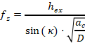
Where:
· hex = Target chip thickness (typically 0.12mm to 0.18mm for roughing 7050)
· κ = Tool cutting edge angle (90° for square shoulder end mills)
· ae = Radial depth of cut
· D = Cutter diameter
By maintaining high cutting velocity (Vc>500 m/min) and low radial engagement (ae/D=0.10), cutting heat is transferred directly into the escaping chips rather than penetrating the workpiece. This prevents thermal growth and avoids inducing tensile residual stresses into the raw material.
High-Pressure Coolant and Lubrication Control
Machining 7050-T7451 aluminum requires strict lubrication and cooling controls to prevent chip re-cutting and surface degradation:
1. High-Pressure Coolant (HPC): Machine tools must deliver water-soluble synthetic or semi-synthetic emulsion through the spindle at minimum 70 bar (1,015 PSI). High-pressure jets directed straight down the tool flutes fragment stringy chips and clear them instantly from deep pockets.
2. Coolant Concentration and pH Levels: Emulsion concentration must be maintained between 8.0% and 10.0%. Concentrations below 7% lead to aluminum smearing on cutting edges, while concentration levels above 12% cause staining on the high-copper surface. Coolant pH must be maintained within the 8.8 to 9.2 range to eliminate intergranular corrosion during multi-day production runs.
Tolerance Capability, Metrology, and Quality Verification for Aerospace Parts
Precision custom 7050 aluminum parts require rigorous dimensional and metallurgical verification across every phase of production.
Dimensional Tolerance Capabilities in Production
|
Geometric Feature |
Standard Machining Tolerance |
Precision Aerospace Tolerance |
Critical Processing Condition |
|
Linear Dimensions (≤100mm) |
±0.025 mm (±0.0010 In) |
±0.008 mm (±0.0003 In) |
Multi-pass finishing with micro-grain carbide |
|
Linear Dimensions (>300mm) |
±0.050 mm (±0.0020 In) |
±0.018 mm (±0.0007 In) |
Thermally compensated machine scales |
|
Hole Diameter (Boring / Reaming) |
±0.012 mm (±0.0005 In) |
±0.005 mm (±0.0002 In) |
Fine boring heads with diamond inserts |
|
True Position (Hole Patterns) |
0.035 mm True Position |
0.010 mm True Position |
Single-setup 5-axis continuous indexing |
|
Flatness (over 500mm×500mm) |
0.080 mm Flatness |
0.025 mm Flatness |
Balanced stress-relief roughing + vacuum fixture |
|
Surface Finish (Ra, Milled Faces) |
Ra 0.8μm (32μIn) |
Ra 0.2μm (8μIn) |
Polished PCD or DLC wiper radius tooling |
Thermal Drift Management and Cleanroom Metrology
Aluminum 7050 has a high thermal expansion coefficient:
α=23.5×10⁻⁶ K−1(20∘C to 100∘C)
On a 600mm structural aerospace component, a temperature fluctuation of just 3.0°C induces an unconstrained dimensional expansion of:
ΔL=L⋅α⋅ΔT=600 mm×(23.5×10−6 K−1)×3.0 K=0.0423 mm
This thermal expansion consumes more than 80% of a standard ±0.025mm drawing tolerance band.
To eliminate thermal metrology errors, Dazao enforces:
1. Climate-Controlled Machining Environments: Production floors are maintained at 20°C ± 1.0°C (68°F ± 1.8°F).
2. 24-Hour Metrology Stabilization: Machined components must rest inside the CMM inspection laboratory (maintained at 20°C ± 0.5°C) for at least 24 hours prior to final dimension sign-off.
3. Dynamic CMM Temperature Compensation: Coordinate Measuring Machines utilize real-time workpiece surface contact temperature sensors to offset microscopic thermal drift.
Non-Destructive Testing (NDT) & Aerospace Compliance
Every batch of 7050 aerospace components manufactured at Dazao undergoes non-destructive evaluation to verify internal integrity and temper consistency:
· Raw Material Ultrasonic Inspection (AMS 2631 Class AA): Raw billets are scanned to verify the absence of centerline voids, micro-porosity, and inclusions larger than 1.2mm equivalent flat-bottom hole response.
· Electrical Conductivity Testing (ASTM E1004): Eddy-current conductivity testing verifies temper status. Readings for 7050-T7451 must fall strictly within 38.0% to 43.0% IACS. Any reading below 38.0% IACS indicates an under-aged condition (insufficient SCC resistance), while readings above 43.5% IACS signal over-aging (unacceptable yield strength loss).
· Fluorescent Penetrant Inspection (FPI per ASTM E1417 Level 3 or 4): Completed CNC parts are subjected to high-sensitivity fluorescent liquid penetrant inspection to detect micro-cracks, tear defects, or boundary discontinuities in high-stress fillets.
Surface Finishing, Anodizing Protocols, and Shot Peening
Post-machining surface treatments on 7050 aluminum must protect against environmental corrosion without degrading mechanical fatigue performance.

Surface Treatment Comparison for High-Strength Alloys
When selecting MIL-A-8625 Type III hardcoat anodizing, balancing corrosion protection against fatigue degradation is critical:
|
Finishing Process |
Standard / Specification |
Layer Thickness / Depth |
Impact on Fatigue Life |
Dimensional Compensation on CNC Drawing |
Corrosion Resistance (ASTM B117 Salt Spray) |
|
Chemical Conversion (Chromate/TCP) |
MIL-DTL-5541 Type II, Class 1A |
0.2µm - 0.8µm |
Neutral (0% change) |
Zero offset required (<1.0μm) |
168 - 336 Hours |
|
Low-Resistance Chem Film |
MIL-DTL-5541 Type II, Class 3 |
0.1µm - 0.3µm |
Neutral (0% change) |
Zero offset required (<0.5μm) |
168 Hours |
|
Sulfuric Acid Anodize (Type II) |
MIL-A-8625 Type II, Class 1/2 |
8.0µm - 15.0µm |
Moderate loss (-10% to -15%) |
Subtract 50% of thickness per surface side |
336 Hours |
|
Hardcoat Anodize (Type III) |
MIL-A-8625 Type III, Class 1 |
25.0µm - 50.0µm |
High reduction (-25% to -40%) |
Pre-machine bore IDs +0.025mm to +0.050mm |
1,000+ Hours |
|
Precision Controlled Shot Peening |
AMS 2430 / AMS-S-13165 |
0.15mm - 0.35mm plastically deformed depth |
High gain (+30% to +50%) |
Surface roughness increases ( Ra 1.6 to 3.2μm) |
Indirectly improves SCC resistance |
The Fatigue Life Restoration Role of Controlled Shot Peening
Hardcoat anodizing creates microscopic surface fissures in the brittle aluminum oxide layer, reducing baseline fatigue limits by 25% to 40%. For dynamic structural components, Dazao integrates controlled shot peening per AMS 2430:
· Mechanism: Bombarding the machined surface with high-hardness cast steel shot (ASH 170 to 230) or ceramic beads under controlled Almen intensity (typically 0.008A to 0.012A at 200% coverage) induces a deep compressive residual stress layer (-300 MPa to -450 MPa) up to 0.25mm beneath the surface.
· Engineering Impact: This compressive barrier prevents micro-cracks from initiating at surface tool marks, restoring fatigue limits and raising the stress corrosion cracking threshold beyond base material values.
Aerospace, Defense, and Extreme-Duty Industrial Applications
The mechanical stability and stress-corrosion immunity of precision 7050 aerospace components make it the engineering alloy of choice across high-reliability industries.

Commercial & Military Aircraft Primary Airframes
In modern aircraft design alongside 2024 aluminum aerospace machining, 7050 is the premier choice for heavy load-bearing structural members:
· Main Bulkhead Frames and Ribs: Monolithic components pocketed out from 120mm to 150mm thick 7050-T7451 plate billets. Replacing multi-piece riveted sheet-metal assemblies with single-piece 7050 hog-outs reduces total airframe weight while eliminating fatigue-prone rivet joints.
· Wing Spar Caps and Landing Gear Support Trunnions: Highly loaded structural members subject to continuous bending moments, where the short-transverse stress corrosion threshold of 7050-T7451 prevents catastrophic failure from trapped runway de-icing salts and humid air.
Tactical Missiles and Launch Vehicles
· Guidance Section Adapter Rings: Precision turned and milled rings with tight circularity and runout tolerances (within 0.015mm), capable of withstanding extreme axial thrust loads during stage separation.
· Aerodynamic Control Fin Actuation Shafts: 7050-T7451 parts turned and 5-axis milled to deliver high torsional shear strength and high stiffness during supersonic maneuvers.
High-Speed Semiconductor Handling Mechanisms
· Dynamic Pick-and-Place Robotic End-Effectors: High-speed automation arms operating with accelerations exceeding 15G. Alloy 6061-T6 suffers from micro-flexure and fatigue failure under these cyclic loads, while 7050-T7451 maintains geometric stiffness and extends operational fatigue life across millions of continuous cycles.
Cost Drivers, DFM Guidelines, and Procurement Strategy for 7050 Parts
Transparent Breakdown of 7050 Machining Cost Drivers
DFM Optimization Rules for Cost Reduction
Engaging in an early DFM engineering review reduces machine cycle times, cuts tool wear, and lowers the risk of distortion-induced scrap:
· Optimize Internal Corner Radii: Designing internal corner radii equal to standard tool radii forces the CNC tool to stop and turn at 90°, spiking tool engagement, inducing chatter, and requiring manual feed rate reductions. Specifying an internal radius at least 20% to 25% larger than the milling cutter radius (e.g., specifying R7.5mm for a Ø12mm cutter) allows smooth, continuous trochoidal circular interpolation without slowing spindle cycle times.
· Standardize Wall and Floor Thicknesses: Thin standing ribs under 1.0mm require multiple light semi-finishing passes to prevent wall deflection and chatter. Increasing minimum wall thickness to 1.5mm to 2.0mm cuts machining time on thin-ribbed components by up to 45%.
· Avoid Unnecessary Pocket Depth Ratios: Limit pocket depths to less than four times the cutter diameter (Depth≤4×D). Pocket depths exceeding 5xD require extended-reach toolholders, which force a 60% reduction in chip removal rates to suppress harmonic chatter.
Dazao Manufacturing Integrity & Supply Chain Control
Partnering with Xiamen Dazao Machinery for your high-strength aluminum manufacturing needs gives you access to complete quality control and engineering support:
· Certified Aerospace Material Sourcing: Direct procurement of fully traceable raw plate stock complying with AMS 4050, AMS 4201, and AMS-QQ-A-250/12, accompanied by full Mill Test Reports (MTR).
· Multi-Axis CNC Capabilities: Fleet of modern 3-axis, 4-axis, and simultaneous 5-axis machining centers with 20,000 RPM high-torque spindles and 70-bar through-spindle cooling systems.
· ISO 9001:2015 and IATF 16949:2016 Certified Quality Operations: In-house climate-controlled metrology lab equipped with CMM, optical shaft scanners, eddy-current conductivity meters, and complete non-destructive testing infrastructure.
FAQs
01.How to eliminate part warpage when milling deep pockets in 7050-T7451?
02.Why do 7050 parts turn bronze or develop dark spots during sulfuric anodizing?
03.What causes severe tap breakage and thread binding in 7050 blind holes?
04.Why do TiAlN coated end mills fail prematurely when roughing 7050 aluminum?
05.What is the engineering difference between 7050-T7451 and the older T73651 temper designation?
06.How to avoid short-transverse (ST) micro-cracking in deep-pocket 7050 components?





