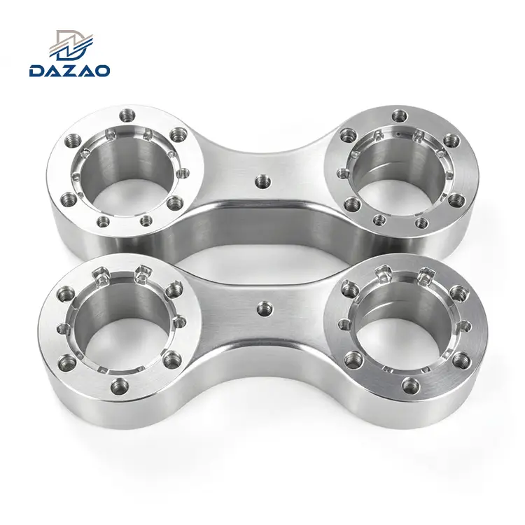
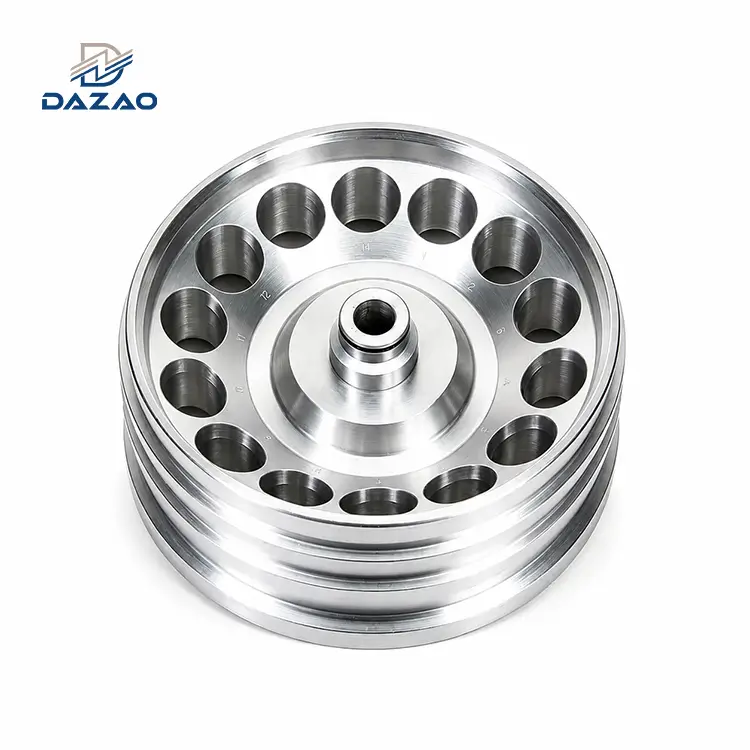
While 5052 aluminum provides superior corrosion resistance in marine and chemical environments compared to 6061-T6, its high ductility (12% to 18% elongation) creates severe machining challenges, including Built-Up Edge (BUE), long stringy chips, edge burrs, and stress-induced part warping.
Achieving tight tolerances (±0.0005 in / ±0.012 mm) and Ra 0.8 µm surface finishes requires highly specific tool geometry (20° positive rake angles, polished flutes), high-pressure coolant (>70 bar), and structured multi-pass roughing/stress-relief routines.

Why 5052 Aluminum CNC Machining Is Frequently Misunderstood in Engineering Design?
In precision manufacturing, 5052 aluminum cnc machining is frequently mischaracterized. Design engineers often categorize 5052 aluminum primarily as a sheet metal alloy reserved for stamping, hydraulic tubing, or simple press-brake bending. When high-precision milled or turned components are needed, CAD models default to 6061-T6 or 7075-T6.
This default choice creates significant engineering compromises.
While 6061-T6 yields short chips and machines cleanly, its long-term performance degrades rapidly in chloride-rich environments, marine exposure, or high-humidity industrial atmospheres. Applying heavy anodizing coatings to 6061 adds cost and alters dimensional tolerances. If you are reviewing general aluminum machining options, consult our complete aluminum CNC machining guide for foundational material comparisons.
In contrast, custom 5052 aluminum parts possess inherent resistance to saltwater corrosion, high fatigue strength, and superior cold-workability. These characteristics make 5052 essential for:
· Sealed Marine Electronics: Submersible housings, radar mounts, and underwater sensor brackets requiring prolonged exposure to salt spray without surface pitting.
· Automotive & EV Battery Assemblies: Lightweight fluid-cooled cold plates, battery module busbar covers, and structural brackets where vibration resistance and post-machining weldability are essential.
· Medical & Industrial Enclosures: Sealed control boxes, pneumatic valve manifolds, and chemical fluid transfer housings that undergo aggressive washdown routines.
Demand for 5052 aluminum machining has increased significantly. Modern engineering demands multi-functional parts-components that require intricate CNC-milled features (such as O-ring grooves, threaded mounting ports, and deep pocketing) while maintaining raw material corrosion resistance and structural ductility.
Executing 5052 aluminum milling or 5052 aluminum turning requires a distinct approach compared to heat-treatable alloys. 5052 is a non-heat-treatable, strain-hardened magnesium-alloyed aluminum. Attempting to machine it using standard 6061 feeds, speeds, and tool geometries results in severe material tearing, rapid tool gumming, excessive burr generation, and post-clamping dimensional distortion.
Since 2000, Xiamen Dazao Machinery has manufactured precision components in an ISO9001:2015 and IATF16949:2016 certified facility. Operating advanced 3-, 4-, and 5-axis CNC machining centers, our engineering team has developed validated parameters to solve the machining challenges inherent to 5052 aluminum. This technical guide outlines the material dynamics, machining protocols, and DFM strategies required to produce reliable 5052 aluminum components.
Deconstructing Al 5052: Microstructure, Tempers (H32 vs. H34), and Corrosion Kinetics
Selecting 5052 for a precision CNC component requires an understanding of its metallurgical composition, work-hardening characteristics, and corrosion kinetics. For a broader perspective across all series, refer to our aluminum alloy grades selection guide.
Chemical Composition & Microstructural Phase Dynamics
The fundamental performance of 5052 aluminum stems from its chemical composition (ASTM B209 / AA5052 standards):
|
Element |
Weight Percentage (%) |
Metallurgical Function |
|
Magnesium (Mg) |
2.20 - 2.80 |
Primary solid-solution strengthening agent; enhances strain hardening and marine corrosion resistance. |
|
Chromium (Cr) |
0.15 - 0.35 |
Forms fine dispersoids (Al18Mg3Cr2); controls grain growth and improves resistance to stress corrosion cracking. |
|
Iron (Fe) |
Max 0.40 |
Impurity phase; forms insoluble Al3Fe intermetallics that negatively impact polishability and anodizing uniformity. |
|
Silicon (Si) |
Max 0.25 |
Impurity phase; combines with Fe to form Fe3SiAl12 micro-constituents. |
|
Copper (Cu) |
Max 0.10 |
Kept minimal to preserve high pitting corrosion resistance. |
|
Manganese (Mn) |
Max 0.10 |
Secondary grain refinement. |
|
Zinc (Zn) |
Max 0.10 |
Trace element limits. |
|
Other (Total) |
Max 0.15 |
Residual impurities. |
|
Aluminum (Al) |
Balance (~95.7 - 97.7) |
Base matrix. |
The alloy relies on solid-solution strengthening via Magnesium. Magnesium atoms distort the aluminum crystal lattice, creating localized strain fields that impede dislocation movement. This yields higher tensile strength than pure aluminum alloys (1000 series) without requiring precipitation hardening heat treatments (such as T6 aging).

Temper State Selection: 5052-H32 vs. 5052-H34
Because 5052 is non-heat-treatable, its mechanical properties are established through cold working (strain hardening) followed by thermal stabilization (the "H" temper designations). Choosing between tempers directly impacts machinability and structural performance.
1. 5052-H32 Aluminum Machining (Strain Hardened and Stabilized – 1/4 Hard):
· Process: Cold rolled to target hardness, then thermally stabilized at low temperature to reduce internal stresses and stabilize mechanical properties over time.
· Mechanical Response: Yield strength ~193 MPa (28 ksi), Ultimate Tensile Strength ~228 MPa (33 ksi), Elongation 12% to 18%.
· Machining Behavior: Highly ductile. Tool contact creates plastic deformation before shearing occurs. Requires sharp cutting edges to cut cleanly without smearing. Ideal for complex 5052 aluminum enclosure machining where secondary forming or post-machining bending is required.
2. 5052-H34 Aluminum Machining (Strain Hardened and Stabilized – 1/2 Hard):
· Process: Subjects the raw stock to higher cold-reduction ratios prior to stabilization.
· Mechanical Response: Yield strength ~214 MPa (31 ksi), Ultimate Tensile Strength ~262 MPa (38 ksi), Elongation 8% to 14%.
· Machining Behavior: The higher yield-to-tensile ratio and reduced ductility make 5052 H34 aluminum machining cleaner than H32. The material produces slightly shorter chips and exhibits less edge burring. However, internal residual stresses are higher, requiring controlled stock removal routines to prevent part distortion.
Mechanical & Physical Property Data Matrix
The following parameters govern cutting force calculations, thermal dissipation strategies, and structural finite element analysis (FEA) for 5052 aluminum components:
|
Property Metric |
Standard Unit |
5052-O (Annealed) |
5052-H32 (1/4 Hard) |
5052-H34 (1/2 Hard) |
|
Density |
g/cm³ (lb/in³) |
2.68 (0.0968) |
2.68 (0.0968) |
2.68 (0.0968) |
|
Ultimate Tensile Strength |
MPa (ksi) |
193 (28) |
228 (33) |
262 (38) |
|
Yield Strength (0.2% offset) |
MPa (ksi) |
89 (13) |
193 (28) |
214 (31) |
|
Modulus of Elasticity (E) |
GPa (ksi × 10³) |
70.3 (10,200) |
70.3 (10,200) |
70.3 (10,200) |
|
Shear Strength |
MPa (ksi) |
124 (18) |
138 (20) |
145 (21) |
|
Fatigue Strength (5 × 10⁸ cycles) |
MPa (ksi) |
110 (16) |
117 (17) |
124 (18) |
|
Elongation at Break (50 mm gauge) |
% |
25% - 30% |
12% - 18% |
8% - 14% |
|
Brinell Hardness |
HBW (500 kg load) |
47 |
60 |
68 |
|
Thermal Conductivity |
W/m·K (BTU-in/hr-ft²-°F) |
138 (960) |
138 (960) |
138 (960) |
|
Coefficient of Thermal Expansion (α) |
µm/m-°C (20-100°C) |
23.8 |
23.8 |
23.8 |
|
Specific Heat Capacity |
J/g-°C (BTU/lb-°F) |
0.90 (0.215) |
0.90 (0.215) |
0.90 (0.215) |
|
Electrical Conductivity |
% IACS |
35% |
35% |
35% |
Corrosion Mechanics: Why 5052 Is the Primary Choice for Severe Environments
5052 is often chosen as a primary material for corrosion resistant aluminum parts due to its behavior in marine environments. When exposed to oxygen, aluminum instantly forms an amorphous passive aluminum oxide surface film (Al2O3). In heat-treatable alloys containing high copper or zinc concentrations (such as 2024 or 7075), intermetallic precipitates (θ-phase Al2Cu or η-phase MgZn2) create localized galvanic cells. These cells break down the oxide layer in the presence of chloride ions (Cl-), initiating pitting corrosion.
In 5052, Magnesium remains evenly dissolved within the solid-solution matrix or precipitates as microscopic Al3Mg2 phase particles along grain boundaries. The addition of Chromium (0.15% to 0.35%) stabilizes this microstructure and prevents intergranular attack.
· ASTM B117 Salt Spray Testing: Uncoated 5052 aluminum shows minimal pitting after 3,000+ hours of continuous salt fog exposure, whereas 6061-T6 exhibits visible surface oxidation and pitting within 500 to 800 hours under identical conditions.
· Pitting Potential (Epit): In a standard 3.5% NaCl solution, 5052 exhibits a significantly higher pitting potential than 2024 or 7075, making it an optimal material for subsea sensors, chemical processing, and marine hardware.
Engineering Benchmark: 5052 Aluminum vs. 6061 Aluminum Trade-Offs
When evaluating structural aluminum alloys, mechanical design engineers frequently debate 5052 aluminum vs 6061. For deeper analysis on the 6061 side, see our detailed 6061 aluminum CNC machining guide.
1. Mechanical Strength & Hardness vs. Ductility
· 6061-T6: Heat treating and artificial aging precipitate Mg2Si phases throughout the matrix, yielding a high yield strength (~276 MPa / 40 ksi) and high Brinell hardness (95 HBW). It resists structural deformation under heavy mechanical loads.
· 5052-H32: Possesses a lower yield strength (~193 MPa / 28 ksi) and lower hardness (60 HBW). However, its ultimate strain-to-failure (elongation up to 18%) is significantly higher than 6061-T6 (8% to 10%). Under impact loading or shock forces, 5052 absorbs energy through localized elastic-plastic deformation without catastrophic brittle cracking.
2. Machinability Metrics & Material Behavior Under Cutting Tool Shear
Machinability ratings are indexed against 2012-T3 aluminum (100%).
· 6061-T6 (Machinability Rating: ~80%): Behaves predictably during cutting operations. The tool edge shears the brittle, precipitation-hardened matrix efficiently, forming short, C-shaped chips that clear tool flutes smoothly.
· 5052-H32 (Machinability Rating: ~50%): High material ductility causes significant elastic-plastic deformation ahead of the cutting edge before shear failure occurs. This leads to continuous, ribbon-like chips that wrap around rotating spindles. The material tends to weld itself to the cutting tool edge (Built-Up Edge / BUE), causing micro-chipping on carbide flutes and poor surface finish.
3. Anodizing Response: Visual Aesthetics & Technical Performance
Engineers frequently assume all aluminum alloys anodize similarly. However, their chemical compositions yield distinctly different anodized surfaces:
· 6061-T6 Anodizing: Anodizes evenly, producing uniform Type II clear/color finishes and thick Type III hardcoat layers (>50 µm). The low Magnesium content yields a bright, uniform aesthetic finish suitable for visible consumer components.
· 5052 Anodizing Challenges: The 2.2% to 2.8% Magnesium content impacts anodic coating growth. During sulphuric acid anodizing, Magnesium dissolves preferentially, forming micro-porosities within the oxide structure. This often causes 5052 aluminum cnc parts to develop a cloudy, dull greyish haze or subtle color mottling, particularly with clear or bright color anodizing.
4. Cold Formability and Secondary Joining / Welding Operations
· 5052 Superiority: In applications combining CNC machining with sheet metal bending, deep drawing, or TIG/MIG welding, 5052 performs significantly better than 6061. 6061-T6 often cracks along tight bend radii unless annealed to the "O" temper. 5052-H32 supports tight 1t bend radii without cracking.
· Welding Performance: 5052 retains structural integrity across the Heat-Affected Zone (HAZ) post-welding. Conversely, 6061-T6 suffers significant strength reduction in the HAZ as heat disrupts the artificial aging precipitates, dropping yield strength by up to 40% to 50% unless the assembly undergoes solution heat treatment and re-aging.
Comparative Engineering Matrix: 5052 vs. 6061
|
Parameter / Metric |
5052-H32 Aluminum |
6061-T6 Aluminum |
Engineering Selection Driver |
|
Primary Alloy Class |
Non-Heat-Treatable (Al-Mg) |
Heat-Treatable (Al-Mg-Si) |
Base metallurgy and strain-hardening response. |
|
Yield Strength |
193 MPa (28 ksi) |
276 MPa (40 ksi) |
Use 6061 for higher mechanical load requirements. |
|
Elongation at Break |
12% - 18% |
8% - 10% |
Use 5052 for severe impact or cold-forming demands. |
|
Machinability Rating |
50% (Gummy, long chips) |
80% (Clean chip breaking) |
6061 reduces CNC cycle time and tooling costs. |
|
BUE Tendency |
High (Requires sharp, polished tools) |
Low-Moderate |
5052 requires specific coolant and tool rake strategies. |
|
Marine Corrosion Resistance |
Excellent (Zero pitting in Cl-) |
Moderate (Requires protective coatings) |
5052 is the standard for direct seawater immersion. |
|
Complex Weldability |
Superior (Minimal strength loss) |
Moderate (HAZ strength loss up to 50%) |
5052 is ideal for welded fluid/pressure assemblies. |
|
Deep Bending/Formability |
Excellent (1t radius capable) |
Poor (Prone to cracking in T6) |
Choose 5052 for combined machining and sheet metal parts. |
|
Clear Anodize Aesthetics |
Prone to hazy/cloudy finish |
Bright, highly uniform |
Use 6061 for high-visibility cosmetic housings. |
|
Raw Material Unit Cost |
Lower / Comparable to 6061 |
Baseline Benchmark |
Base material cost varies with market mill pricing. |
Eliminating Chip Entanglement, Burr Formation, and Springback Strain
The primary difficulties in 5052 aluminum cnc machining stem from its high ductility (12% to 18% elongation) and low yield-to-tensile ratio. During 5052 aluminum milling or 5052 aluminum turning (which can be outsourced via our custom CNC turning service), the cutting edge subjects the material to plastic strain before shear rupture occurs. This plastic strain creates three major machining failure modes: long stringy chips, heavy exit burrs, and elastic springback.
1. Chip Shear Dynamics & Built-Up Edge (BUE) Thermodynamics
In brittle or heat-treated alloys (e.g., 6061-T6), the shear angle φ remains large (φ ≈ 30° - 35°), producing small chip cross-sections that fracture under compression. In 5052-H32 aluminum machining, high material ductility depresses the shear plane angle (φ ≈ 18° - 22°).
The relationship governing shear angle (φ), rake angle (α), and friction angle (β) is expressed via Merchant's Force Circle:
Shear Angle Formula: φ = 45° + (α / 2) - (β / 2)
Because 5052 exhibits a high friction coefficient (μ = tan(β) ≈ 0.65 - 0.80) against uncoated carbide, the friction angle (β) increases, lowering the shear angle (φ). This increases the shear zone length, generating thick, continuous ribbon chips.
These continuous chips wrap around tool holders and CNC spindles, scoring finished part surfaces, obstructing coolant channels, and causing tool breakage.
Furthermore, under cutting temperatures between 200°C and 350°C, 5052 exhibits high chemical affinity for carbide tooling. Micro-welding occurs at the tool-chip interface, forming a Built-Up Edge (BUE). As the BUE cyclically forms and breaks away, it strips carbide grains from the tool edge and leaves torn, rough surfaces on the part (Ra > 3.2 µm).

2. Burr Formation Kinetics and High-Speed Deburring Protocols
When an end mill exits a 5052 aluminum component, the low yield strength allows material to bend plastically away from the tool edge rather than shearing cleanly. This leaves heavy exit burrs up to 0.5 mm thick. Standard automated deburring tools or tumbling media often fail to remove these burrs, merely folding the ductile metal back into the chamfer groove.
Xiamen Dazao Machinery Shop-Floor Protocol for Zero-Burr Edges:
· Climb Milling Strategy: Always utilize climb (down) milling (ae ≤ 0.3 × D). Climb milling establishes maximum chip thickness at initial tool entry and decreases chip thickness to zero at tool exit, reducing the exit material volume subject to plastic bending.
· 45° High-Rake Chamfer Geometry: Replace standard 90° deburring passes with specialized 45° single-lip polished chamfer tools operating at Vc ≥ 500 m/min and reduced feed per tooth (fz = 0.02 mm/tooth).
· Tool Path Overlap: Apply roll-around contour tool paths at sharp corners to ensure continuous cutting force vectors, preventing edge tearing at material transitions.
3. Residual Strain Management & Springback Control
Internal residual stresses in cold-rolled 5052 plate stock cause severe part deformation upon material removal. When machining asymmetric features (e.g., pocketing one side of a bracket), internal stress equilibrium is disrupted, causing the part to warp or bow once unclasped from the vise.
Dazao Machinery Stress Relief Protocol for Precision Parts:
1. Roughing Stage: Machine all surfaces to +1.0 mm stock allowance using high-feed tool paths.
2. Thermal / Vibrational Stress Relief: Submerge rough-machined parts in a controlled thermal stabilization cycle (220°C for 120 minutes) or apply sub-resonant vibrational stress relief to re-align internal crystalline dislocation networks.
3. Finishing Stage: Unclamp the part completely, re-seat it in custom soft jaws with light clamping pressure (< 1.5 MPa hydraulic holding force), and execute final finishing cuts (ap = 0.15 mm). This sequence yields flatnesses within ±0.015 mm across 500 mm span lengths.
Mitigating Thin-Wall Resonance & Deep Cavity Wall Chatter
Housing design for power electronics, subsea instrumentation, and EV modules requires deep internal pockets with wall thicknesses as thin as 0.8 mm to 1.2 mm. Executing 5052 aluminum enclosure machining via our precision CNC milling services introduces severe structural rigidity challenges.

The Physics of Thin-Wall Chatter & Resonance
The bending stiffness (K) of a cantilevered thin wall drops exponentially with wall thickness (t):
Bending Stiffness Formula: K ∝ (E × t³) / (12 × H³)
Where E is Elastic Modulus (70.3 GPa for 5052) and H is cavity height. Because 5052 has a lower modulus than steel (210 GPa), thin walls deflect under lateral cutting forces (Fc). When tool excitation frequency matches the wall's natural frequency (fn), severe chatter occurs, leaving visible wave patterns and failing surface roughness requirements (Ra > 6.3 µm).
Advanced Fixturing: Vacuum Adsorption & Soluble Support Media
Traditional mechanical vises apply concentrated compressive forces that permanently crush thin-walled 5052 enclosures. To process complex 5052 aluminum housing geometries, Xiamen Dazao Machinery deploys specialized fixturing strategies:
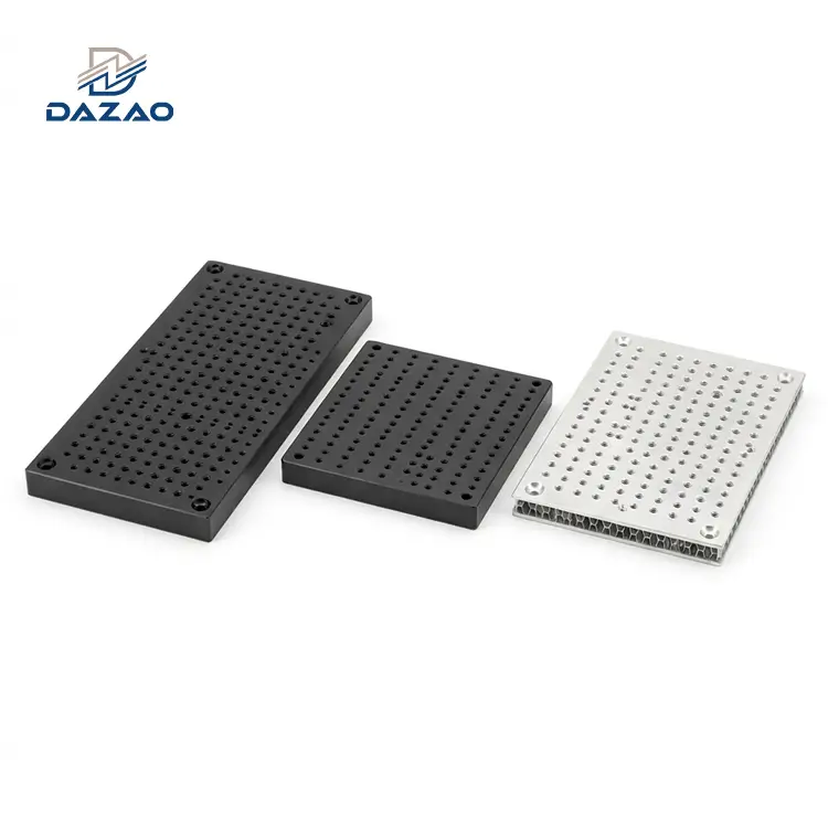
· Custom Vacuum Fixture Plates: CNC-milled aluminum fixture bases with integrated silicone seals and multi-channel vacuum manifolds operating at -85 kPa to -95 kPa absolute pressure. Vacuum fixturing distributes holding force uniformly across the base of thin-walled enclosures, eliminating physical clamp distortion and dampening chatter vibrations.
· Phase-Change Water-Soluble Support Media: For extremely deep cavities with wall-height-to-thickness ratios exceeding 15:1, cavity interiors are filled with a water-soluble rigid polymer compound prior to outer wall finishing passes. The solid polymer dampens chatter, supporting thin walls during machining. Once finished, the assembly is rinsed in warm water (60°C) to dissolve the compound cleanly.
Step-Milling Toolpath Optimization
Standard machining strategies rough out an entire pocket depth first, leaving thin walls unsupported during subsequent passes. For 5052 aluminum milling of deep enclosures, step-milling toolpaths maintain structural rigidity throughout the machining cycle:
1. Machine wall features in incremental depth steps (ΔZ = 2.0 mm to 3.0 mm).
2. Finish both inner and outer wall faces at step depth Zn while the bulk material below Zn acts as a rigid support anchor.
3. Step down to Zn+1 and repeat the localized finish pass, maintaining maximum structural stiffness at the active cutting zone.
Controlling Anodizing Discoloration, Cloudiness, and Grain Streaking
A major quality concern for B2B procurement heads sourcing 5052 aluminum cnc parts is visual color variation, cloudy patches, or streaking post-anodizing. Complete details on surface options are available through our precision aluminum anodizing services.

Metallurgical Factors Causing Anodizing Defects
Anodizing builds a porous aluminum oxide layer (Al2O3) via electrolytic oxidation:
Electrolytic Anodizing Reaction: 2Al + 3H₂O (+ Electrical Current) → Al₂O₃ + 6H⁺ + 6e⁻
The chemical composition of the substrate directly impacts film optical clarity and oxide layer density:
1. Magnesium Segregation: In low-grade 5052 plate material, Magnesium forms micro-segregation zones (Al3Mg2 phase). Under sulfuric acid anodizing bath conditions (15% to 20% H₂SO₄, 18°C to 21°C), these Magnesium concentrations dissolve at higher rates than the surrounding matrix. This produces microscopic voids within the oxide film that refract light irregularly, causing cloudy or yellowed patches.
2. Iron and Silicon Contamination: Impurity levels of Fe > 0.35% or Si > 0.20% form insoluble Al3Fe or Fe3SiAl12 intermetallic particles. These particles become trapped within the anodic layer, causing dark streaks and color inconsistency across anodized production batches.
3. Tool Mark Amplification: Highly ductile 5052 suffers from micro-tearing during milling. While these micro-tears may appear acceptable under visual inspection, caustic etching (NaOH bath) during pre-anodizing selectively attacks torn grain boundaries, turning light machining marks into dark visual streaks.
Mechanical Pre-Treatment & Bead Blasting Specifications
To eliminate tool marks and establish a uniform matte texture on custom 5052 aluminum parts prior to anodizing, Xiamen Dazao Machinery enforces strict surface preparation protocols:
· Automated Glass Bead Blasting: Blast parts using spherical, non-iron glass beads (Size: #80 to #120, 106 to 212 µm) at 0.25 to 0.35 MPa nozzle pressure, maintaining a 100 mm standoff distance and 60° impingement angle. This cold-works the outer surface layer, removing microscopic directional machining marks and homogenizing surface stress state to yield a uniform matte texture (Ra 1.6 to 2.4 µm).
· Chemical Desmutting Protocol: Post-caustic etch, 5052 parts undergo aggressive desmutting in a 20% to 30% Nitric Acid (HNO₃) bath to dissolve surface-segregated Magnesium and Iron oxides prior to anodic film growth.
Optimized CNC Feeds, Speeds, and Cutting Geometry Data
Achieving precise tolerances and smooth finishes in 5052 aluminum machining service requires optimized cutting parameter selections.

Tool Geometry Specifications for 5052 Aluminum
Standard carbide end mills intended for steel (10° to 12° rake angles, honed tool edges) cause edge tearing in 5052. 5052 aluminum milling requires dedicated tool geometries:
· Radial Rake Angle (α): +18° to +22° (High positive geometry to shear soft aluminum cleanly).
· Axial Helix Angle (β): 45° to 50° (High helix promotes rapid upward chip evacuation from deep pockets).
· Primary Relief Angle: 10° to 12° (Prevents tool land rubbing against work-hardened part surfaces).
· Flute Surface Finish: Mirror polished flutes (Ra < 0.05 µm) to minimize chip friction.
· Tool Coatings: Uncoated micrograin carbide or Diamond-Like Carbon (DLC) coatings. Avoid AlTiN or TiAlN coatings, as the Aluminum content in the coating creates chemical affinity with 5052 workpiece material, accelerating BUE formation.
High-Pressure Coolant Delivery Strategy
· Coolant Fluid: 8% to 10% concentration water-soluble semi-synthetic emulsion with extreme-pressure (EP) boundary lubricants.
· Delivery Pressure: High-Pressure Coolant (HPC) delivered directly through the spindle or targeted external nozzles at pressures ≥ 70 bar (1,000 psi). High pressure fractures long, continuous ductile chips, blasting them clear of the cutting zone to prevent re-cutting.
Validated Speeds and Feeds Table (5052-H32 / 5052-H34)
The parameters below apply to solid carbide tooling operating under high-pressure coolant conditions:
|
Machining Operation |
Tool Diameter |
Surface Speed (Vc) |
Spindle Speed (n) |
Feed per Tooth (fz) |
Axial Depth (ap) |
Radial Width (ae) |
|
Rough Milling (Face/Slot) |
12 mm (3-Flute) |
450 m/min |
11,940 RPM |
0.08 mm/t |
6.0 mm |
6.0 mm |
|
High-Speed Roughing (HEM) |
10 mm (3-Flute) |
600 m/min |
19,100 RPM |
0.12 mm/t |
15.0 mm |
1.0 mm |
|
Finish Wall Milling |
10 mm (3-Flute) |
550 m/min |
17,500 RPM |
0.04 mm/t |
15.0 mm |
0.2 mm |
|
Finish Floor Milling |
12 mm (2-Flute) |
500 m/min |
13,260 RPM |
0.05 mm/t |
0.1 mm |
8.0 mm |
|
Precision Turning (Rough) |
CNMG 120408 |
350 m/min |
3,500 RPM |
0.20 mm/rev |
2.0 mm |
- |
|
Precision Turning (Finish) |
CCGT 09T304 |
450 m/min |
4,500 RPM |
0.06 mm/rev |
0.25 mm |
- |
|
Deep Hole Drilling |
Ø 6.0 mm Drill |
120 m/min |
6,360 RPM |
0.10 mm/rev |
Pecking cycle (2.0 mm steps) |
- |
Tolerances, Thermal Compensation, and Surface Finishing Options
Achieving precise tolerances on 5052 aluminum cnc parts requires controlling thermal expansion and selecting suitable surface conversion coatings.
Thermal Expansion and Machine Environment Control
The high coefficient of thermal expansion for 5052 aluminum (α = 23.8 × 10⁻⁶ / K) causes dimensional drift under temperature variations. A 10°C shift in ambient room temperature alters a 300 mm workpiece dimension by:
Thermal Drift Calculation: ΔL = L × α × ΔT = 300 mm × (23.8 × 10⁻⁶ / K) × 10°C = 0.0714 mm
This thermal drift exceeds standard precision drawing tolerances (±0.025 mm).
To control this variable, Xiamen Dazao Machinery maintains climate-controlled precision machining enclosures (20°C ± 1°C) and utilizes temperature-stabilized coolant systems for close-tolerance production runs.

Surface Treatment Selection Guide for 5052 Components
|
Surface Treatment |
Process Standard |
Layer Thickness |
Primary Technical Benefit |
Dimensional Allowance Impact |
|
Chromate Conversion (Alodine / TCP) |
MIL-DTL-5541 Type II Class 3 |
0.1 - 0.8 µm |
Preserves electrical conductivity while providing corrosion protection. |
Negligible (< 0.001 mm) |
|
Type II Anodizing (Clear / Color) |
ISO 7599 / MIL-A-8625 Type II |
10 - 25 µm |
General corrosion resistance and cosmetic finish. |
Increases dimension by ~50% of coating thickness (5 to 12 µm per side). |
|
Type III Hardcoat Anodizing |
MIL-A-8625 Type III Class 1/2 |
40 - 60 µm |
Maximum wear resistance and surface hardness (400 - 500 HV). |
Increases dimension by ~50% of coating thickness (20 to 30 µm per side). |
|
Powder Coating |
Architectural Grade Polyester |
60 - 120 µm |
High impact resistance for outdoor marine and transportation equipment. |
Requires explicit masking on threaded holes and precision bores. |
Real-World Applications: Marine Housings, EV Cold Plates, and Shielding Boxes
The unique performance profile of 5052 aluminum makes it an ideal material choice across several key industries:
1. Telecommunications & Power Electronics
· Component Type: Outdoor 5052 aluminum housing units and EMI-shielded transmitter enclosures.
· Performance Requirement: High thermal dissipation (138 W/m·K), environmental sealing against rain/dust (IP67 rating), and structural lightweighting.
· Manufacturing Solution: Multi-axis 5052 aluminum enclosure machining featuring continuous O-ring grooves milled to Ra 0.8 µm surface finish, followed by Alodine 1200 chemical conversion coating.
2. Marine Systems & Subsea Instrumentation
· Component Type: Custom underwater sensor bodies, valve manifolds, and submerged camera housings.
· Performance Requirement: Resistance to chloride pitting corrosion under deep-water pressures (> 30 bar).
· Manufacturing Solution: Monolithic custom 5052 aluminum parts CNC-turned and milled from solid 5052-H32 forged billet stock, avoiding post-weld porosity defects.
3. Electric Vehicles (EV) & Transportation
· Component Type: Liquid cooling plates and high-current battery module containment frames.
· Performance Requirement: Leak-tight internal fluid passages, high fatigue strength, and compatibility with post-machining friction stir welding (FSW).
· Manufacturing Solution: Precision 5-axis 5052 aluminum fabrication combining deep cavity pocketing with flat sealing surfaces within 0.02 mm overall coplanarity.
DFM Cost Reduction Roadmap: Cut Machining Expenses by Up to 30%
Part cost is heavily influenced by design choices that impact CNC machine setup time, cycle times, and scrap rates. Before finalizing your component geometry, review our aluminum CNC machining DFM design guide to optimize manufacturing costs.
1. Standardize Raw Stock Thicknesses
Designing an enclosure with an arbitrary height (e.g., 43.5 mm) forces the machine shop to source 50 mm thick plate stock, requiring heavy rough milling to reduce depth. Aligning part height dimensions with standard mill plate increments (e.g., 38.1 mm, 44.45 mm / 1.75 in) reduces raw material weight, shortens cycle times, and cuts unit costs by up to 15%.
2. Optimize Internal Cavity Corner Radii
· Design Anti-Pattern: Specifying sharp internal pocket corners or small radii (R < 2.0 mm) on deep pockets (H > 30 mm).
· DFM Best Practice: Maintain an internal corner radius ratio of R ≥ 0.3 × H. This allows machine operators to run larger, rigid end mills at high feed rates without risking chatter or tool deflection.
3. Limit Thread Depths to 2.5 × D
Due to 5052's strain-hardening characteristics, blind threaded holes deeper than 2.5 × Nominal Diameter increase thread tap breakage rates significantly. Specify thread engagement depths between 1.5 × D and 2.0 × D, which provide maximum thread shear strength in aluminum without increasing tool breakage risk.
4. Consolidate Setup Operations via Multi-Axis CNC Machining
Parts requiring 4 or 5 separate vise setups on standard 3-axis mills incur high labor setup fees and cumulative positioning error. Xiamen Dazao Machinery utilizes 5-axis single-setup milling routines to machine multi-sided 5052 aluminum components, reducing total production cost by up to 30% while improving feature-to-feature positional tolerances.

FAQs
01.Why do taps freeze and snap when threading 5052 aluminum holes?
02.How do you stop exit burrs from bending over on 5052 milled edges?
03.Why does clear anodized 5052 aluminum look hazy or discolored compared to 6061?
04.How do you prevent continuous "bird-nest" chips from wrapping around the spindle during 5052 turning or milling?
05.What causes 5052 plate to warp after pocket milling, and how is it fixed?
06.Should I specify 5052 or 6061 for an enclosure requiring both CNC features and sheet metal bends?