


CNC prototype machining for aluminum components requires balancing dimensional tolerances, structural mechanics, and post-processing variables. Standard tolerances follow ISO 2768-m (±0.1 mm for 6–30 mm dimensions), while precision features reach ±0.005 mm via high-speed 5-axis CNC milling centers. Over-specifying tight tolerances across non-mating geometry increases manufacturing costs exponentially (C∝1/T1.5).
Primary causes of prototype failure include residual stress distortion during thin-wall material removal, uncompensated anodizing thickness growth (5–25 µm per surface), and thermal expansion variance between machine shop floors (30°C) and CMM inspection labs (20°C). Implementing rigorous Design for Manufacturability (DFM) reviews and multi-pass machining workflows eliminates engineering drawing conflicts and ensures a reliable transition from a single functional aluminum prototype to low volume aluminum production.
The Strategic Role of Aluminum Prototypes in Hardware R&D
The Imperative of Metal Prototypes in Functional Verification
In hardware engineering, structural and thermal validation requires physical parts that mirror final production properties. While additive manufacturing technologies like Stereolithography (SLA), Selective Laser Sintering (SLS), and Fused Deposition Modeling (FDM) offer fast visual iterations, they fail under functional mechanical stress. Plastic polymers exhibit low tensile strength, poor creep resistance, and low thermal dissipation.
For rigorous functional testing, an engineering prototype must withstand real-world mechanical loads, fluid pressures, and thermal cycles. CNC prototype machining bridges the gap between digital CAD designs and production-grade hardware. Machined metal parts deliver isotropic material properties, eliminating the interlaminar shear failures inherent to layer-by-layer 3D printing. For a broader overview of machining fundamentals, consult our comprehensive aluminum CNC machining guide.
|
Property |
SLA Resin (Tough Type) |
FDM ABS Plastic |
3D Printed AlSi10Mg (DMLS) |
Machined Al6061-T6 |
|
Tensile Strength (MPa) |
40 – 55 |
30 – 40 |
330 – 400 |
310 |
|
Yield Strength (MPa) |
30 – 40 |
20 – 30 |
230 – 260 |
276 |
|
Modulus of Elasticity (GPa) |
2.1 – 2.8 |
1.8 – 2.3 |
68 – 75 |
68.9 |
|
Thermal Conductivity (W/m·K) |
0.18 – 0.25 |
0.17 – 0.20 |
110 – 130 |
167 |
|
Isotropic Mechanical Reliability |
Low(Anisotropic) |
Very Low (Layer cleavage) |
Moderate (Porosity risks) |
High (100% Isotropic) |
|
Dimensional Tolerance Standard |
±0.20 mm |
±0.30 mm |
±0.10 mm |
±0.010 mm |
Direct metal laser sintering (DMLS) produces functional metal prototypes, but surface roughness (Ra 6.3–12.5 µm) requires secondary machining to achieve tight assembly tolerances. Consequently, subtractive aluminum prototype machining remains the primary standard for functional validation.

Material Balance: Why Aluminum Dominates Prototype Manufacturing
Aluminum alloys represent over 70% of all machined metal prototypes. Their selection is driven by three physical characteristics:
1. Strength-to-Weight Ratio: Al6061-T6 provides a yield strength of 276 MPa at a density of 2.70 g/cm³, offering high structural efficiency for aerospace, automotive, and robotic assemblies.
2. Machinability Index: Aluminum alloys machine 3 to 5 times faster than medium-carbon steels and titanium. High thermal conductivity dissipates heat through chips rather than the workpiece, reducing tool wear and spindle load during rapid aluminum prototype runs.
3. Anodizing Receptivity: Aluminum forms a controlled, hard aluminum oxide layer (Al2O3) through electrochemical processing, improving corrosion resistance, surface hardness (up to 60 HRC for Type III hardcoat), and dielectric breakdown voltage.
The Physics of Tolerances: Precision vs. Manufacturability
Dimensional tolerance defines the allowable variation in a physical dimension. In prototype cnc machining, precision directly dictates unit cost. The mathematical relationship between manufacturing cost (C) and dimensional tolerance (T) follows an inverse power curve:
C(T)=C0+k/Tn
Where C0 represents baseline setup and material cost, k is a process capability constant, and exponent n typically ranges between 1.2 and 1.8 for CNC milling operations.
Tightening a tolerance from ±0.05 mm to ±0.005 mm increases production costs by 300% to 500%. Achieving ±0.005 mm requires low-vibration CNC machines, climate-controlled environments, specialized cutting tools, reduced feed rates, and 100% CMM inspection.
Objective of This Engineering Guide
This guide provides mechanical engineers, project managers, and procurement personnel with actionable engineering data. It outlines how to specify tolerances, select alloys, evaluate aluminum prototyping services, and design parts to minimize aluminum prototype cost while maintaining functional performance.
Dazao Machinery's Empirical Perspective
Operating since 2000 under ISO9001:2015 and IATF16949:2016 quality frameworks, Xiamen Dazao Machinery has manufactured over 15,000 unique custom aluminum prototypes and low-volume production batches. The failure modes, tolerance data, and DFM rules in this guide reflect real-world manufacturing performance on the shop floor.
ISO 2768 Standards and GD&T Rules for CNC Aluminum Prototypes
Standard Tolerance Frameworks and International Specifications
In global metal prototype manufacturing, drawing dimensions without explicit tolerance callouts default to international standards. The most common standard is ISO 2768-1, which governs linear and angular dimensions.
|
Nominal Dimension Range (mm) |
ISO 2768-f (Fine) |
ISO 2768-m (Medium) |
ISO 2768-c (Coarse) |
ISO 2768-v (Very Coarse) |
|
0.5 to 3 |
±0.05 mm |
±0.10 mm |
±0.20 mm |
±0.40 mm |
|
Over 3 to 6 |
±0.05 mm |
±0.10 mm |
±0.30 mm |
±0.50 mm |
|
Over 6 to 30 |
±0.10 mm |
±0.20 mm |
±0.50 mm |
±1.00 mm |
|
Over 30 to 120 |
±0.15 mm |
±0.30 mm |
±0.80 mm |
±1.50 mm |
|
Over 120 to 400 |
±0.20 mm |
±0.50 mm |
±1.20 mm |
±2.50 mm |
|
Over 400 to 1000 |
±0.30 mm |
±0.80 mm |
±2.00 mm |
±4.00 mm |
For a standard machined aluminum prototype, ISO 2768-m serves as the default baseline. Specifying ISO 2768-f requires precise thermal stability and dedicated finishing passes.
Precision Tolerance Classes (±0.010 mm to ±0.005 mm)
Achieving precision tolerances below ±0.010 mm requires specialized equipment, controlled processes, and high-precision 5-axis CNC machining services:
· Machine Tool Kinematics: Linear glass scales with 0.1 µm resolution, thermal expansion compensation algorithms, and dynamic spindle balance under 1.0 G.
· Tooling Selection: Monocrystalline diamond or ultra-fine micrograin carbide end mills operating at spindle speeds exceeding 18,000 RPM.
· Environmental Control: Ambient shop floor temperature held within ±1.0°C to limit workpiece expansion during long finishing operations.
Geometric Dimensioning and Tolerancing (GD&T)
Linear tolerances control feature size, but Geometric Dimensioning and Tolerancing (GD&T) per ASME Y14.5-2018 controls form, orientation, location, and runout.
Why Parts Pass Linear Checks but Fail Assembly
A common failure in prototype aluminum parts occurs when linear dimensions meet specifications, but assembly fails due to geometric errors.
· Flatness vs. Parallelism: A housing wall can meet thickness specifications at every point, yet exhibit a warped surface profile that prevents sealing against a mating face.
· True Position Drift: Pitch distance between two mounting holes may measure correctly linearly, but off-axis drift causes bolt binding during assembly.
· Datum Target Drift: Machining features across multiple setups without a unified Datum Reference Frame (DRF) introduces cumulative positioning errors.
Three Common Tolerance Specification Errors
Error 1: Blanket Application of Tight Tolerances
Designers often apply default drawing title block tolerances (e.g., ±0.01 mm) to all dimensions. This forces the machinist to run non-critical features, such as external chamfers and clearance pockets, at slow feeds with frequent tool changes, inflating the prototype cnc machining service cost.
Error 2: Ignoring Tolerance Stack-Up Analysis
When assembling multiple custom aluminum prototypes, individual feature tolerances accumulate.
Using the Worst-Case Tolerance Stack-Up model:

Using the Root Sum Squares (RSS) Statistical model:
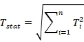
If five mating components each carry a tolerance of ±0.08 mm, the worst-case stack-up reaches ±0.40 mm. This variance can cause interference fits on sliding shafts or leave wide gaps on sealed enclosures.
Error 3: Specifying Geometries That Violate Tooling Physics
· Zero-Radius Internal Corners: End mills are cylindrical. A sharp internal 90-degree vertical wall requires an infinitely small tool radius. Specifying R=0 requires secondary Electrical Discharge Machining (EDM), increasing cost. Designers should specify internal corner radii at least 15% larger than standard end mill radii (e.g., R=3.5 mm for a 6 mm end mill) to allow continuous tool path motion without dwelling.
· High Aspect-Ratio Deep Pockets: Machining a wall or pocket deeper than 8 times the tool diameter causes tool deflection:
Where deflection (δ) increases exponentially with tool length (L). Tool deflection causes wall chatter, taper errors, and tool breakage.

Real-World Failure Modes in Rapid Aluminum Prototyping
1: Thin-Wall Warping and Post-Unclamping Distortion
Technical Case Study: Aerospace Sensor Housing
· Material: Al6061-T6 plate stock (50 mm starting thickness).
· Part Geometry: 220 mm × 140 mm rectangular enclosure with 1.2 mm wall thickness and a 1.5 mm floor thickness.
· Defect: Upon releasing the part from the vacuum fixture, the floor bowed upward by 0.38 mm, exceeding the flat seal tolerance of 0.05 mm.
Root Cause Analysis
1. Residual Stress Distribution: Extruded and rolled aluminum plates contain internal stress fields (σres) generated during rapid quenching in the T6 heat treatment process.
2. Asymmetric Material Removal: Asymmetric material removal releases internal stresses unevenly, causing the component to bow toward the side with higher residual tension.
3. Over-Clamping Force: Applying high hydraulic or mechanical clamping forces during finishing operations elastically deforms thin-walled features. When released, the material springs back to its unconstrained state.
Dazao Engineering Mitigation Protocol
· Multi-Pass Stress Relief Workflow:
1. Rough machine all faces to leave 1.5 mm of stock material.
2. Perform thermal stress relief annealing: heat to 180°C for 3 hours, followed by slow furnace cooling.
3. Semi-finish machine to leave 0.3 mm of stock material.
4. Unclamp completely to relieve internal stress.
5. Re-clamp lightly using custom soft jaws or vacuum fixtures for the final finish pass.
· Symmetrical Stock Removal: Machine equal material depths from both sides of the stock plate to maintain internal stress equilibrium.
Pain Point 2: Discrepancies Between 2D Engineering Drawings and 3D CAD Models
The Industry Conflict
A common source of rework in cnc prototype machining occurs when the 3D STEP/IGES model conflicts with the 2D PDF drawing.
· Typical Scenario: An engineer updates a hole diameter from 8.00 mm to 8.50 mm in the 2D drawing detailing sheet, but omits updating the underlying 3D solid model.
· The Manufacturer's Dilemma: CAM programmers generate toolpaths directly from 3D CAD models. If they select a tool based on 3D geometry, the finished part will fail the 2D PDF drawing inspection.
Legal Precedent and Standard Operating Protocol
Industry standards state that 2D PDF drawings take legal precedence over 3D model geometry unless explicitly specified otherwise in the purchase order contract.
Dazao Automated Pre-Production Verification
To prevent drawing conflicts, Dazao implements an automated DFM validation process before launching CAM programming:
This protocol identifies parameter mismatches before toolpaths are generated, preventing component scrap.
Pain Point 3: Quotation Creep, Hidden Costs, and Production Drift
Price Creep
Initial low-cost estimates for a rapid aluminum prototype can balloon due to unquoted secondary operations:
Transparency in quoting requires a full line-item breakdown of machining time, setup fees, surface finishing, and quality assurance inspections.
Quality Drift in Low-Volume Runs
A common challenge when transitioning from single prototypes to low volume aluminum production (50 to 1,000 units) is dimensional drift across the batch.
· Causes of Batch Drift:
1. Cutting Tool Wear: Edge recession on carbide tools increases cutting forces and dimensional drift over long runs.
2. Thermal Drift of CNC Machine Kinematics: As the spindle runs continuously, thermal buildup expands the Z-axis ball screws, causing feature depths to creep over time.
3. Fixture Wear: Locating pins on soft jaws wear down over multiple clamping cycles, causing datum shift.
Advanced Metrology & Process Nuances in Custom Aluminum Prototyping
Ambient Temperature Variance and Micro-Inch Tolerance Disputes
The Thermal Expansion Equation
Dimensional inspection discrepancies frequently arise when parts are measured in non-standardized environments. Aluminum has a high Linear Coefficient of Thermal Expansion (CTE):
ΔL=L0⋅α⋅ΔT
Where:
· L0 = Nominal dimension (mm)
· α = Coefficient of Thermal Expansion for Al6061 (23.6×10⁻⁶ K−1)
· ΔT = Temperature differential relative to the standard reference temperature (Tref=20∘C/68∘F)
Real-World Measurement Dispute
A shop floor operates without climate control at an ambient temperature of 32°C in summer. A 500 mm long machined aluminum prototype structural frame is machined and verified using calipers on the production floor.
ΔL=500 mm⋅(23.6×10−6 K−1)⋅(32∘C−20∘C)=0.1416 mm (141.6 μm)
The machinist measures the part at 32°C as 500.00 mm. Upon delivery, the customer inspects the component inside a climate-controlled CMM room at 20°C. The measured length drops to 499.86 mm. If the drawing calls for a tolerance of 500.00 ± 0.05 mm, the part is rejected as undersized.
Dazao Thermal Stabilization Standard
1. Thermal Soaking Protocol: All prototype aluminum parts arriving from the machine shop floor must remain inside the CMM metrology laboratory for a minimum of 4 hours prior to final inspection to achieve thermal equilibrium at 20°C ± 0.5°C.
2. On-Machine Temperature Probing: High-precision 5-axis CNC machines at Dazao integrate thermal sensors on ball screws and spindles, dynamically offsetting axis coordinates based on real-time workpiece temperature readings.
Surface Coating Pre-Compensation Traps and Bearing Fit Failures
Anodizing is an electrochemical conversion process that converts surface aluminum into aluminum oxide (Al2O3). Anodizing grows both inward into the substrate and outward from the original surface.
Anodizing Dimensional Rules
· Type II Sulfuric Anodizing: Typical film thickness ranges from 10 µm to 20 µm. The dimensional buildup per surface equals 50% of total thickness (5 µm to 10 µm). This increases the external diameter of a pin by 10 µm to 20 µm and decreases the internal diameter of a hole by 10 µm to 20 µm.
· Type III Hardcoat Anodizing: Typical film thickness ranges from 25 µm to 50 µm. The dimensional buildup per surface reaches 12.5 µm to 25 µm, shifting external diameters up by 25 µm to 50 µm.
Pitch Diameter Shift in Internal Threads
Anodizing internal M6×1.0 threads without pre-compensation often causes bolt binding. The effective pitch diameter (d2) of a 60-degree internal thread decreases according to:

Where tbuild is the outward growth per surface. A 10 µm surface growth reduces the internal pitch diameter clearance by 40 µm, causing standard M6 bolts to bind during assembly.
Dazao Pre-Compensation CAM Workflow
To maintain post-coating tolerances for an ISO H7 press-fit bearing journal (e.g., Ø28.000 +0.021/-0.000 mm) subjected to Type III Hardcoat Anodizing (50 µm thickness):
1. Calculate Surface Growth: (0.025 mm).
2. Adjust CAM Machining Target: Machine the internal bore oversized by 0.050 mm on diameter. Target pre-anodize bore size = Ø28.050 mm.
3. Execute Electrochemical Processing: Hardcoat anodizing deposits 0.025 mm per surface, contracting the final ID back to the required Ø28.000 mm.

Tool Wear and Fixture Drift in Prototype-to-Low-Volume Transition
Transitioning from a single cnc aluminum prototype to a run of 500 units introduces progressive tool wear and fixture deflection.
The Physics of Tool Edge Recession
As carbide end mills cut aluminum, abrasive silicon inclusions cause flank wear (VB). Tool edge rounding increases radial cutting forces (Fr), inducing tool deflection:
Fr ∝ VB0.65
As Fr increases, the tool flexes away from the workpiece, causing bore diameters to shrink and boss features to expand across consecutive parts.
Dazao Production Stability Controls
· Automatic In-Process Tool Setting: Laser tool setters measure tool radius (r) and length (L) inside the machine every 25 operations, applying real-time dynamic offsets to CAM register memory.
· Hardened Steel Fixture Inserts: Soft jaws are upgraded to hardened D2 steel locating pins (60 HRC) for orders exceeding 50 units, eliminating datum wear during repetitive clamping.
Aluminum Alloy Selection Matrix for Engineering Prototypes
Selecting the proper alloy balances mechanical strength, corrosion resistance, surface finishing compatibility, and unit cost.
Detailed Alloy Profiles
Al6061-T6: Universal Standard
Al6061-T6 contains silicon and magnesium as its primary alloying elements. It provides balanced machinability, weldability, and resistance to environmental stress corrosion cracking. It accepts Type II and Type III anodizing readily, making it the default material choice for functional prototypes.
Al7075-T6: High-Strength Aerospace Grade
Alloyed with zinc (5.1–6.1%) and magnesium (2.1–2.9%), Al7075-T6 yields tensile strength up to 572 MPa, matching many structural steels while maintaining one-third the mass density. It is used in aerospace structural brackets, high-stress robotic arms, and racing suspension arms. However, its high copper content reduces corrosion resistance, requiring protective anodizing.
Al2024-T3: High Fatigue Resistance
Containing copper (3.8–4.9%) as the primary additive, Al2024-T3 exhibits high fracture toughness and cyclic fatigue resistance. It is used in aircraft wing skins and tension-loaded structural members. Machinability is high, but weldability is poor, and it requires protective coatings to prevent galvanic corrosion.
Al5052-H32: Non-Heat-Treatable Sheet Metal & Enclosures
Magnesium (2.2–2.8%) serves as the primary solid-solution strengthener in Al5052. It cannot be heat-treated to higher tempers, but offers high workability for combined CNC machining and sheet metal bending operations, alongside high resistance to marine corrosion.
Technical Material Comparison Matrix
|
Alloy Designation |
Tensile Yield Strength (MPa) |
Hardness (Brinell / HB) |
Machinability Rating (%) |
Corrosion Resistance |
Anodizing Quality |
Raw Material Cost Factor |
Ideal Application |
|
Al6061-T6 |
276 |
95 |
90% |
Excellent |
Excellent |
1.0x |
Structural housings, brackets, heat sinks |
|
Al7075-T6 |
503 |
150 |
70% |
Moderate |
Good |
2.1x |
Aerospace spars, high-stress robotics |
|
Al2024-T3 |
345 |
120 |
75% |
Poor |
Fair |
1.8x |
High-fatigue flight components |
|
Al5052-H32 |
193 |
60 |
55% |
Superior |
Good |
1.1x |
Marine enclosures, bent bracketry |
|
Al7050-T7451 |
469 |
140 |
65% |
Good |
Fair |
2.6x |
Thick aerospace bulkheads |
DFM Optimization Rules & Prototype Cost Reduction Breakdown
The Five Structural Elements of Prototype Cost
For a deeper dive into pricing factors, refer to our complete aluminum CNC machining cost breakdown.
1. Machine Hours / Spindle Time (50%): Machine hourly rate multiplied by cycle time. Deep pockets, high surface finish requirements, and complex 5-axis toolpaths increase total cycle time.
2. Raw Material Stock (15%): Billet size required to enclose the part envelope. High scrap rates (removing >85% of starting billet mass) drive up material costs.
3. Fixturing & Machine Setups (15%): Non-recurring engineering (NRE) costs for programming CAM toolpaths, setting work coordinate systems (WCS), and machining custom soft jaws.
4. Surface Finishing (10%): Secondary processing fees for bead blasting, Type II/III anodizing, laser marking, and precision masking.
5. Quality Assurance & CMM Metrology (10%): First Article Inspection (FAI) reports, GD&T verification, and material test report (MTR) documentation.
Six DFM Rules to Reduce Prototype Costs
Applying our practical aluminum CNC machining design guide during the CAD modeling stage ensures maximum precision at minimal expense.
Rule 1: Radius Optimization (R≥0.35×Depth)
Avoid sharp floor-to-wall transitions. Internal vertical corner radii should equal at least one-third of the cavity depth. This permits the use of larger, stiffer end mills, running at higher chip loads without tool chatter.
Rule 2: Minimum Wall Thickness Standard
Maintain minimum wall thicknesses of at least 0.8 mm for supported internal ribs and 1.5 mm for unsupported outer walls. Thinner walls require slow step-over finishing passes to control deflection, increasing cycle time.
Rule 3: Cap Thread Depth at 2× Nominal Diameter
Tapping deeper than twice the nominal thread diameter (2D) provides negligible structural thread engagement strength improvement, while exponentially increasing the risk of tap breakage inside deep holes.
Maximum Thread Depth=2.0⋅Dnominal
Rule 4: Consolidate Setup Orientations
Design geometry so features can be machined from 3 or fewer orientations. Each additional setup step requires physical manual intervention, WCS recalibration, and specialized soft-jaw creation.
Rule 5: Limit Cavity Aspect Ratios (Depth-to-Width ≤4:1)
Pockets deeper than 4 times their width force the machinist to use long-reach necked tooling. Reduced tool rigidity requires lighter cutting passes to manage tool deflection, increasing machining time.
Rule 6: Standardize Hole Specifications
Align hole sizes with standard drill bit diameters (e.g., 3.0 mm, 4.2 mm, 5.0 mm, 6.8 mm, 8.5 mm). Custom hole sizes require non-standard reamers or specialized helical interpolation milling passes.
Dazao Cost-Reduction Case Study
Drone Camera Gimbal Arm Optimization
· Initial Customer Design: Machined from a solid Al7075-T6 block. Features included zero-radius internal pockets, 0.5 mm thin side walls, deep 12:1 aspect ratio cutouts, and custom thread depths (3.5D).
· Original Unit Cost (10 Prototypes): $485.00 / Part.
· Dazao DFM Optimization Actions:
1. Converted alloy selection from Al7075-T6 to Al6061-T6 (Sufficient calculated yield safety factor of 2.8).
2. Increased wall thickness from 0.5 mm to 1.2 mm.
3. Modified internal corner radii from R=0.5 mm to R=3.0 mm.
4. Capped thread depth at 1.8D.
5. Consolidated side-hole features to reduce setup orientations from 5 to 2.
· Final Unit Cost: $281.30 / Part (42% unit cost reduction without compromising structural strength or camera mounting interfaces).
Post-Processing & Surface Finish Impact on Mechanical Tolerances
Post-machining processes alter the dimensional profile and surface roughness of an aluminum prototype.
Bead Blasting Mechanics
Bead blasting projects glass sphere media (100–170 mesh) at controlled air pressure (0.3–0.5 MPa) to remove tool marks and produce a uniform matte surface.
· Dimensional Impact: Removes 2 µm to 5 µm of substrate metal from exposed outer surfaces.
· Roughness Shift: Smooths high tool ridges (Ra3.2 μm→Ra1.6 μm), but over-blasting critical seal surfaces can degrade planarity.
Anodizing Options
When evaluating anodizing surface finishing options, engineers must account for protective film growth and surface hardness across three primary industry classifications:
· Type I Anodizing (Chromic Acid): Yields a thin coating (1 µm to 3 µm). Used on fatigue-sensitive aerospace components due to negligible reduction in fatigue life.
· Type II Anodizing (Sulfuric Acid): Layer thickness of 10 µm to 20 µm. Provides moderate wear resistance and accepts color dyes (Black, Red, Blue, Clear).
· Type III Hardcoat Anodizing: Layer thickness of 25 µm to 50 µm. Increases surface microhardness to 400–600 HV (50–55 HRC), delivering wear resistance comparable to hardened tool steel.
Precision Masking Techniques
When specific zones (such as grounding pads, bearing fits, or sliding journals) must remain raw aluminum or maintain tight tolerances, specialized masking is applied prior to anodizing:
· Silicone Plugs & Pull-Plugs: Seal blind and through-threaded holes from anodizing fluids.
· Precision Die-Cut Vinyl Tape: Masks flat mating faces and electrical grounding contacts.
· Liquid Masking Resins: Applied via automated dispensers over complex curved journal surfaces, cured via UV light, and peeled away post-anodizing.
Surface Finishing Matrix
|
Finishing Process |
Typical Layer Thickness Shift |
Surface Roughness Change (RaRa) |
Surface Hardness |
Electrical Conductivity |
Primary Function |
|
As-Machined (Standard) |
0.000 mm |
1.6 − 3.2 μm |
Base Alloy (95 HB) |
Fully Conductive |
Raw functional fit testing |
|
Fine Pass Milling |
0.000 mm |
0.4 − 0.8 μm |
Base Alloy (95 HB) |
Fully Conductive |
O-ring seals, bearing seats |
|
Bead Blasting (Glass) |
-0.003 mm |
1.2 − 1.8 μm |
Base Alloy |
Fully Conductive |
Removing directional tool marks |
|
Type II Anodize |
+0.005 to +0.010 mm |
+0.2 µm shift |
200 – 300 HV |
Non-Conductive (Insulator) |
Cosmetic coloring, light wear |
|
Type III Hardcoat |
+0.012 to +0.025 mm |
+0.5 µm shift |
400 – 600 HV |
Non-Conductive (Insulator) |
Extreme wear, hydraulic bores |
|
Chem Film (Chromate) |
< +0.001 mm |
No Change |
Base Alloy |
Conductive |
Corrosion protection with EMI grounding |
Scaling Strategy: From Prototype to Low-Volume Production
Moving from a single prototype to low volume aluminum production (50 to 1,000 components) requires transitioning from manual setups to repeatable manufacturing processes.
Fixturing Evolution: Single-Part to Multi-Station Tombstones
· Prototype Fixturing: Uses standard machine vises and soft jaws. Machining is performed one part at a time, resulting in higher labor costs per unit.
· Low-Volume Production Fixturing: Uses multi-station tombstone fixtures mounted on 4-axis or 5-axis horizontal machining centers (HMC). Multiple billets are loaded onto a single fixture, reducing tool change overhead and maximizing machine uptime.
Quality Control Protocols
Maintaining dimensional repeatability across production runs requires rigorous CMM inspection and quality control protocols.
First Article Inspection (FAI)
Before running a production batch, a complete First Article Inspection (FAI) report is generated in accordance with AS9102 guidelines. Every drawing dimension, GD&T callout, and material certification is measured, verified, and documented.
Statistical Process Control (SPC)
During production runs, critical characteristics (CC) and key control characteristics (KCC) are tracked using control charts (Cp and Cpk indices).

Maintain a target Cpk≥1.33 to ensure process variability remains well within specified drawing limits.
Buyer Decision Matrix & Supplier Evaluation Framework
Evaluating a potential aluminum prototype supplier requires verifying their equipment infrastructure, quality systems, and engineering capabilities.
Checklist for Assessing Supplier Capabilities
1. Machine Equipment Profile: Does the facility operate 4-axis and 5-axis CNC milling centers equipped with high-speed spindles and active thermal compensation?
2. In-House Metrology Equipment: Is the factory equipped with a dedicated, climate-controlled inspection lab housing a Coordinate Measuring Machine (CMM) with calibrated scanning probes?
3. Quality Certifications: Does the manufacturer hold third-party certified ISO9001:2015 or IATF16949:2016 quality management credentials?
4. DFM Engineering Review: Does the supplier provide a formal DFM technical review detailing tool access limitations, radius adjustments, and pre-coating compensation before starting production?
Five Required Documentation Inputs for RFQ Submission
To receive an accurate and timely quote for a cnc aluminum prototype, provide the following five inputs:
1. 3D CAD Model: Native STEP (.step) or IGES (.iges) file.
2. 2D Engineering Drawing: PDF format containing explicit GD&T callouts, critical fit tolerances, datum targets, and thread specifications.
3. Material Specification: Exact alloy grade and temper designation (e.g., Al6061-T6, Al7075-T6).
4. Surface Finishing Callout: Detailed coating specifications (e.g., MIL-A-8625 Type III Hardcoat, Class 1 Clear, 50 µm thickness) with explicit masking zones defined.
5. Order Volume & Target Schedule: Quantity required for initial prototype validation alongside forecasted low-volume production requirements.
Why Select Xiamen Dazao Machinery as Your Prototyping Partner?
Founded in 2000, Xiamen Dazao Machinery operates a specialized manufacturing facility equipped with multi-axis CNC machines and automated metrology equipment. Our engineering team conducts pre-production DFM reviews on every CAD model, evaluating tolerance stack-ups, tool access, and coating build-up to prevent quality issues before cutting metal. Whether you require a single functional aluminum prototype or a low-volume production run, Dazao delivers components built to exact engineering specifications.
Conclusion & Actionable Next Steps
High-precision aluminum prototype machining requires balancing material selection, GD&T callouts, thermal stability, surface finish growth, and manufacturing process controls. Over-specifying tolerances without accounting for manufacturing physics inflates production costs and extends lead times. By applying sound DFM principles, establishing unified datum structures, and accounting for post-processing dimensional shifts, product teams can optimize unit costs while maintaining functional reliability.
Next Engineering Steps
Review your CAD models and 2D engineering drawings against the DFM principles outlined in this guide.
Check thread specifications and bearing journal tolerances to ensure surface finish growth has been compensated for.
Submit your files to our engineering team for a comprehensive DFM review and line-item quotation.

FAQs
01.Why did my thin-walled aluminum prototype bow after unclamping from the vise?
02.How do I prevent anodizing from ruining my tight bearing hole tolerances?
03.Why is my machine shop rejecting my 2D PDF drawing when the 3D STEP file looks correct?
04.Why did CMM inspection fail when shop floor calipers showed exact nominal dimensions?
05.What is the most cost-effective aluminum alloy for functional prototype testing?
06.How do I avoid unexpected hidden fees on my custom aluminum prototype quotes?





