


Selecting between cast vs billet aluminum is an architectural manufacturing decision governed by production volume, geometric complexity, internal stress thresholds, and dynamic load profiles. While billet aluminum vs cast aluminum parts exhibit distinct metallurgical properties: wrought billet or cast aluminum for CNC parts offers void-free grain flow and superior tensile fatigue strength (R=−1), whereas near-net cast vs billet aluminum for production cuts material removal rates by up to 75% at scale.
However, sourcing decisions often break down over shop-floor variables: billet internal stress relief causing thin-wall potato-chipping, datum drift during secondary billet vs cast aluminum machining, and subsurface micro-porosity exposed during final thread milling. Adhering to proven industrial aluminum CNC machining practices ensures consistent quality. Below is the operational evaluation framework used by Dazao Machinery across precision robotics, automotive powertrain, and semiconductor equipment programs.
Microstructure & Forming: Cast Aluminum vs Billet Aluminum Dynamics
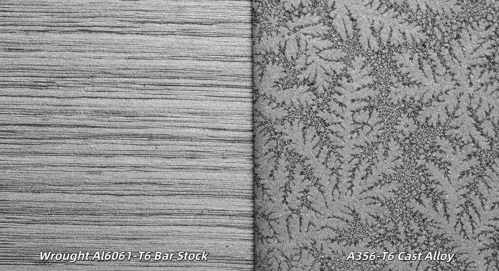
The technical evaluation of cast aluminum vs billet aluminum begins at the phase change boundary. Wrought aluminum stock (billet, plate, and extruded bar) undergoes severe plastic deformation during continuous casting, hot rolling, or extrusion. This mechanical processing breaks up cast dendritic structures, closes gas voids, and aligns secondary phase particles along the primary working axis.
Cast aluminum alloys (such as A356, A380, and ADC12) solidify directly from the molten phase within a mold cavity. The microstructure is dictated by local cooling rates, solidification gradients, and nucleation dynamics. This creates distinct physical and operational constraints when machining billet vs cast aluminum components.
Grain Flow vs Dendritic Voids: Why Billet Aluminum Parts Resist Micro-Cracks
· Wrought Billet (Al6061-T6, Al7075-T6): Extruded or rolled billet features a continuous, directional grain flow. The material density reaches 100% of theoretical limits (2.70 g/cm3 for 6061). The absence of gas entrainment and solidification shrinkage guarantees uniform pressure boundaries, making billet aluminum parts the primary choice for vacuum chambers, hydraulic manifolds, and ultra-high-vacuum (UHV) semiconductor applications.
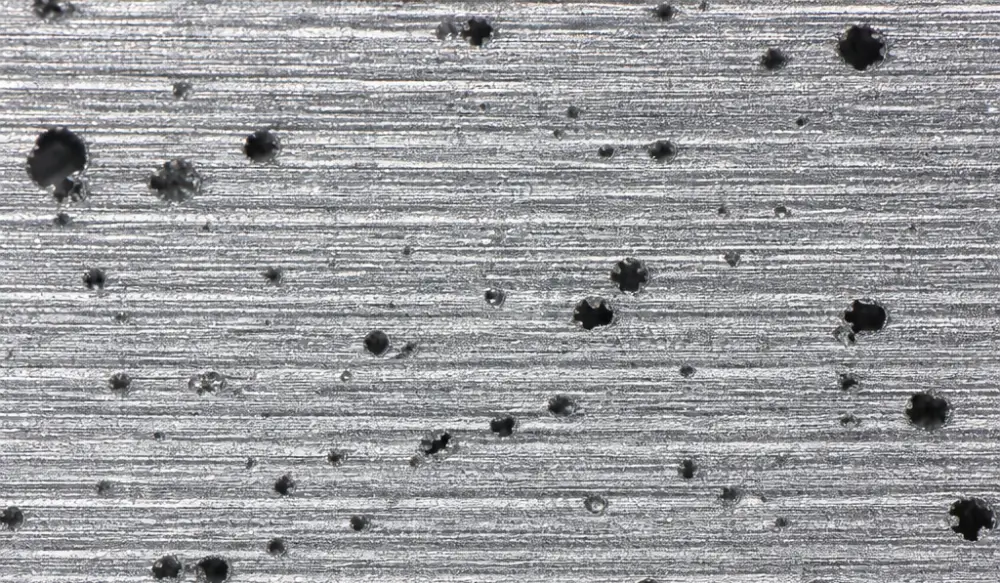
· Cast Formations (A356-T6, A380, ADC12): Gravity die casting, sand casting, and high-pressure die casting (HPDC) establish an equiaxed dendritic crystal network. Solidification shrinkage occurs at the intersection of thick and thin cross-sections. Hydrogen solubility drops drastically from liquid (0.7 cm3/100g) to solid (0.04 cm3/100g), leaving micro-porosity at grain boundaries. Even with degassing and vacuum-assisted casting, micro-shrinkage remains a statistical variable governed by ASTM E155 reference radiographs.
Subtractive CNC Milling vs Net-Shape Tooling Constraints
The geometric pathway governs part economics. Machining billet vs cast components represents a battle between tool reach accessibility and draft physics:
1. Subtractive CNC Milling (Billet): Utilizing integrated precision CNC machining services with 5-axis toolpaths allows undercut clearance, zero draft angles (0∘), internal intersecting fluid channels, and deep, thin-walled rib matrices. The limitation is raw tool accessibility, spindle clearance, and cutter aspect ratio (L/D>5 induces deflection and chatter).
2. Near-Net Cast Geometry: Casting delivers complex curved surfaces, internal tortuous passages via sacrificial sand cores, and mass-optimized bulk shapes without material waste. However, tooling requires draft angles of 1.0∘ to 3.0∘, minimum uniform wall thicknesses (≥2.5 mm for sand/gravity, ≥1.2 mm for HPDC), and generous internal fillets (R≥1.5 m) to prevent hot tearing during solidification.
Surface Integrity & Anodizing: The Silicon Content Trap in Cast Alloys
Surface conversion behavior is an essential divider when evaluating when to use billet aluminum vs cast aluminum:
· Billet (6061/7075): Low silicon content (Si≤0.8%) enables precision aluminum surface finishing and anodizing capabilities under MIL-A-8625 (Type II decorative and Type III hardcoat),yielding uniform optical finishes with dielectric breakdown voltages exceeding 1000V. Surface roughness can reach Ra 0.4 μm (16 μin) directly off the machine spindle.
· Cast Alloys (A356, A380, ADC12): Castings contain high silicon fractions (7.5% to 12.0% Si) to lower melt viscosity and reduce hot cracking during casting. During acid pickling and anodizing, insoluble elemental silicon particles precipitate on the surface, causing an uneven, dark gray, blotchy patina. High-pressure die castings frequently blister during the 60∘C to 90∘C seal bath due to the expansion of trapped sub-surface air pockets.
Table 1: Microstructure, Chemistry, and Machining Parameters Comparison
|
Engineering Parameter |
Wrought Al6061-T6 (Billet) |
Wrought Al7075-T6 (Billet) |
Cast A356-T6 (Permanent Mold) |
Cast ADC12 (High-Pressure Die) |
|
Primary Forming Method |
Direct Extrusion / Hot Rolling |
Hot Rolling / Forging |
Gravity Permanent Mold |
High-Pressure Die Casting |
|
Nominal Composition |
Al-1.0Mg-0.6Si-0.28Cu |
Al-5.6Zn-2.5Mg-1.6Cu |
Al-7.0Si-0.35Mg-0.2Fe |
Al-11.0Si-2.5Cu-0.3Mg-1.0Fe |
|
Material Density (g/cm3) |
2.70 |
2.81 |
2.68 |
2.74 |
|
Internal Void / Porosity Risk |
0.0% (NDT Class 1 Solid) |
0.0% (NDT Class 1 Solid) |
ASTM E155 Level 1-2 |
ASTM E155 Level 3-4 |
|
Typical As-Machined Ra |
0.4 μm (16 μin) |
0.2 μm (8 μin) |
0.8 μm (32 μin) |
1.6 μm (63 μin) |
|
Type III Hard Anodize Response |
Consistent Hardness (60-65 HRC equivalent) |
High Hardness (Dark Bronze shade) |
Poor (Discolored gray/yellow) |
Unacceptable (Severe spot blistering) |
|
Material Removal Rate Efficiency |
High (Vc=800 m/min) |
High (Vc=600 m/min) |
Moderate (Vc=400 m/min) |
Abrasive on tooling (Vc=350 m/min) |
Billet vs Cast Aluminum Machining: 3 Costly Shop-Floor Traps
Published engineering handbooks rarely document the scrap drivers encountered on production floors. In real-world manufacturing across hundreds of programs, sourcing failures between cast and billet aluminum trace back to three specific physical phenomena.

Internal Stress Relief: Billet Hogging & Thin-Wall Warpage
A common error among design engineers is assuming that specifying solid Al6061-T6 guarantees dimensional stability because there are no casting defects. More granular machining details can be referenced in our dedicated billet aluminum machining guide.
1. The Mechanism: Standard T6 temper plate stock retains a self-equilibrating internal residual stress profile: compression on the outer skin (≈−40 to −60 MPa), balanced by tension in the center core (≈+30 to +50 MPa).
2. The Failure: When machining deep pockets or asymmetric thin-wall structures (such as UAV avionics bays or robot chassis trays), the removal of the top compression layer destroys this equilibrium. The tensile stress in the remaining core pulls the base upward, causing long-plate components to warp into a curved shape (often deviating by 0.50 mm to 1.80 mm over a 300 mm span).
3. The Dazao Floor Countermeasure:
· Switch procurement to Al6061-T651 or Al7075-T7451 plate, which undergo a 1.5% to 3.0% controlled mechanical stretch after solution heat treatment to mechanically relieve up to 85% of internal stresses.
· Implement a two-stage roughing-finishing protocol: rough machine all pockets leaving 0.8 mm stock, unclamp the vice to allow free springback, re-clamp under low torque (≤15 N⋅m), and execute the final finishing passes.
Datum Drift & Core Shift in Secondary Cast CNC Operations
Engineers evaluating secondary cast machining operations frequently experience positional scrap when machining cast blanks using pure billet coordinate logic. Adhering to standardized cast aluminum CNC machining protocols is mandatory to stabilize production.
1. The Mechanism: Sand casting and permanent mold castings are subject to parting line step variation (±0.4 mm to ±0.8 mm per ISO 8062-3 DGT), draft taper variability, and core thermal float during metal pour.
2. The Failure: Clamping a cast blank onto raw cast surfaces using standard three-jaw chucks or flat vice jaws creates an unrepeatable machining datum (G54). When boring bearing journals or milling sealing faces, the cutter paths align with machine axes rather than the cast wall mass, resulting in uneven wall thicknesses (e.g., 1.2 mm on one side, 2.8 mm on the opposite side), thin walls, broken tapped holes, or broken through-holes.
3. The Dazao Floor Countermeasure:
· Never locate off parting lines. Integrate three raised, non-functional tooling pads (10 mm×10 mm) directly into the cast tool design to serve as dedicated 3-2-1 primary datums.
· Deploy on-machine Renishaw touch-trigger probing routines to perform best-fit feature calculations across multiple cast reference points before triggering critical finish cuts.
Subsurface Porosity: The Late-Stage Scrap Multiplier in Cast Machining
The most expensive scrap occurs when a casting is rejected at the final machining step.
1. The Mechanism: Castings solidify from the mold surface inward. The outer surface skin (1.0 mm to 1.5 mm) cools rapidly, forming a dense, void-free chill layer. The center of thick bosses solidifies last, trapping dissolved gases and shrinkage micro-voids.
2. The Failure: An engineer designs an O-ring groove or an M10x1.0 pressure-port thread requiring a 3.0 mm deep plunge. The CNC tool cuts straight through the dense skin and exposes the porous core. The part subsequently fails pressure decay leak testing (≥1.0×10⁻⁴ mbar⋅L/s), rendering all upstream CNC machine time, thread milling, and tool life a total write-off.
3. The Dazao Floor Countermeasure:
· For fluid-sealing surfaces, enforce a maximum machining stock allowance of 1.0 mm on the casting drawing to avoid breaking through the chilled layer.
· Mandate vacuum impregnation (per MIL-I-17563C Class 1/3 with anaerobic thermosetting polymer) as a standard operational step after rough CNC machining but before final diamond finish milling.
Billet vs Cast Aluminum Strength: Static Yield vs Dynamic Fatigue
When specifying billet vs cast aluminum strength, nominal datasheet values provide an incomplete picture. Real-world components face cyclic multi-axial fatigue, impact loads, and thermal fluctuations.
High-Cycle Fatigue (HCF) Knockdowns & Notch Sensitivity (Kt)
· Static Strength: Al6061-T6 billet yields at 276 MPa with an ultimate tensile strength (UTS) of 310 MPa. Premium aerospace-grade Al7075-T6 achieves a yield of 503 MPa and UTS of 572 MPa. In contrast, cast A356-T6 yields at 165 to 185 MPa with a UTS of 230 to 260 MPa.
· High-Cycle Dynamic Fatigue: Under cyclic tension-compression loading (R=−1, 107 cycles), cast alloys exhibit high fatigue knockdowns. The micro-voids and brittle silicon needle plates act as internal stress risers (Kt≥3.0), initiating micro-cracks at stress levels down to 50 to 60 MPa. Wrought 6061-T6 maintains a fatigue endurance limit of 95 to 100 MPa, while 7075-T6 sustains 160 MPa.
Anisotropic Plate Weakness (Z-Axis) vs Isotropic Cast Integrity
· Billet Anisotropy (The Z-Axis Vulnerability): Heavy rolled plate possesses directional mechanical properties. While longitudinal (L-axis) and transverse (LT-axis) properties match standard spec sheets, short-transverse (ST / Z-axis, through-thickness) elongation drops from 12% to as low as 2.5% to 4.0%, with fracture toughness (KIC) dropping by up to 35%. Applying high tensile loads across the plate thickness can trigger delamination or premature brittle shear.
· Casting Isotropy: Solidification without directional rolling results in quasi-isotropic mechanical properties. A structural mounting bracket cast in A356-T6 delivers uniform yield strength and elongation across the X, Y, and Z axes, simplifying FEA stress simulations under multi-directional loading.
Generative Design Tradeoffs: Internal Cavities vs Draft Angle Mass
· Modern generative design creates organic, skeletal load paths. Machining a continuous, closed, hollow boxed cross-section from a solid billet requires split-part designs, alignment dowels, and O-ring/welded joints.
· Casting (specifically semi-permanent mold or investment casting with soluble ceramic/sand cores) can produce monolithic, hollow enclosed chambers. However, open cast webbing requires 1.5∘ to 2.0∘ draft angles, which thickens deep-pocket ribs and can add 8% to 15% back to the net component mass compared to a thin-wall billet structure with zero-draft vertical ribs.
Table 2: Mechanical Performance Under Static & Dynamic Load Regimes
|
Mechanical Property |
Al6061-T6 Billet |
Al7075-T6 Billet |
Cast A356-T6 (Sand) |
Cast A356-T6 (Permanent Mold) |
Cast ADC12 (HPDC) |
|
Yield Strength, Rp0.2(MPa) |
276 |
503 |
165 |
185 |
160 |
|
Ultimate Tensile Strength,Rm(MPa) |
310 |
572 |
230 |
260 |
310 |
|
Elongation at Break, A(%) |
12.0% |
11.0% |
3.5% |
5.0% |
1.5% - 2.0% |
|
Fatigue Strength (107cycles,R=−1,MPa) |
96 |
160 |
55 |
65 |
42 |
|
Fracture Toughness, KIC(MPa⋅m1/2) |
29.0 |
25.0 (L-Dir) / 18.0 (ST-Dir) |
16.0 |
18.5 |
12.0 |
|
Brinell Hardness (HBW) |
95 |
150 |
70 |
80 |
85 |
|
Directional Uniformity |
Anisotropic (Z-axis knockdowns) |
Anisotropic (High ST notch sensitivity) |
Quasi-Isotropic |
Quasi-Isotropic |
Quasi-Isotropic (Dense skin only) |
Billet vs Cast Aluminum Cost: Volume Breakeven & TCO Breakdown
Procurement evaluations of billet vs cast aluminum cost frequently fail because teams calculate material mass multiplied by ingot spot price while ignoring operational yield losses. Total Cost of Ownership (TCO) in precision components is governed by tooling amortization, chip generation ratios, machine spindle time, and post-machining validation overhead. Calculating your setup against established aluminum CNC machining cost drivers provides transparent baseline forecasting.
TCO Formula: Material Removal Rate (MRR) vs Tooling Amortization
The complete unit manufacturing cost (Cunit) is modeled through the following equation:

Where:
· Ctooling = Hard tool steel die tooling or permanent mold pattern cost ($0 for billet; $4,500 to $45,000+ for casting dies).
· N = Total amortized production batch volume.
· Mraw and Mscrap = Initial blank mass and generated aluminum swarf mass. A hogged billet part with an 85% Material Removal Rate (MRR) buys 10 kg of raw plate at $4.80/kg to yield a 1.5 kg finished part, recovering only $1.40/kg on loose wet chips.
· TCNC⋅Rspindle = Machine time multiplied by machine hourly burden rate ($45/hr for 3-axis; $85 to $130/hr for multi-pallet 5-axis CNC).
· Cpost = Secondary thermal treatment, vacuum resin impregnation, vibratory deburring, and CMM surface verification.
· αscrap = Statistical defect and rejection scrap rate multiplier (typically 0.5% to 1.5% for billet; 4.0% to 9.0% for raw castings).

Cast Aluminum vs Billet Aluminum for Low Volume to Mass Scale
Tier 1: 1 to 50 Units (Rapid Prototyping & Low-Volume Specialization)
· Manufacturing Path: 100% subtractive CNC milling from solid extruded bar or rolled plate (Al6061-T651 / Al7075-T6) utilizing high-speed multi-axis CNC milling.
· Cost Drivers: Zero upfront tooling expenditure ($C_{\text{tooling}} = $0). Lead time is 3 to 7 working days. Specifying cast aluminum vs billet aluminum for low volume at this stage introduces mold lead times of 5 to 8 weeks and non-amortized NRE penalties that increase per-unit costs by 300% to 800%.
Tier 2: 50 to 500 Units (The Mid-Volume Gray Zone)
· Manufacturing Path: Optimized multi-axis high-speed billet machining versus rapid tooling and low-volume prototyping solutions (such as 3D-printed sand molds or semi-permanent master tooling).
· Cost Drivers: This is the most contested threshold in production planning. If the design requires over 65% material removal, sand casting with basic CNC cleanup breaks even around 120 to 180 units. If high-speed roughing tools can achieve metal removal rates over 600 cm3/min with simple 2-axis vices, billet remains financially superior up to 350 units.
Tier 3: 500 to 5,000+ Units (Series Production Scaling)
· Manufacturing Path: Deploying high-pressure aluminum die casting services or gravity permanent mold casting paired with dedicated multi-spindle CNC transfer line finishing.
· Cost Drivers: Raw material savings and reduced spindle cycle time dominate unit economics. A casting cycle takes 45 to 90 seconds per shot, reducing CNC cycle time from 55 minutes down to 4.5 minutes of precision datum and seal face cutting. Tooling costs ($12,000 to $35,000) fully amortize to under $5.00 per unit.
Design Freeze & ECO Risks: CAM Re-programming vs Tooling Re-sink
A critical variable in tooling decisions is drawing stability:
· CAM Program Modification (Billet): Modifying a mounting hole pattern, bearing bore depth, or boss thickness on a billet part requires only 1 to 2 hours of CAM reprogramming and updated G-code simulation. Part modifications incur zero scrap tooling costs.
· Die Modification (Casting): In high-pressure die casting, moving a rib or adding material requires electrical discharge machining (EDM) or structural CNC welding on H13 hardened tool steel inserts (52 HRC). If an engineering change removes material from a core shutoff or changes a primary wall thickness, the entire die cavity must be remade, halting production for 4 to 6 weeks.
Table 3: Economic Breakeven Simulation (Robotic Arm Actuator Housing, Mass: 1.85 kg Finished)
|
Production Variable |
Low Batch (15 Units) - Billet CNC |
Mid Batch (200 Units) - Billet CNC |
Mid Batch (200 Units) - Cast A356 + CNC |
High Batch (3,000 Units) - HPDC + CNC |
|
Initial Tooling / Die Cost ($) |
$0 |
$0 |
$6,500 (Gravity Hard Mold) |
$24,000 (Multi-Cavity HPDC Tool) |
|
Raw Material Cost per Part ($) |
$72.00 (12.5 kg 6061-T6 block) |
$62.00 (Bulk purchase discount) |
$14.50 (2.3 kg near-net cast blank) |
$8.20 (2.1 kg ADC12 cast shot) |
|
Raw Material Scrap Recovery ($) |
-$12.50 (10.65 kg chips) |
-$11.20 (10.65 kg chips) |
-$0.55 (0.45 kg chips) |
-$0.30 (0.25 kg chips) |
|
CNC Machining Spindle Time |
58 minutes @ $85/hr |
46 minutes (Optimized paths) |
11 minutes (Finish datums only) |
3.5 minutes (Dedicated fixture) |
|
CNC Machining Cost per Part ($) |
$82.16 |
$65.16 |
$15.58 |
$4.95 |
|
Post-Processing / Impregnation / QA |
$15.00 (Type II Anodize) |
$12.00 (Type II Anodize) |
$18.50 (Impregnation + E-coat) |
$7.80 (Chemical conversion + QA) |
|
Amortized Tooling Cost per Unit ($) |
$0.00 |
$0.00 |
$32.50 |
$8.00 |
|
Total Realized Unit Cost ($) |
$156.66 |
$127.96 |
$80.53 |
$28.65 |
|
Production Readiness Lead Time |
4 Business Days |
8 Business Days |
6 Weeks (Tooling + T1 Sample) |
10 Weeks (PPAP Validation) |
Cast vs Billet Aluminum for Production: The Hybrid Manufacturing Route
The most efficient production method for complex metal components is a hybrid strategy: casting near-net profiles to establish structural envelopes, cooling channels, and bulk mass, followed by high-precision 5-axis CNC machining for geometric tolerances, sealing boundaries, and kinematic mounts.
Geometric Decoupling: As-Cast Envelopes vs Critical CNC Features
Implementing rigorous aluminum CNC machining design guidelines enables smooth feature partitioning across tooling transitions:
· Retained As-Cast Envelope: Outer aerodynamic geometries, mass-relief windows, structural rib grids, non-sealing heat dissipation fins, and internal fluid cooling passages. These regions are produced to ISO 8062-3 (CT5 to CT7) tolerances, requiring no spindle cutting time.
· Precision CNC Machined Zones: Bearing journals retaining strict aluminum CNC machining tolerances (IT6/IT7 bore fits), dynamic O-ring glands (Ra 0.8 μm max with zero cutter lay chatter), dowel pin locating holes (±0.008 mm center-to-center true position), and high-pressure planar manifold surfaces (Flatness 0.015 mm).
Closed-Loop Machining: Floating Fixtures & In-Process CMM Probing
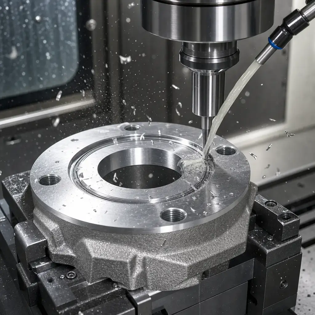
To eliminate datum drift and core-shift scrap, Dazao Machinery executes a closed-loop machining protocol for cast blanks:
1. Hydraulic Compensation Fixturing: Cast preforms are supported on spherical leveling rests and clamped using multi-point sequencing hydraulic actuators. This prevents casting clamping deflection during heavy face milling.
2. On-Machine Probing via Macro Algorithms: On-Machine Probing via Macro Algorithms: Deployed across advanced 5-axis CNC machining centers, spindle-mounted Renishaw OMP60 probes measure six casting datum points before running cutter paths. The CNC controller calculates a mathematical best-fit transformation matrix. If core shift has skewed the physical part by +0.4 mm along the X-axis, the tool coordinate system offsets by +0.4 mm, ensuring uniform wall thicknesses and eliminating off-center machining scrap.
When to Use Billet Aluminum vs Cast Aluminum: 7-Point Sourcing Matrix
Use this quantitative framework to evaluate manufacturing routes across new engineering designs:
Table 4: 7-Point Quantitative Sourcing Decision Matrix
|
Evaluation Dimension |
Specify Billet Aluminum (100% CNC Machined) |
Specify Near-Net Cast Preform + CNC Machined |
Sourcing Impact Factor |
|
1. Annual Volume (N) |
N≤200 units/year |
N≥500 units/year |
Tooling ROI & unit breakeven |
|
2. Target Part Geometry |
Flat plates, deep prismatic pockets, deep thin walls with zero draft |
Curved shells, complex fluid loops, integrated hollow structures |
Tooling feasibility & machine reach |
|
3. Dimensional Precision |
True position ≤0.010 mm, flatness ≤0.015 mm everywhere |
Mixed: Raw cast profile ±0.5 mm, localized critical bores ±0.010 mm |
Spindle utilization time |
|
4. Surface Finishing |
Uniform Type II/III decorative or hard anodizing (Optically clear) |
Powder coating, chemical conversion, wet paint, non-decorative anodize |
Silicon content aesthetic limits |
|
5. Pressure & Fluid Sealing |
Ultra-high vacuum (<10−8 Torr),hydraulic pressure ≥20 MPa |
Ambient drain housing, cooling jackets, low-pressure gas (≤0.6 MPa) |
Subsurface void leak risks |
|
6. Dynamic Stress Level |
High cyclic fatigue, dynamic impact (R=−1, cyclic shear load) |
Low-to-moderate static compressive load, steady structural support |
Micro-crack initiation limits |
|
7. Production Lead Time |
Rapid turn: 3 to 10 days direct from 3D CAD/CAM |
Standard lead time: 6 to 12 weeks for tooling build and FAI |
Time-to-market speed |
Dazao Senior Engineering Sourcing Recommendations
1. Execute a Phased Sourcing Strategy: Machine initial prototype iterations (Alpha to Gamma stages) from wrought Al6061-T651 billet. This validates field performance and allows geometry updates without tooling scrap. Transition to permanent mold or high-pressure die casting tooling once drawings have completed one full production run without revision.
2. Pre-Compensate Tooling for Draft Angles: When preparing for casting conversion, ensure your engineering team does not simply pass the solid billet CAD model to the moldmaker. Add draft angles of 1.0∘ to 2.0∘ to internal pockets, add minimum radii of R≥2.0 mm to sharp corners to lower stress concentration factors (Kt), and set nominal wall thicknesses to a uniform 3.0 mm±0.5 mm.
3. Audit Machine Datums Early: Mandate that your manufacturing partner incorporates raw datum target nests into the casting CAD model. Machining cast blanks without predefined 3-2-1 tooling points leads to dimensional scrap on coordinate measuring machines.

FAQs
01.How does billet aluminum strength compare to cast aluminum?
02.When should you use billet aluminum over cast aluminum?
03.Why is cast aluminum cheaper than billet aluminum in high volume?
04.Can you anodize cast aluminum parts to match billet finish quality?
05.What causes billet aluminum to warp during CNC machining?
06.How do manufacturers prevent leak paths on machined cast sealing faces?





