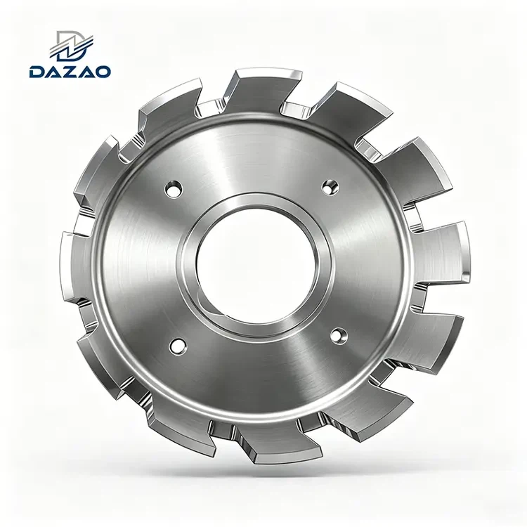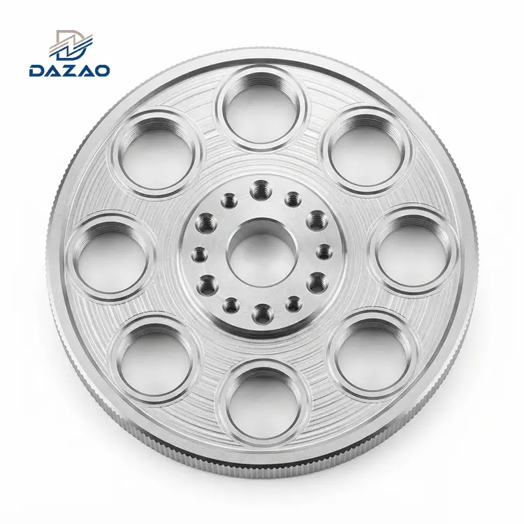
Precision Machined Aluminum Optical Filter Wheels Supplier
Sub-arcsecond indexing accuracy and optical-grade alignment for advanced imaging systems.
Core Technical Specs & Procurement Highlights:
±15 arcsec indexing for precision machined cnc filter wheel.
Motorized aluminum optical filter wheel with G1 balancing.
SM1 threaded optical filter wheel with thread compensation.
Cage system compatible filter wheel with ≤0.02mm runout.
Ultra thin optical filter wheel for astronomy down to 2mm.
Custom aluminum filter wheel OEM manufacturer with 7-day FAI.

Engineering Overview and CNC Machining Capabilities
A robust structural foundation engineered for stability, light-tight performance, and zero optical alignment drift.
Xiamen Dazao Machinery produces monolithic precision machined aluminum optical filter wheels manufactured via 4-axis and 5-axis CNC milling services from 6061-T6 and 7075-T6 aerospace aluminum alloys. Designed for integration into optical setups, these components support manual and motorized configurations with 6 to 24 filter positions.
Our manufacturing setup natively accommodates standard optical thread interfaces including SM1 (1.035"-40 UNS), C-mount (1"-32 UN), and 30mm/60mm optical cage system mountings. By controlling angular cumulative error to ≤±15 arcseconds and maintaining flat surfaces within 0.01 mm, these components prevent optical axis drift and vignetting across microscopy, spectroscopy, and astronomical instrumentation.

Field Failure Analysis and Engineering Corrective Protocols
Real-world machining challenges solved through closed-loop positioning and stress-relief processing.
Case 1 High Speed Microscopy Indexing Deviation
· Problem: An 8-position high-speed motorized filter wheel supplied to a biological microscopy manufacturer met aperture diameter tolerances but exhibited a cumulative angular indexing error approaching 2 arcminutes. During automated filter switching, this error caused optical axis deviation, generating asymmetrical vignetting and edge blur during high-magnification imaging.
· Root Cause Analysis: Machining filter apertures without closed-loop angular positioning verification allowed tool deflection and thermal drift to accumulate across circular pitch divisions.
· Engineering Corrective Action: Implemented closed-loop rotary axis indexing control using direct-drive rotary tables on 5-axis CNC mills. Every initial unit undergoes 3D CMM angular inspection to limit cumulative pitch error within ≤±15 arcseconds. High-speed variants are dynamic-balanced to ISO 1940 G1 standard and subjected to thermal stress relief. Sub-pixel alignment consistency is maintained with switching repeatability under ≤0.005 mm.
Case 2 Optical Thread Binding and Cage System Misalignment
· Problem: A batch of SM1-threaded filter wheels produced for research optical assemblies exhibited a 40% failure rate during client installation. Standard SM1 lens tubes bound inside the threaded ports, while cage rod mounting holes showed a 0.1 mm runout relative to the optical axis.
· Root Cause Analysis: Standard mechanical thread profiles were machined without calculating the dimensional buildup of black anodize coatings (12–15 µm film thickness per surface). Additionally, thread axes were machined in a separate setup from the cage mounting reference datum.
· Engineering Corrective Action: Formulated a thread offset compensation database tailored to specific precision aluminum anodizing options (Type II black vs. Type III hardcoat). Threads are cut oversized prior to surface treatment and validated post-anodizing using standard SM1 Go/No-Go optical plug gauges. Bore coaxiality and cage system mounting holes are now machined in a single clamping setup, guaranteeing coaxiality within ≤0.02 mm.
Case 3 Stress Induced Warping on Ultra Thin Astronomical Plates
· Problem: A 2.0 mm thick ultra-thin filter wheel for deep-sky astronomical cameras demonstrated 0.01 mm flatness at factory inspection but warped to 0.08 mm flatness within 10 days of assembly. The resulting filter tilt caused optical coma and field distortion.
· Root Cause Analysis: Single-sided high-speed milling imparted asymmetric residual stresses within the thin aluminum plate. Ambient temperature fluctuations triggered stress relaxation, warping the structure.
· Engineering Corrective Action: Adopted a symmetric step-milling strategy, removing material in alternating passes not exceeding 0.3 mm per depth of cut. Introduced a dual thermal aging process: cryogenic stress relief at -196°C followed by artificial thermal aging prior to final finish passes. Every thin-profile production lot is held in storage for 7 days before final flatness verification; drift must remain ≤0.005 mm to pass final QA.

Optical Structural Precision and Manufacturing Differentiators
Proprietary machining protocols engineered to eliminate cross-threading, vibration, and post-coating distortion.
Closed Loop Indexing Accuracy Verification
Unlike general machine shops relying on nominal indexing tolerances, every optical filter wheel undergoes angular verification.
· Inspection Protocol: Direct angular measurement using a high-accuracy rotary stage paired with CMM contact probing at every filter pocket center.
· Target Metric: Cumulative angular pitch error ≤±15 arcseconds; switching position repeatability ≤0.005 mm across 1,000 continuous test cycles.
· Result: Eliminates optical axis misalignment during multi-channel imaging.
Pre Compensated Optical Thread Clearance
Optical threads require tight tolerances to prevent cross-threading and binding while ensuring light-tight seals.
· Pre-Machining Offset: Standard pitch diameters are offset to accommodate specific anodize layer growth rates (MIL-A-8625 Type II/III).
· Datum Alignment: Thread pitch centerlines are tied directly to the central bore axis (≤0.02 mm coaxiality) in a single setup.
· Physical Fit Inspection: 100% of thread ports are verified using physical optical mating components before shipment.
Dynamic Balance and Thermal Stress Relief Protocols
Specialized application demands require tailored physical stability controls:
· High-Speed Variants: Dynamic balance corrected to ISO 1940 G1 grade to eliminate high-RPM vibration in automated fluorescence microscopy setups.
· Ultra-Thin Variants (<2.5 mm): Balanced material removal and dual-stage thermal stress relief guarantee flatness stability ≤0.01 mm over long-term operations.

Technical Specifications and Machining Parameters
Verified dimensional, mechanical, and surface parameters tailored for high-precision optical setups.
|
Parameter / Feature |
Technical Specification |
|
Material Options |
Aluminum 6061-T6, 7075-T6, 2024-T3 |
|
Aperture Configurations |
6, 8, 10, 12, 18, 24 positions (Custom configurations available) |
|
Indexing Angular Accuracy |
≤±15 arcseconds cumulative angle error |
|
Positioning Repeatability |
≤0.005 mm linear equivalent |
|
Surface Flatness |
≤0.01 mm across entire diameter (Ultra-thin series verified after 7-day dwell) |
|
Dynamic Balance Class |
ISO 1940 G1 grade (for high-speed motorized series) |
|
Interface Compatibility |
SM1 (1.035"-40 UNS), C-Mount (1"-32 UN), 30mm / 60mm Cage Systems |
|
Machining Envelope |
Diameter 25.4 mm (1 inch) up to 152.4 mm (6 inches) |
|
Thickness Limits |
Minimum 1.5 mm up to 25.0 mm |
|
Surface Finish / Anodize |
MIL-A-8625 Type II Black Matte Anodize, Type III Hardcoat, Chem Film |
|
General Machining Tolerance |
±0.005 mm on critical diameters and bores |
|
Prototyping Lead Time |
7 working days (Includes First Article Inspection report) |

Precision CNC Milling Compared to Plastic Molding and Die Casting
Why monolithic billet aluminum milling outperforms molded plastics and die castings in demanding optics.
|
Metric / Requirement |
CNC Billet Aluminum |
Injection Molded Plastic |
Die-Cast Aluminum |
|
Indexing Accuracy |
High (≤±15 arcsec) |
Low (≥2 arcmin, moisture expansion) |
Moderate (≥45 arcsec, draft angle variance) |
|
Structural Rigidity |
Superior (E = 69–72 GPa) |
Poor (Flexing under high acceleration) |
Moderate (Porosity risks, lower yield) |
|
Thread Precision (SM1/C) |
Direct CNC cut + Gaging |
Molded (Prone to flash/stripping) |
Post-tapped (Porosity damages threads) |
|
Tooling & NRE Cost |
Zero Tooling Cost |
High (5,000–25,000 mold cost) |
High (8,000–30,000 die cost) |
|
Prototyping Speed |
Fast (7 Days) |
Slow (6–10 weeks for mold) |
Slow (8–12 weeks for tooling) |
|
Low-Volume Feasibility |
Ideal (1–500 units) |
Uneconomical |
Uneconomical |
Eliminating hard tooling makes 5-axis CNC machining an ideal choice for custom aluminum prototyping and small-to-medium production batches, ensuring direct design flexibility without upfront mold amortization.

Engineering Selection Guide for Optical Equipment Integration
Match your optical system requirements with the ideal drive mechanism, interface, and alloy.
Drive System Selection Parameters
· Manual Filter Wheels: Intended for laboratory test setups and educational equipment. Simple mechanical detent stops provided.
· Motorized Filter Wheels: Intended for automated imaging and spectroscopy. Features direct encoder interfaces, low inertia cutouts, and alignment dowel locations.
Optical Interface Compatibility Standards
· SM1 Thread (1.035"-40 UNS): Standard for 1-inch optics integration; pre-compensated for matte black anodizing.
· C-Mount (1"-32 UN): Direct integration with scientific industrial camera sensors and microscope ports.
· Cage System Compatibility: Precision-bored 6.0mm rod holes with tight spacing tolerances (±0.01mm) for direct incorporation into 30mm or 60mm optical cage setups.
Industry Specific Configuration Guidelines
· Fluorescence Microscopy: Specify 7075-T6 material with G1 dynamic balancing to limit vibration during high-RPM switching.
· Space-Constrained Astronomy Cameras: Specify the ultra-thin series (<2.5 mm) with dual-stage stress relief to maximize clear aperture within strict envelope limits.

Modular Customization Options and Surface Treatments
Versatile design adaptabilities from custom pocket counts to low-reflectivity optical surface treatments.
· Custom Position Counts: Custom pocket layouts supporting up to 24 positions or mixed-diameter optical filters (e.g., combined 12.7mm and 25.4mm ports).
· Motor Housing Integration: Direct-machined motor mount plates, precision gearbox alignment bores, and optical home-position sensor slots.
· Optical Surface Finishes: Low-reflectivity matte black anodize (absorptance >95% in visible spectrum), conductive chromate conversion coating, laser-engraved position indices.

Quality Assurance Workflow and Engineering Quote Request
A transparent end-to-end production pipeline backed by CMM inspection and full material traceability.
Step by Step Production Workflow
1. Engineering DFM Review: Analysis of STEP/IGS files for machining clearance, thread offsets, and stress distribution.
2. CAD/CAM Programming: Generating 4-axis / 5-axis toolpaths targeting single-setup datum references.
3. Material Verification: Spectrographic raw material check and mill test report (MTR) logging.
4. Precision Machining: CNC milling, thread cutting with pre-anodize offsets, and deburring under 20x magnification.
5. Thermal Processing: Cryogenic and thermal aging stress relief for ultra-thin or high-speed specifications.
6. Surface Finishing: Matte black optical anodizing, hardcoat anodizing, or chem-film treatment.
7. Final Optical Assembly & Inspection: CMM dimensional inspection, angular indexing verification, and optical component thread mating checks.
Multi Stage Quality Assurance Protocols
· Incoming Raw Material Control: We provide fully traceable batch material certificates for 6061-T6 and 7075-T6 billet aluminum machining with every production lot.
· First Article Inspection (FAI): Complete 3D CMM inspection report provided with every sample order prior to volume production approval.
· Optical Fit-Check Audit: Physical threading verification using standard SM1, C-mount, or cage components on 100% of finished parts.
· Packaging Protection: Custom-cut polyethylene foam interiors with sealed anti-static vacuum wrapping to prevent physical or surface damage during international transport.
Production Lead Times and Global Logistics
· Minimum Order Quantity (MOQ): 1 unit for prototype testing; volume pricing tiers available for batch runs.
· Lead Times: 7 business days for prototypes; 10 to 15 business days for standard production orders.
· Trade Terms Supported: EXW, FOB, CIF, DDP (Door-to-Door Duty Paid).
· IP Protection: Standard Non-Disclosure Agreements (NDAs) executed prior to drawing review.
· Shipping Documentation: Commercial Invoice, Packing List, Certificate of Conformance (CoC), Material Test Reports (MTR), CMM Inspection Sheets included.
Application Industries & Engineering Use Cases
Sub-pixel alignment, thermal stability, and low-outgassing structural solutions for precision optical systems.

Fluorescence & Biological Microscopy
Multi-channel fluorescence setups requiring sub-100ms filter switching and ISO 1940 G1 dynamic balancing for vibration-free sub-pixel alignment.

Spectroscopy & Environmental Sensing
Spectrophotometers and optical gas analyzers utilizing SM1/C-mount interfaces with ≤±15 arcsecond indexing accuracy to eliminate light leakage.

Astronomical Instrumentation & Imaging
Telescope camera filter assemblies utilizing ultra-thin (<2.5 mm) stress-relieved profiles to prevent sub-zero thermal warping.

Industrial Machine Vision & Inspection
High-speed inline sorting and wafer inspection equipment built from 6061-T6/7075-T6 aluminum delivering ≤0.005 mm position repeatability.
FAQs

01.How do you prevent high-speed vibration and image blur in motorized optical filter wheels?
02.How do you ensure SM1 and C-mount threads do not bind or stick after black anodizing?
03.What machining techniques prevent warping on thin optical filter wheels during long-term use?
04.How do you minimize internal light reflection on machined aluminum filter wheels?
05.What indexing angular accuracy and position repeatability can your CNC process guarantee?
06.Can custom optical filter wheels be integrated directly into 30mm or 60mm cage systems?
Ready to start your custom optical filter wheel project?
Submit your 2D and 3D CAD files (STEP, IGS, X_T, or PDF) to our engineering team today.
We will review your drawing dimensions, thread requirements, and tolerances, providing a comprehensive DFM evaluation and quote within 24 hours.
Contact Us

Hot Tags: aluminum optical filter wheel,precision machined cnc filter wheel,sm1 threaded optical filter wheel,motorized filter wheel