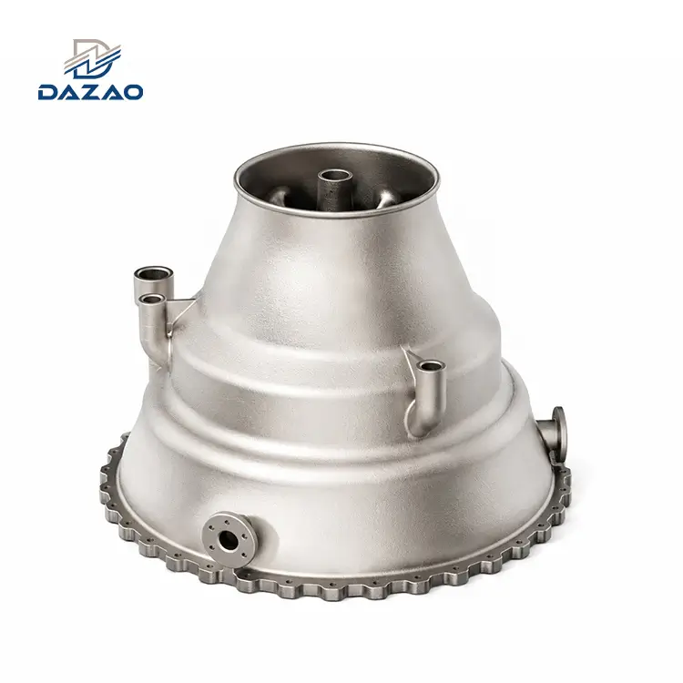
SLM 3D Printed Aerospace Fuel Nozzle For Turbofan Propulsion
High-Yield Propulsion Fluid Control Components Certified to Extreme Aerospace Tolerances
Core Engineering Features:
Single-piece component consolidates 20+ brazed parts.
Inconel 718 & CoCrMo options lower dry weight by 25%.
HIP post-processing boosts high-cycle fatigue life by 5x.
3-stage powder removal reduces residual particles <0.01%.
Industrial CT scan detects subsurface voids and microcracks.
Internal fluid channels polished below Ra 1.0 μm.
1-piece prototype MOQ; batches delivered in 15 days.

Advanced SLM Additive Manufacturing For Aerospace Fuel Injectors
Monolithic additive configurations engineered to withstand high-pressure combustion forces.
This industrial-grade, aerospace fuel nozzle is manufactured using an advanced metal 3D printing service using Selective Laser Melting (SLM) technology. The process consolidates complex multi-piece fuel swirlers, metering orifices, and cooling pathways into a single-piece component. Utilizing proprietary parameter profiles for Inconel 718 and CoCrMo superalloys, the resulting component eliminates brazed and welded joints that are historically prone to thermal fatigue. These nozzles are engineered to operate continuously in environments with gas temperatures up to 650°C and injection pressures exceeding 5.0 MPa.
Engineering Datasheet And Physical Performance Specifications
Verifiable metallurgical profiles, physical thresholds, and dimensional tolerances.
|
Technical Parameter |
Specification Value / Limit |
|
Manufacturing Process |
Selective Laser Melting (SLM) / Laser Powder Bed Fusion (LPBF) |
|
Standard Material Options |
Inconel 718 (AMS 5666 / UNS N07718), CoCrMo Alloy (ASTM F75) |
|
Envelope Dimension Capacity |
Up to 600 mm × 600 mm × 600 mm |
|
Material Density |
≥ 99.9% (Measured via Archimedes Method) |
|
Internal Channel Tolerances |
±0.05 mm (As-printed); down to ±0.02 mm with post-milling on 5-axis CNC machining centers |
|
Surface Finish (Internal Channels) |
Ra 1.0 to 1.6 μm (Post abrasive flow machining) |
|
Surface Finish (Outer Surfaces) |
Ra 0.8 μm (After multi-axis CNC turn-milling) |
|
Internal Powder Cleanliness |
Residual un-melted powder < 0.01% by total volume |
|
High-Cycle Fatigue Endurance |
Exceeds 5,200 test stand hours (at 600°C cyclic loading) |
|
Quality Certifications |
ISO 9001:2015, full material traceability, industrial CT scan reports |
|
Minimum Order Quantity (MOQ) |
1 Piece (Prototype validation stage) |
Root-Cause Technical Case Studies From Previous Aerospace Engine Projects
Practical solutions derived from real-world propulsion engineering setbacks.
Our processes are built upon real manufacturing feedback. Rather than presenting clean corporate profiles, we document the technical resolutions of early-stage production failures to assure your engineering team of our rigorous methodology.
Resolution Of Swirling Micro-Channel Flow Obstruction
In 2021, we developed a fuel swirl validation nozzle featuring 14 internal, intersecting helical cooling passages with a target flow variance of ≤3.0%. Standard mechanical vibration and dry pressurized-air purging left micro-fine powder agglomerates at the intersection of the helical channels. During hot fire testing, 5 out of 12 test articles exhibited flow rate deviations of up to 18.2%, with partial channel blockages leading to localized hot spots. This delayed the client's project validation by two weeks and cost us $16,500 in air-freight shipping, replacement parts, and delay compensation.
To resolve this, we engineered a dedicated three-stage wet powder evacuation system utilizing an automated ultrasonic chemical bath, followed by abrasive flow machining (AFM) with custom polymer media. This protocol reduced residual un-melted powder levels to <0.01%, stabilizing subsequent flow deviations below 2.0%.
Elimination Of Residual Thermal Stress Distortion In Consolidated Assemblies
In 2022, a single-piece consolidated fuel injector was designed to replace a 12-component brazed assembly on a commercial turbofan derivative. Direct translation from 3D models to print files without simulation resulted in excessive residual thermal stresses during printing. Post-heat-treatment dimensional inspection revealed a flatness deviation of 0.21 mm on the main mounting flange and a coaxiality runout of 0.15 mm at the fuel inlet nozzle, rendering the parts un-mountable. The entire 18-part production run was scrapped, incurring a loss of $25,000.
To resolve this, we integrated finite element analysis (FEA) build-process simulation to model thermal gradients and residual stresses. We redesigned the support structures with conformal heat-sink paths and added a 0.5 mm machining allowance on critical mounting faces. Critically, we implemented a stepped stress-relief annealing process prior to wire EDM plate separation. Final flange flatness is now controlled under 0.05 mm.
High-Cycle Thermal Fatigue Crack Mitigation At Nozzle Discharge Orifices
In 2023, we produced production-grade fuel nozzle tips for a commercial high-altitude UAV jet turbine, requiring an operating lifetime of ≥1,000 thermal cycles. Parts delivered using baseline SLM parameters cracked around the fuel discharge orifices after 420 hours on the engine test stand. Metallurgical evaluation showed that high surface roughness (Ra 6.3 μm) on the internal surfaces had acted as stress concentration points, initiating micro-fractures under high thermal cycling. This failure resulted in a $14,000 warranty claim and redesign cost.
To resolve this, we modified our post-processing routine to include Hot Isostatic Pressing (HIP) to eliminate sub-surface microscopic gas voids, paired with high-pressure abrasive flow polishing to reduce internal surface roughness to Ra 1.0 μm. Testing demonstrated that these changes extended the nozzle tip's life to over 5,200 thermal cycles without structural decay.

Proprietary Stress-Relief, Powder Evacuation, and Polishing Protocols
Systematic methods to eliminate structural micro-porosity and secure fluid pathway purity.
Chemical-Physical Powder Evacuation Process Flow
To address powder accumulation inside complex geometries, we apply a multi-step routine:
· High-Frequency Multi-Axis Mechanical Demolding: Mechanical fluid-dynamic vibration is tuned to the natural frequency of the internal cavities to loosen dry powder.
· Ultrasonic Detergent Immersion: A custom chemical solvent and ultrasonic cavitation loosen semi-sintered boundary particles.
· Abrasive Flow Machining (AFM): A polymer-based viscous abrasive carrier is pumped through the channels under pressure, smoothing internal surfaces to Ra 1.0 μm and removing any remaining powder particles.
Hot Isostatic Pressing For Micro-Porosity Elimination
We optimize your component geometry before production:
· FEA Topology Reduction: Material is removed from zero-stress regions to achieve a 25% weight reduction while maintaining safety margins.
· Hot Isostatic Pressing (HIP): Components are heated to 1,120°C under 100 MPa of inert Argon gas to collapse internal micro-pores and achieve ≥99.9% metallurgical density.
· Solution & Aging Heat Treatment: This process precipitates the strengthening gamma-double-prime (γ′′) phase in Inconel 718, matching or exceeding the fatigue resistance of standard forged variants.
Industrial CT Non-Destructive Testing And Fluid Flow Calibration
Our inspection protocol is non-destructive and data-driven:
· High-Resolution Industrial CT Scanning: We run a complete volumetric scan of each production block to map the entire internal structure, confirming channel wall thickness and identifying any subsurface voids down to 0.05 mm.
· Hydraulic Spray & Spray-Angle Patternation Testing: Every nozzle undergoes flow rate testing under representative operating pressures to ensure that flow and spray characteristics fall within the engineered range.
Structural Performance Comparison: Monolithic SLM vs Conventional Brazed Assemblies
How single-component structural consolidation reduces weight and fatigue susceptibility.
|
Evaluation Criteria |
Conventional Multi-Part Assembly (Brazed) |
Integrated SLM 3D Printed Assembly (Consolidated) |
|
Component Count |
20 to 24 separate pieces |
1 monolithic piece |
|
Joining Technology |
High-temperature vacuum brazing or laser welding |
No joints required (Zero-weld design) |
|
Dry Assembly Weight |
Baseline (100%) |
Reduced by 25% via topology optimization |
|
Internal Channel Design |
Limited to straight drilled lines or simple turns |
Complex, curved, and helical passages |
|
Tooling & Setup Cost |
High (Requires assembly fixtures and braze jigs) |
Zero tooling cost (Direct CAD-to-build) |
|
Typical Prototype Lead Time |
60 to 90 Days (Includes raw stock, machining, brazing) |
7 to 10 Days (Build to post-processing) |
|
Primary Failure Modes |
Joint oxidation, micro-cracking, braze erosion |
None (Monolithic crystalline structure) |
Superalloy Material Metallurgy Matrix: Inconel 718 and Cobalt Chrome
Choosing the right high-temperature superalloy for demanding thermochemical environments.
Inconel 718 (Nickel-Chromium Superalloy)
This material features excellent yield, tensile, and creep-rupture strength at temperatures up to 650°C. It resists oxidation and corrosion over long exposure times. Our facility utilizes specialized Inconel machining and print parameters to optimize these material properties for aerospace propulsion. It is best suited for main combustion chamber fuel nozzles, auxiliary power unit (APU) igniters, and UAV turbojets running standard kerosene/JP-8.
Engineering Caution: Avoid using in environments exposed to highly reducing sulfuric gas mixtures at elevated temperatures, as sulfur can degrade the nickel matrix over time.
CoCrMo Alloy (Cobalt-Chromium-Molybdenum)
This superalloy delivers high hardness, cavitation resistance, and thermal stability up to 800°C. It is best suited for high-sulfur bio-fuels, abrasive fluid metering valves, and operations prone to particulate erosion.
Engineering Caution: CoCrMo has higher material and post-processing tool-wear costs, meaning it should be selected primarily when Inconel's wear limits are exceeded.
Industrial Aerospace Applications And Engine Test Stand Benchmarks
Field-proven performance across commercial aviation, defensive UAVs, and research facilities.
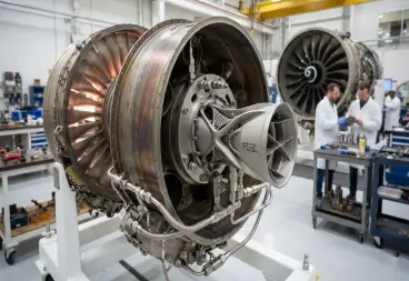
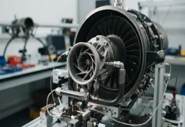
Commercial Turbofan Engines
Drop-in fuel injectors for main combustor stages, providing industry-standard atomization and high-reliability aerospace components.
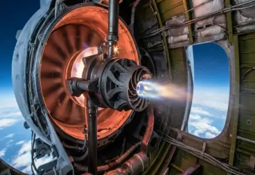
UAV Turbojet Propulsions
Ideal for compact, high-thrust drones where assembly space is limited and every gram of dry weight affects flight range.
Auxiliary Power Units (APUs)
Provides fast ignition and consistent fuel metering under cold-start high-altitude conditions.
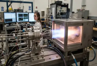
Aerospace Propulsion Research
Allows university and government labs to quickly prototype and test experimental combustion chambers.
Aerospace Part Manufacturing Process and Milestone Timeline
A transparent, ten-step manufacturing sequence from initial simulation to final delivery.
1,Technical Review: Engineering analysis of 3D models (STEP/IGS) and 2D engineering drawings.
2,DFM & Simulation: FEA stress and thermal modeling to optimize support structures and print orientation.
3,Customer Review: Client sign-off on build parameters and post-processing steps.
4,SLM Laser Printing: Monitored build using calibrated Inconel 718 or CoCrMo powder lots.
5,Thermal Stress Relief: In-furnace annealing before removing parts from the build plate.
6,EDM Wire Cut: Precision separation of parts from the build plate.
7,HIP Post-Processing: Hot Isostatic Pressing to close micro-pores and achieve full density [1].
8,Machining & Finishing: Multi-axis CNC milling for interfaces and abrasive flow machining for internal passages.
9,Inspection & Scanning: Dimensions verified by CMM, and internal structures verified by Industrial CT scans.
10,Delivery Shipment: Parts packed with full material traceability and inspection reports.
Aerospace Supplier Quality Systems and Component Traceability Audit Standards
Rigorous verification protocols and non-destructive testing for flight-critical hardware.
· Raw Material Inspection: Every batch of gas-atomized metal powder is tested for particle size distribution and oxygen content (verified below 0.02%). We supply original mill test certificates and do not use recycled powder for aerospace orders.
· In-Process Build Monitoring: Our printers continuously track laser power, oxygen levels (<0.1%), and chamber temperature, keeping log records for audit purposes.
· Post-Process Thermal Certification: Every heat treatment run includes dual thermocouple tracking. The resulting charts are provided to clients to verify the precipitation of mechanical properties.
· Metrology & Traceability Reports: Standard deliveries include full CMM reports, 3D laser scan deviation maps, and industrial CT inspection data.
Additive Manufacturing Aerospace Propulsion Components FAQs

01.Can you manufacture a LEAP engine 3D printed fuel nozzle assembly?
02.What are the main benefits of using an additive manufacturing fuel injector for aerospace?
03.What tolerances can you hold on SLM Inconel 718 fuel nozzle internal channels?
04.Do you have qualified cobalt chrome fuel nozzle 3D printing parameters?
05.How does part consolidation aerospace fuel nozzle 3D print technology reduce risk?
06.Can you perform topology optimization for 3D printed fuel nozzle designs?
Submit your CAD models today for rapid evaluation and commercial pricing within one business day.
Accelerate your development cycle by reducing assembly complexity. Upload your 2D engineering drawings and 3D CAD files (STEP/IGS) to our secure server.
Our engineering team will provide a complete, zero-cost Design for Manufacturability (DFM) review and a formal commercial quotation within 24 business hours.
Contact Us

Hot Tags: 3D printed fuel nozzle, aerospace fuel injector, SLM Inconel 718, cobalt chrome fuel nozzle, additive manufacturing fuel injector