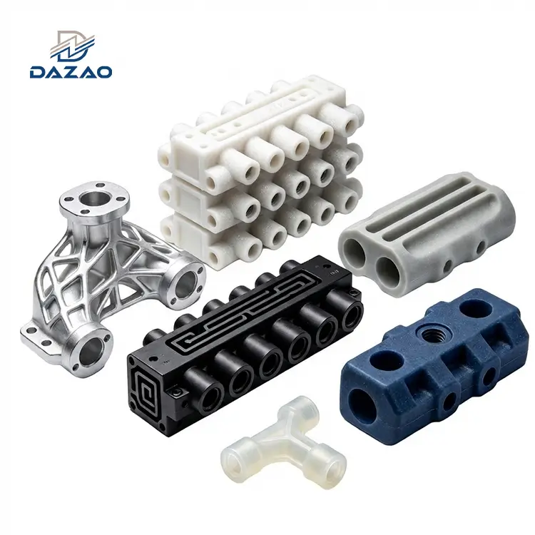
Industrial MJF PA12 3D Printed Pneumatic Manifold Solutions
High-density polymer manifolds engineered to consolidate complex pneumatic circuits and reduce end-of-arm tooling weight.
Core Engineering Features:
Leak-proof 3D printed manifold verified at 1.2 MPa pressure
Lightweight pneumatic manifold reduces EOAT load by 40%.
Topologically optimized pneumatic manifold lowers resistance.
MJF PA12 pneumatic manifold for robust end-use production.
Air-tight 3D printed manifold with ≤0.5% leakage limit.
Custom 3D printed valve manifold shipped in 3 to 7 days.
Integrated pneumatic manifold 3D print saves mounting space.
3D printed pneumatic valve island with 1-piece MOQ.

Technical Overview of 3D Printed Pneumatic Manifold Engineering
Direct consolidation of internal gas flow channels to eliminate assembly joints and potential external leakage paths.
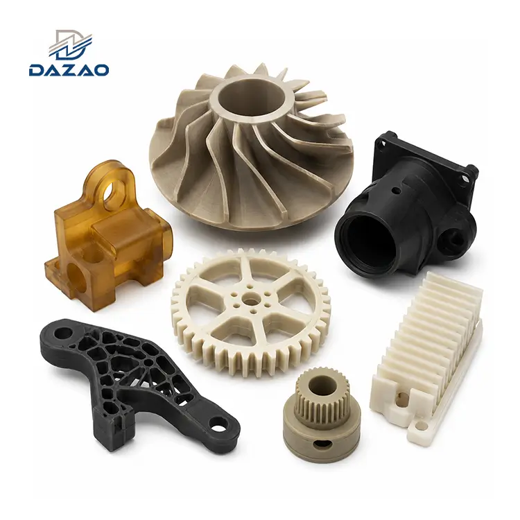
This industrial 3D printed pneumatic manifold replaces heavy, multi-part metal assemblies with a single consolidated component. By utilizing advanced Multi Jet Fusion (MJF) technology, we manufacture the MJF PA12 pneumatic manifold directly with curved internal flow channels to minimize pressure drops. Our production line delivers an integrated pneumatic manifold 3D print that consolidates valves, fittings, and ports, eliminating external leakage paths. Every custom unit undergoes post-processing to ensure a certified air-tight 3D printed manifold suitable for automated lines.

Technical Specifications and Material Grade Boundaries
Precise physical boundaries, tolerances, and operating pressure limits for MJF PA12 and SLA photopolymers.
We maintain strict control over our processing parameters to ensure consistency across different additive manufacturing techniques. Our facility produces parts utilizing both powder-bed fusion and photopolymerization to match the exact chemical and thermal demands of your system. Review our material grades to align our 3D printing capabilities with your specific operating environment. For demanding environments, we utilize high-performance engineering polymers that exhibit excellent mechanical stability under load.
|
Parameter |
MJF PA12 Specification |
SLA (Somos PerForm) Specification |
|
Core Process |
Multi Jet Fusion (MJF) |
Stereolithography (SLA) |
|
Material Grade |
HP 3D High Reusability PA 12 |
DSM Somos PerForm Photopolymer |
|
Max Build Volume |
380 mm × 284 mm × 380 mm |
600 mm × 600 mm × 400 mm |
|
Minimum Wall Thickness |
≥1.5 mm (Recommended) |
≥1.2 mm |
|
Dimensional Tolerance |
±0.15 mm (As-printed) / ±0.02 mm via post-print CNC milling |
±0.10 mm (As-printed) / ±0.02 mm via post-print CNC milling |
|
Operating Pressure |
≤1.0 MPa (Liquid or Gas) |
≤0.5 MPa (Gas Only) |
|
Airtightness Standard |
100% Tested at 1.2 MPa (30 min, Leakage ≤0.5%) |
100% Tested at 0.6 MPa (30 min, Leakage ≤0.5%) |
|
Surface Roughness |
Ra 3.2 to 6.3 μm (As-printed) / Ra 1.6 μm (Bead blasted) |
Ra 0.8 to 1.6 μm (As-printed) |
|
Continuous Temp Limit |
-40°C to 80°C |
-30°C to 120°C (After thermal cure) |
|
Lead Time |
3 Working Days (Prototypes) / 7 Days (Batch) |
3 Working Days (Prototypes) / 7 Days (Batch) |
|
Minimum Order Quantity |
1 Piece |
1 Piece |

Failure Mode and Effects Analysis of Three Field Case Studies
Real-world troubleshooting data and structural corrections that transformed our production quality standards.
We openly share three real-world field failures from our production history and the technical corrective actions we implemented to resolve them.
Root-Cause Analysis: 2022 US Robotic EOAT Micro-Leakage Corrective Action
A US robotics integrator ordered 1,200 end-of-arm tooling (EOAT) manifolds operating under a continuous 0.8 MPa load. We printed the batch using standard MJF settings without post-deposition sealing. Under dynamic vibration, 15% of the manifolds developed micro-porosity leaks, causing vacuum failures and robotic gripper dropouts on the client's SMT line. Total direct loss from air freight and field rework was approximately $20,000 USD.
Corrective Engineering Action: We instituted a mandatory four-stage airtightness protocol. We integrated a vacuum-assisted polymer infiltration process to seal raw PA12 micro-voids. We also mandated a 100% physical pressure-holding test at 1.2 MPa for 30 minutes, keeping the field failure rate under 0.1%.
Root-Cause Analysis: 2021 German Automated Packaging Flow Resistance Correction
An automation client provided CAD files for 800 manifolds that directly replicated a legacy CNC-drilled aluminum block design. Replicating the sharp, 90-degree internal junctions in the 3D printed parts generated turbulent vortices. This restricted flow, causing a 22% delay in actuator response and reducing packaging cycles below target limits. The resulting delay compensations and re-runs cost $15,000 USD.
Corrective Engineering Action: We developed a complimentary fluid simulation pre-check. We now convert all 90-degree intersections into R3–R5 streamlined swept bends while keeping the cross-sectional area uniform. This dropped flow resistance by 32% and restored cylinder actuation speeds.
Root-Cause Analysis: 2023 Australian Integrated Valve Island Assembly Alignment Redesign
An equipment builder consolidated 4-station solenoid valves, fittings, and silencers onto a single manifold. We modeled the threads and ports directly from nominal valve catalog dimensions without allocating tolerances for material shrinkage or thread run-out. This led to a 30% misalignment rate during assembly. Total correction costs reached $11,000 USD.
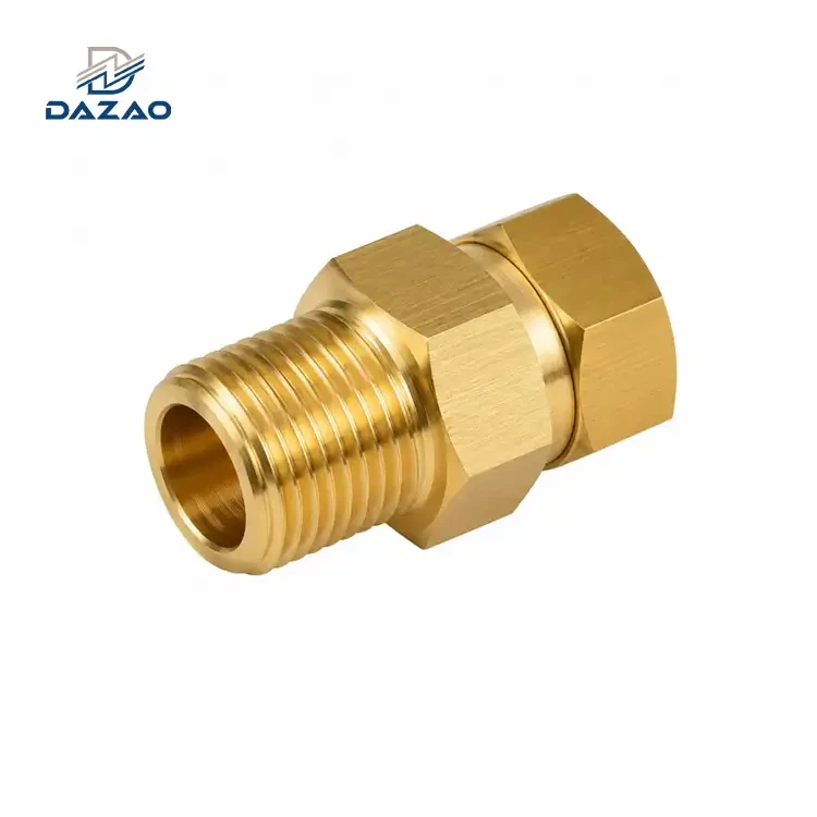
Corrective Engineering Action: We established a standardized physical library of common pneumatic valve interfaces (SMC, Festo, Norgren). We updated thread allowances, pre-tapping depths, and added a First Article physical test-fit sequence before batch production.

Three Standardized Quality and Performance Control Systems
Systematic DFM protocols, pre-print simulations, and thermal crystallization cycles applied to every production batch.
Four-Stage Airtightness Assurance Protocol
Unlike general 3D printing shops that rely on raw sintering, we manage seal integrity at every stage of production:
· Structural Rule: Minimum wall thickness is set at ≥1.5 mm with sweep junctions.
· MJF Sintering: Custom build-chamber thermal profiles maintain high density with a ≥70% virgin powder mix.
· Vacuum Infiltration: Low-viscosity anaerobic polymers fill micro-pores.
· Final Validation: 100% of parts undergo a 1.2 MPa pressure-holding test for 30 minutes with a certified test log.
Pre-Print Fluid Simulation & Topology Optimization
We do not print raw CAD files without a technical DFM analysis. For fluid circuits:
· Flow Optimization: We convert sharp, right-angle internal pathways to curved sweeps, reducing pressure loss by 30%.
· Weight Reduction: We run topology optimization algorithms to strip non-load-bearing mass, reducing manifold weight by up to 40%–60% while maintaining operational mechanical strength. We incorporate these steps into our overall 3D printing capabilities to deliver structurally optimized parts.
Dual-Process Material Selection Matrix & Guardrails
We provide a clear engineering matrix to guide material selection:
· Industrial Production: MJF PA12 pneumatic manifold for structural durability, vibration damping, and impact strength up to 1.0 MPa (not recommended for strong polar solvents or continuous temperatures >80°C).
· Functional Mockup: SLA with Somos PerForm resin for ultra-smooth internals (Ra 0.8 μm) and thermal resistance up to 120°C. Ideal for wind tunnel testing, custom fluid valve mockup units, or industrial impeller 3d printing validation (not recommended for high-impact or frequent assembly/disassembly due to high rigidity and low impact strength).

Standardization and Custom Delivery Workflows
A structured, multi-step validation sequence to ensure zero-defect integration upon receipt.
· Requirement Alignment: Technical analysis of your working fluid, operating pressure, temperature, and mounting envelopes.
· Engineering DFM Review: Fluid simulation and structural path analysis to ensure smooth transitions and wall integrity.
· CAD Approval: Physical 3D models with confirmed thread clearances, tapping depths, and valve mounting footprints.
· Prototyping Run: Rapid 3-day turnaround to produce the first operational manifold.
· Airtightness and Fit-Test: Subjecting the physical prototype to 1.2 MPa pressure holding and actual valve installation.
· Batch Sintering: Utilizing optimized MJF thermal cycles to maintain consistent layer adhesion and mechanical properties.
· Vacuum Imfiltration: Drawing sealing resins deep into the microporous structure under vacuum to seal all channels.
· Final Metrology & Inspection: Coordinate Measuring Machine (CMM) dimensional checks and physical pressure-drop validation.
· Industrial Export Packaging: Customized internal protective inserts and thread caps to prevent transport damage.

Comprehensive Quality Control and Traceability Systems
Standardized verification procedures covering raw materials, build environments, and structural checks.
· Raw Material Inspection: Infrared spectroscopy (FTIR) validation of every incoming powder and resin batch to ensure chemical purity.
· Build Logs: Digital recording of chamber temperature, layer thickness, and laser energy output at 1-second intervals.
· Post-Processing Protocol: Standardized, automated powder removal followed by ultrasonic cleanings to ensure internal channels are clear.
· Physical Pressure Verification: Hydrostatic and pneumatic test benches that record and log leakage rates under load.
· Full Certification Package: Every batch is shipped with material trace reports, dimensional inspection records, and airtightness certificates.

International Logistics and Trade Terms
Flexible transit and billing models tailored to fit global industrial supply chains.
· Trade Terms: We fully support FOB, CIF, and DDP shipping models, handling customs clearance and final transport directly to your dock.
· Packaging Customization: Neutral white-label packaging, client-specific labeling, laser-marked part numbers, and print-on-demand exterior boxes.
· Defect Redeposition Guarantee: In the event of batch assembly faults, we remake and air-freight replacement parts at our own expense.
· Document Packages: Provision of clean customs documentation, RoHS, REACH declarations, and detailed test certificates to simplify compliance.

Industries and Environmental Load Scenarios
Specialized applications requiring chemical resistance, low outgassing, and reduced mechanical payload inertia.
")
End-Of-Arm Tooling (EOAT)
Consolidates vacuum lines and pneumatic feeds on multi-axis robotic arms to reduce mass.

Automated Packaging Lines
Replaces bulky aluminum manifolds on high-cycle cartoning, sorting, and sealing machinery.

Medical Diagnostic Fluidic Modules
Integrates miniature liquid or gas routing pathways within compact diagnostic equipment enclosures.

Automotive Welding & Assembly Cells
Fits tight-envelope valve arrays directly inside welding heads or localized robotic fixtures.
FAQs

01.Can you provide a custom 3D printed valve manifold for specialized machinery?
02.Is it possible to manufacture an integrated pneumatic manifold 3D print with complex internal pathways?
03.What makes a lightweight pneumatic manifold beneficial for robotic applications?
04.Why is an MJF PA12 pneumatic manifold preferred over SLA for end-use industrial applications?
05.How does your factory verify that a leak-proof 3D printed manifold is fully sealed?
06.Can you manufacture a topologically optimized pneumatic manifold to reduce overall material volume?
Direct pathway to submit 2D and 3D CAD files for rapid fluid path assessment and formal price estimation.
Send your 2D and 3D CAD files (STEP, IGS, or Parasolid formats) to our engineering department.
We will perform a DFM check, evaluate fluid optimization options, and deliver an engineering quote within 24 hours.
Contact Us

Hot Tags: 3D printed pneumatic manifold,MJF PA12 pneumatic manifold,integrated pneumatic manifold 3D print,pneumatic circuit manifold 3D print