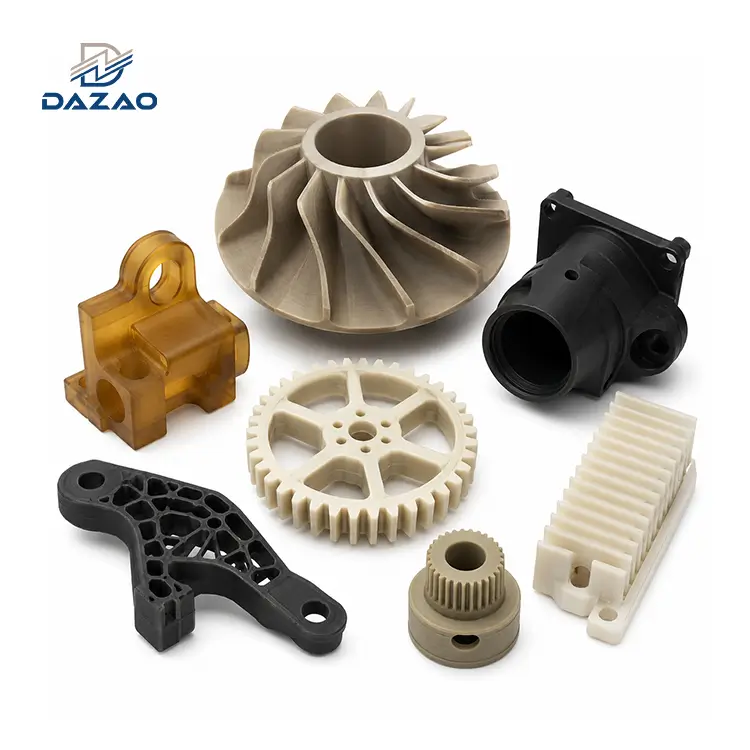
Sourcing aerospace blisks and impellers represents a severe technical hurdle for supply chain managers. High scrap rates and chronic lead time delays are standard outcomes when suppliers lack structural engineering capabilities.
A quick review of engineering forums like reveals the stark reality of impeller production. Comment sections frequently detail the exact same mechanical failures: severe chatter marks on blade edges, tool shank interference deep inside flow channels, and catastrophic end mill breakage when cutting superalloys. The fundamental conflict is obvious. Floor engineers battle aggressive CAM software warnings and excessive spindle vibration, while procurement directors face the financial risk of missed delivery windows.
To solve these supply chain bottlenecks, Xiamen Dazao Machinery leverages its ISO9001:2015 and IATF16949:2016 certified facility in China to implement strict done-in-one manufacturing strategies. By focusing on 5-axis CNC machining impeller workflows, we engineer predictability into high-risk procurement projects.
Overcoming Tolerance Stacking in Complex Aerospace Parts
Traditional 3-axis or 3+2 axis machining centers fail consistently when processing complex aerospace parts. Impellers feature extreme undercuts, overlapping blade geometries, and twisted aerodynamic channels. Using conventional equipment requires operators to physically unclamp, reposition, and re-clamp the billet multiple times to access different angles. Every manual setup introduces microscopic alignment errors. By the third setup, tolerance stacking often exceeds the strict ±0.005mm threshold required for aerospace rotating components, resulting in immediate part rejection.

The core engineering solution lies in continuous spatial freedom. A true 5-axis setup operates on the standard X, Y, and Z linear axes while simultaneously manipulating two rotational axes, A and C. This kinetic synchronization provides total toolpath freedom.
The primary multi-axis machining benefits focus entirely on dimensional stability. Through a single clamping operation, the machine accesses five sides of the workpiece. This methodology eliminates tolerance stacking entirely. The geometric concentricity between the central bore and the outer blade profiles remains perfectly aligned, guaranteeing balanced rotational dynamics at high operational RPMs.
Multi-Axis Machining Benefits: 3 Hidden Manufacturing Risks Exposed
Most custom part manufacturers focus heavily on spindle speeds and rapid traverse rates during their sales pitches. Experienced buyers understand that hardware alone does not guarantee a compliant first article. Successfully machining an aerospace impeller depends on three highly technical factors that many suppliers intentionally avoid discussing.
1. CAM Collision Simulation (The Invisible Crash Tax)
Procurement teams often compare hourly machine rates without evaluating a custom supplier or factory for software capabilities. For complex rotating components, 90 percent of the project risk occurs before the spindle ever turns.
Complex spatial surfaces create extreme collision risks between the tool holder and the adjacent blades. Factories lacking high-level kinematic simulation software rely on physical test cuts. This trial-and-error approach wastes expensive Inconel 718 or Titanium Ti-6Al-4V billets and destroys expensive tooling. This unseen crash tax destroys production schedules.
At Xiamen Dazao Machinery, mandatory digital twin verification dictates our workflow. Our engineers run 100 percent of the CAM toolpaths through advanced simulation environments. We analyze volumetric interference, spindle housing clearance, and material removal rates virtually. By solving tool holder collisions digitally, we guarantee exact timeline execution for the actual production run.

2. Thin-Wall Deflection & Chatter Management
Many machine shops claim 5-axis capabilities but deliver impellers with visual chatter marks and inconsistent wall thicknesses near the blade tips.
As end mills cut deeper into the aerodynamic channels, the remaining blade material becomes extremely thin. The physical force of the cutting tool pushes against the metal, causing micro-bending known as tool deflection. When the tool retracts, the metal springs back, resulting in geometric inaccuracy and severe surface roughness.
Our mechanical engineers counteract this physics problem through specific toolpath optimization. We utilize variable helix end mills to disrupt harmonic resonance. Furthermore, we program adaptive feed rates that automatically slow down as the blade thickness decreases. This heavy engineering intervention ensures that even sections with a 0.5mm minimum wall thickness maintain an aerospace-grade Ra 0.4 µm surface finish, eliminating the need for manual benchwork that destroys the original aerodynamic profile.
3. CMM Metrology Bottlenecks on Free-Form Surfaces
A supplier who can cut a complex shape is useless if they cannot scientifically prove its dimensional accuracy. Many competitors highlight their machining volume but provide generic inspection data. Standard calipers and height gauges cannot measure twisted 3D spatial surfaces. Without highly accurate verification, procurement teams cannot pass strict aerospace quality audits.

Xiamen Dazao Machinery closes this loop by integrating in-machine probing with high-precision Coordinate Measuring Machine (CMM) scanning. We capture thousands of physical data points across the blade surfaces and overlay this point cloud data directly against the original CAD model. Our clients receive full deviation maps and First Article Inspection (FAI) reports, providing total engineering confidence.
Production Data: Legacy 3+2 Axis vs. True 5-Axis Milling
To demonstrate the exact value of our engineering framework, we present data from a recent aerospace customer transitioning their troubled supply chain to our facility. Their legacy supplier struggled with a high scrap rate and severe delivery delays using an older 3+2 axis setup.
We transitioned the Al7075-T6 impeller project to our fully simultaneous 5-axis centers. The operational data proves the efficiency of the upgraded workflow.
|
Production Metric |
Legacy 3+2 Axis Supplier |
Dazao Simultaneous 5-Axis Process |
|
Workholding Setups |
4 Configurations |
1 Configuration (Done-in-One) |
|
Machining Cycle Time |
4.8 Hours |
2.8 Hours (-41%) |
|
Production Yield Rate |
58% |
99.6% |
|
Thin-wall Surface Finish |
Ra 1.6 µm (Chatter present) |
Ra 0.4 µm (Stable and smooth) |
|
Metrology Output |
Basic 2D Dimensions |
3D Point Cloud CAD Comparison |
Actionable Sourcing Advice for Supply Chain Directors
Procuring complex rotating components demands strict evaluation of engineering systems, tool management, and quality control protocols. Relying solely on hardware specifications exposes your project to severe risk.
Before issuing your next purchase order for custom impellers, demand exact technical answers from your potential manufacturer in China or globally. Ask them to document their CAM interference checking protocols. Ask for their feed rate strategy for thin-wall deformation. Require proof of point cloud CMM scanning for spatial surfaces.

Upload your CAD file for an instant online quote and DFM feedback
FAQs
01.How do you prevent chatter marks on thin-wall impeller blades?
02.How can we avoid tool holder interference when milling deep aerodynamic channels?
03.Why do end mills frequently break when machining Inconel 718 impellers?
04.How does single-setup 5-axis milling reduce aerospace project lead times?
05.Can 5-axis CNC machines achieve Ra 0.4 finish without manual polishing?
06.How do you verify the CAD geometry of twisted impeller blades?