CNC Turned and Ground Drive Shafts & Axles Production
High-precision mechanical transmission components engineered for zero-defect industrial assembly.
Core Engineering Features:
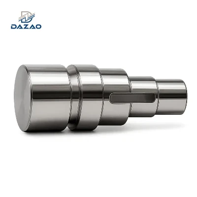
CNC turned and ground shafts to ±0.005mm tolerance.
Precision stepped shafts with concentricity ≤0.003mm.
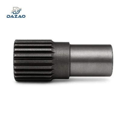
High torque spline shafts built from 4140 alloy steel.
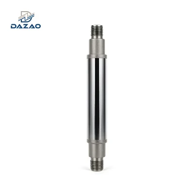
Submersible pump shafts featuring SS316L and hard chrome.
Automotive drive axle shafts with surface induction hardening.
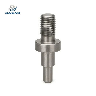
Custom threaded stud axles with ISO 6g precision threads.
Hollow drive shafts CNC machining with deep-hole drilling.
Reliable motor rotor shafts supplier with SPC batch control.
Xiamen Dazao Machinery is a specialized CNC turning and grinding facility operating for over 20 years. We support overseas industrial clients with components manufactured to design specifications. Our processes have matured through addressing field failures in motor rotor, submersible pump, and automotive drivetrain programs. This experience has allowed us to develop structured, repeatable controls for concentricity, thermal deformation compensation, and batch-to-batch statistical process control (SPC).
CNC Turned and Ground Shafts: Production Capabilities and Component Overview
Direct-from-source precision machining delivering dimensional accuracy up to ±0.005mm.
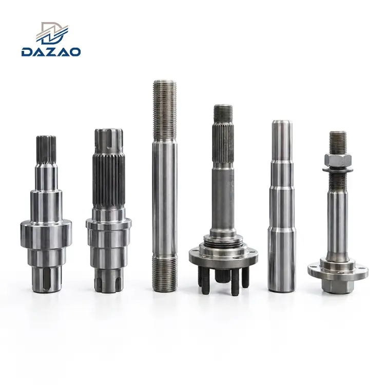
This series of custom CNC machined drive shafts and precision stepped shafts is processed via CNC lathe and centerless grinding operations. As a specialized motor rotor shafts supplier, we produce motor shafts, submersible pump shafts, automotive drive axle shafts, splined shafts, and custom threaded stud axles. Our facility works with carbon steel, alloy steel, stainless steel, and non-ferrous metals. We provide contract manufacturing for industrial electric motor builders, pump brands, automotive tier-1 suppliers, and automation equipment integrators.
Resolving Field Failures: Case Studies from Our 9-Year Shaft Machining History
Real-world engineering solutions that eliminate concentricity errors and component wear.
Instead of using generic quality claims, we provide transparent case studies of past manufacturing challenges and the engineering solutions we established to prevent them.
Concentricity Discrepancies in Precision Motor Rotor Shafts
During an early run of servo motor rotor shafts, we used sequential clamping where one step was machined, the part was flipped, and the opposite step was turned. The minor positioning errors between setups resulted in concentricity runouts up to 0.012mm across steps. The assembled motors experienced excessive vibration and noise, rendering them unusable.
We revised the process to utilize a single-clamping configuration with dual-dead centers. All outer diameters, shoulders, and snap-ring grooves are machined in a single setup, eliminating cumulative setup errors. We also integrated a 100% concentricity runout inspection step. Concentricity is now held under 0.003mm, resulting in a 60% reduction in motor vibration.
Hard Chrome Flaking and Dimensional Distortion in SS316L Submersible Pump Shafts
Early SS316L submersible pump shafts were turned, heat-treated, and direct-plated with hard chrome. Because we did not compensate for thermal distortion or prepare the stainless steel surface for plating, 20% of the shafts suffered chrome delamination and dimensional warpage after three months of field operations, causing seal failures and fluid leakage.
We established a dedicated pump shaft process flow. Post-heat treatment, parts undergo mechanical straightening and semi-precision grinding to correct warping before plating. We introduced a pre-plate abrasive blasting step to prepare the stainless steel surface, enhancing chromium adhesion. After plating, a final precision grinding and polishing pass is applied. This sequence has increased the chrome layer life in marine and chemical environments by up to three times.
Batch Consistency Drift in Splined Drive Shafts
During our first high-volume automotive splined shaft order, we verified only the first article before running the batch. Natural tool wear caused the spline pitch circle diameter to drift by 0.08mm from the start of the batch to the end. This drift created assembly fitment problems, with some splines too loose and others too tight.
We implemented a systematic Statistical Process Control (SPC) workflow. Operators inspect critical dimensions every 20 parts. We set mandatory tool-replacement thresholds based on wear limits and perform full CMM checks on the first part, the last part, and any parts run immediately after tool changes. This process maintains spline dimensions within ±0.01mm across runs.
Proprietary Processing Standards and In-House Quality Protocols
Standardized engineering controls replacing manual variations to guarantee structural stability.
Concentricity Control System for Precision Stepped Shafts
We do not rely on manual adjustments to maintain concentricity on multi-step shafts. Instead, we enforce a standardized sequence:
· Setup: One-clamping setups utilizing dual dead centers are used to prevent alignment errors. Slender shafts are supported by follow-rests to prevent tool-pressure deflection.
· Sequencing: Parts undergo rough turning, stress-relief thermal aging, semi-finish turning, and centerless fine grinding to prevent structural spring-back.
· Verification: Every shaft undergoes roundness and concentricity testing on specialized geometry testers, with inspection data archived and provided upon request.
Operational Condition-Matched Material and Heat Treatment Matrix
|
Component Requirement |
Base Material |
Thermal Treatment |
Performance Attributes |
Practical Limitations & Guidance |
|
Standard Motors / General Transmission |
AISI 1045 / S45C Carbon Steel |
Quench & Temper (Q&T) |
Balanced tensile strength and toughness for standard mechanical loads. |
Not suitable for high-wear or heavy shock-load systems. |
|
High-Torque / Heavy-Duty Shafts |
AISI 4140 / SCM440 Alloy Steel |
Quench & Temper (Q&T) |
High fatigue resistance and torsional strength for demanding applications. |
Low surface hardness; requires induction hardening if sliding wear occurs. |
|
Automotive Drives / High-Wear Pins |
AISI 8620 / 20CrNiMo Alloy Steel |
Case Carburizing & Quenching |
High surface wear resistance combined with a ductile core for impact absorption. |
Minor thermal distortion occurs; requires post-treatment grinding allowance. |
|
Corrosive Fluid Pump Shafts |
SS316L Stainless Steel |
Stress-Relief Annealing + Hard Chrome Plating |
High chemical and salt-water corrosion resistance with a wear-resistant exterior. |
Avoid high chloride concentrations; upgrade to duplex steel for extreme conditions. |
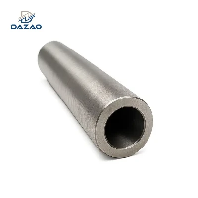
Long-Shaft Straightness & Stress-Relief Protocol
For shafts exceeding 500mm in length, thermal and mechanical stresses cause distortion. We manage this through a dedicated protocol:
1. Thermal Stress Relief: Applied after rough machining to release internal material stresses, preventing downstream movement.
2. Inverse-Deformation Machining: Tool paths during semi-finish turning are adjusted to compensate for expected thermal movement during subsequent heat treatment.
3. Mechanical Straightening: Parts undergo mechanical press-straightening and vibration aging prior to grinding.
4. Secondary Tempering: A low-temperature stress-relief step is performed after grinding to stabilize final dimensions. This protocol maintains straightness within 0.02mm/m for shafts up to 1500mm.
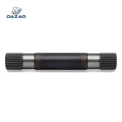
Technical Specifications and Precise Tolerance Matrix
Verified mechanical limits and dimensional metrics for critical engineering reviews.
|
Engineering Metric |
Manufacturing Capability Range |
Standard Production Tolerance |
|
Machining Diameter Range |
φ2.0 mm to φ300.0 mm |
±0.005 mm (g6, h6, h7 limits) |
|
Machining Length Range |
10.0 mm to 1500.0 mm |
±0.10 mm (shorter lengths to ±0.02 mm) |
|
Concentricity & Roundness |
Up to 1500.0 mm in length |
≤0.003 mm |
|
Straightness Limit |
Shafts up to 1500.0 mm |
≤0.02 mm/m |
|
Surface Roughness (Turned) |
CNC lathe finishing |
Ra 0.8 μm to Ra 1.6 μm |
|
Surface Roughness (Ground) |
Centerless grinding |
Ra 0.1 μm to Ra 0.4 μm |
|
Key Machining Processes |
CNC turning, centerless grinding, spline milling, thread rolling, deep-hole drilling |
Configured per part geometry |
|
Material Standards |
Carbon Steel, Alloy Steel, Stainless Steel, Brass, Copper, Aluminum, Titanium |
ASTM, DIN, JIS, GB |
|
Thermal Treatments |
Quench & Temper, Induction Hardening, Carburizing, Nitriding |
Hardness depth verified by testing |
|
Plating & Surface Finishes |
Zinc, Nickel, Hard Chrome Plating, Black Oxide, Anodizing, Passivation |
Thickness verified by eddy-current testing |
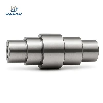
Target Application Fields and Operational Environments
Proven performance in heavy-duty drivetrains, fluid dynamics, and high-speed rotary systems.
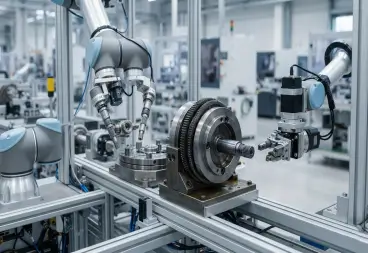
Industrial Automation Systems
Used in end-of-arm tooling, collaborative robot joints, rotary actuators, and indexers requiring high dimensional consistency.

Fluid Handling & Pump Systems
Applied in submersible pumps, chemical process equipment, and wastewater handling where corrosion resistance and shaft runout are closely managed.
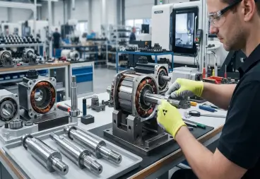
Electric Drivetrains & Motor Manufacturing
Fitted in high-speed servo motors, stepper motors, and industrial motor rotors to minimize high-RPM vibration.
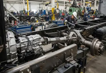
Automotive & Commercial Vehicles
Used for drive axles, half-shafts, power transmission linkages, and gearbox inputs designed for fatigue resistance.
FAQs
01.Can you manufacture precision electric motor shafts with low vibration?
02.What materials do you use for high torque spline shafts?
03.How do you prevent corrosion and wear on submersible pump shafts?
04.Do you machine heavy-duty automotive drive axle shafts?
05.What tolerances can your CNC turned and ground shafts achieve?
06.Can you produce custom threaded stud axles for automation machinery?
Submit Engineering Drawings for Rapid DFM Evaluation
Accelerate your development cycle with verified manufacturing feedback within 24 hours.
Submit Your Engineering Drawings for Design for Manufacturability (DFM) Review
For custom shafts, step pins, or threaded axles, submit your 2D drawings (PDF/DWG with tolerances specified) and 3D CAD files (STEP/IGS format).
Our engineering team will review your geometries, evaluate tool clearances, and provide a detailed DFM feedback report alongside a formal quote within 24 hours.
Contact Us

Hot Tags: cnc machined drive shafts,precision stepped shafts,submersible pump shafts,motor rotor shafts, Aluminum CNC Turning Parts, Brass CNC Turning Parts, cnc machining service, cnc turning parts, CNC Turning Plastic Parts, Stainless Steel Turning Parts